lock FIAT FIORINO 2010 Owner handbook (in English)
[x] Cancel search | Manufacturer: FIAT, Model Year: 2010, Model line: FIORINO, Model: FIAT FIORINO 2010Pages: 210, PDF Size: 4.9 MB
Page 128 of 210
127
SAFETY
MAINTENANCE
AND CARE
TECHNICAL
SPECIFICATIONS
INDEX
DASHBOARDAND CONTROLS
STARTING
AND DRIVING
WARNING
LIGHTS AND
MESSAGES
IN AN
EMERGENCY
fig. 4F0T0120m
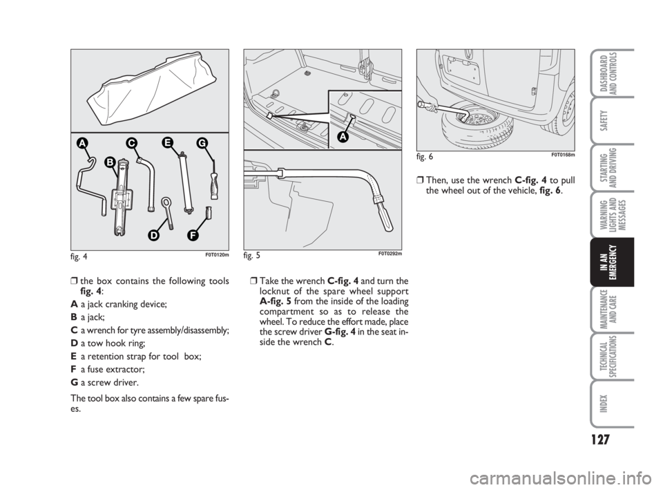
❒Take the wrench C-fig. 4and turn the
locknut of the spare wheel support
A-fig. 5from the inside of the loading
compartment so as to release the
wheel. To reduce the effort made, place
the screw driver G-fig. 4in the seat in-
side the wrench C.❒Then, use the wrench C-fig. 4to pull
the wheel out of the vehicle, fig. 6.
❒the box contains the following tools
fig. 4:
Aa jack cranking device;
Ba jack;
Ca wrench for tyre assembly/disassembly;
Da tow hook ring;
Ea retention strap for tool box;
Fa fuse extractor;
Ga screw driver.
The tool box also contains a few spare fus-
es.
fig. 6F0T0168m
fig. 5
A
F0T0292m
123-154 Fiorino GB 1ed:123-154 Fiorino GB 1ed 3-12-2009 15:33 Pagina 127
Page 130 of 210
129
SAFETY
MAINTENANCE
AND CARE
TECHNICAL
SPECIFICATIONS
INDEX
DASHBOARDAND CONTROLS
STARTING
AND DRIVING
WARNING
LIGHTS AND
MESSAGES
IN AN
EMERGENCY
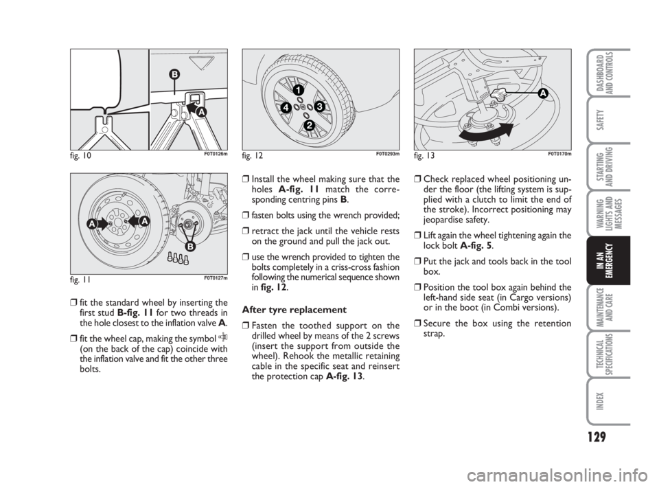
❒fit the standard wheel by inserting the
first stud B-fig. 11for two threads in
the hole closest to the inflation valve A.
❒fit the wheel cap, making the symbol
C(on the back of the cap) coincide with
the inflation valve and fit the other three
bolts.❒Install the wheel making sure that the
holes A-fig. 11match the corre-
sponding centring pins B.
❒fasten bolts using the wrench provided;
❒retract the jack until the vehicle rests
on the ground and pull the jack out.
❒use the wrench provided to tighten the
bolts completely in a criss-cross fashion
following the numerical sequence shown
in fig. 12.
After tyre replacement
❒Fasten the toothed support on the
drilled wheel by means of the 2 screws
(insert the support from outside the
wheel). Rehook the metallic retaining
cable in the specific seat and reinsert
the protection cap A-fig. 13.❒Check replaced wheel positioning un-
der the floor (the lifting system is sup-
plied with a clutch to limit the end of
the stroke). Incorrect positioning may
jeopardise safety.
❒Lift again the wheel tightening again the
lock boltA-fig. 5.
❒Put the jack and tools back in the tool
box.
❒Position the tool box again behind the
left-hand side seat (in Cargo versions)
or in the boot (in Combi versions).
❒Secure the box using the retention
strap.
fig. 10F0T0126m
fig. 11F0T0127m
fig. 12
4
1
3
2
F0T0293mfig. 13F0T0170m
123-154 Fiorino GB 1ed:123-154 Fiorino GB 1ed 3-12-2009 15:33 Pagina 129
Page 134 of 210
133
SAFETY
MAINTENANCE
AND CARE
TECHNICAL
SPECIFICATIONS
INDEX
DASHBOARDAND CONTROLS
STARTING
AND DRIVING
WARNING
LIGHTS AND
MESSAGES
IN AN
EMERGENCY
❒If at least 1.8 bar pressure is read, re-
store proper pressure (with engine
running and handbrake on) and restart.
❒Drive with the utmost care to the near-
est Fiat Dealership.FOR CHECKING AND
RESTORING PRESSURE ONLY
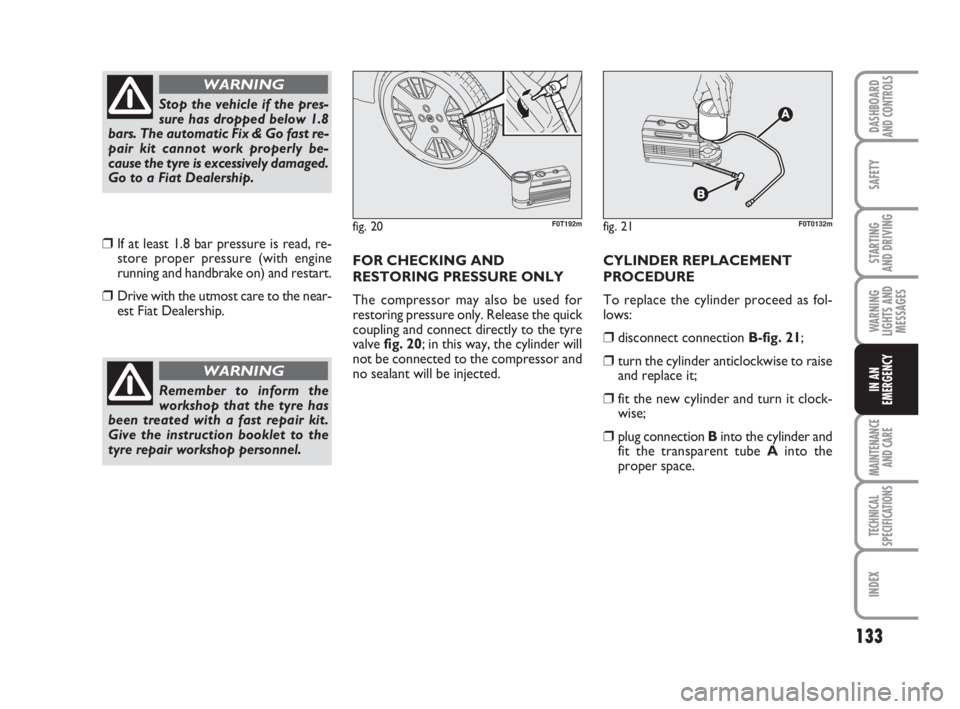
The compressor may also be used for
restoring pressure only. Release the quick
coupling and connect directly to the tyre
valve fig. 20; in this way, the cylinder will
not be connected to the compressor and
no sealant will be injected. CYLINDER REPLACEMENT
PROCEDURE
To replace the cylinder proceed as fol-
lows:
❒disconnect connection B-fig. 21;
❒turn the cylinder anticlockwise to raise
and replace it;
❒fit the new cylinder and turn it clock-
wise;
❒plug connection Binto the cylinder and
fit the transparent tube Ainto the
proper space.
Stop the vehicle if the pres-
sure has dropped below 1.8
bars. The automatic Fix & Go fast re-
pair kit cannot work properly be-
cause the tyre is excessively damaged.
Go to a Fiat Dealership.
WARNING
Remember to inform the
workshop that the tyre has
been treated with a fast repair kit.
Give the instruction booklet to the
tyre repair workshop personnel.
WARNING
fig. 20F0T192mfig. 21F0T0132m
123-154 Fiorino GB 1ed:123-154 Fiorino GB 1ed 3-12-2009 15:33 Pagina 133
Page 136 of 210
135
SAFETY
MAINTENANCE
AND CARE
TECHNICAL
SPECIFICATIONS
INDEX
DASHBOARDAND CONTROLS
STARTING
AND DRIVING
WARNING
LIGHTS AND
MESSAGES
IN AN
EMERGENCY
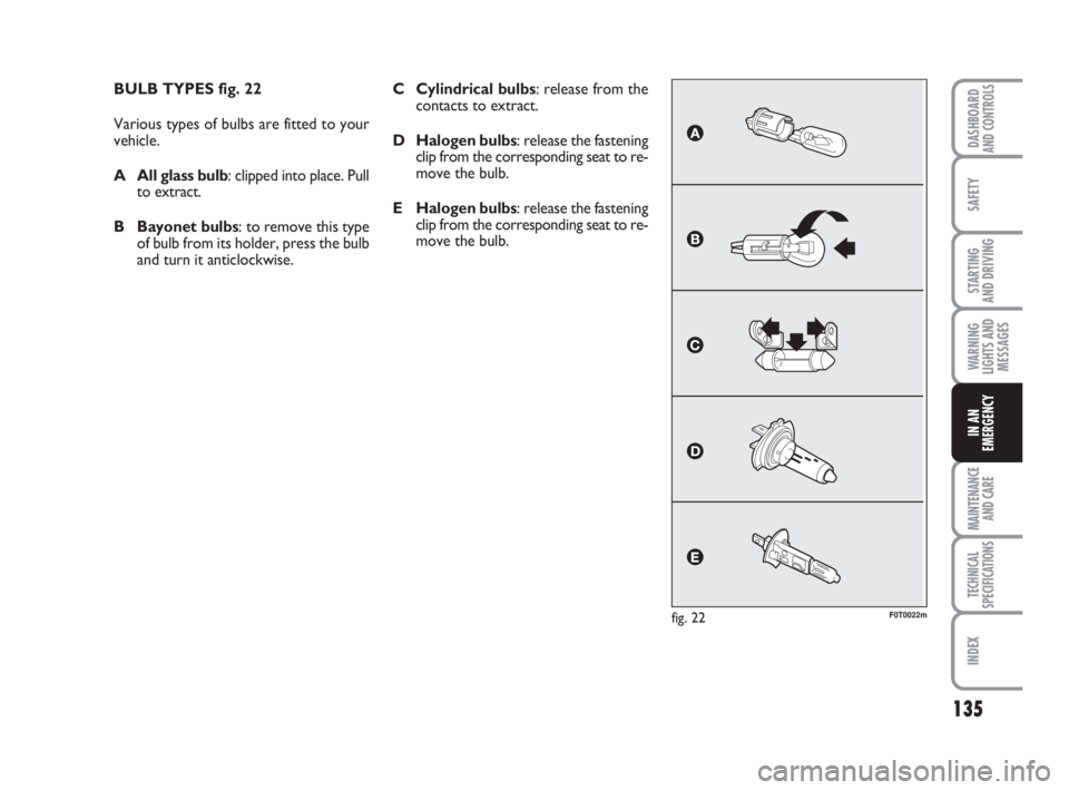
BULB TYPES fig. 22
Various types of bulbs are fitted to your
vehicle.
A All glass bulb: clipped into place. Pull
to extract.
B Bayonet bulbs: to remove this type
of bulb from its holder, press the bulb
and turn it anticlockwise.
fig. 22F0T0022m
C Cylindrical bulbs: release from the
contacts to extract.
D Halogen bulbs: release the fastening
clip from the corresponding seat to re-
move the bulb.
E Halogen bulbs: release the fastening
clip from the corresponding seat to re-
move the bulb.
123-154 Fiorino GB 1ed:123-154 Fiorino GB 1ed 3-12-2009 15:33 Pagina 135
Page 138 of 210
137
SAFETY
MAINTENANCE
AND CARE
TECHNICAL
SPECIFICATIONS
INDEX
DASHBOARDAND CONTROLS
STARTING
AND DRIVING
WARNING
LIGHTS AND
MESSAGES
IN AN
EMERGENCY
IF AN EXTERIOR
LIGHT BURNS OUT
For the type of bulb and power rating, see
“When needing to change a bulb”.
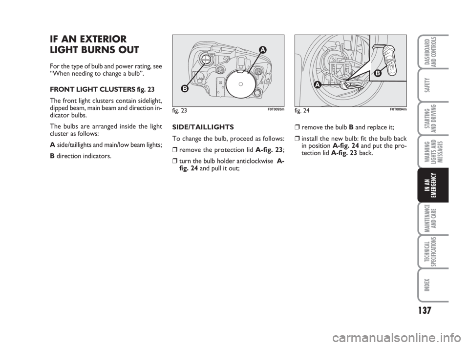
FRONT LIGHT CLUSTERS fig. 23
The front light clusters contain sidelight,
dipped beam, main beam and direction in-
dicator bulbs.
The bulbs are arranged inside the light
cluster as follows:
Aside/taillights and main/low beam lights;
Bdirection indicators.SIDE/TAILLIGHTS
To change the bulb, proceed as follows:
❒remove the protection lid A-fig. 23;
❒turn the bulb holder anticlockwise A-
fig. 24and pull it out;❒remove the bulb Band replace it;
❒install the new bulb: fit the bulb back
in position A-fig. 24and put the pro-
tection lid A-fig. 23back.
fig. 23F0T0093mfig. 24F0T0094m
123-154 Fiorino GB 1ed:123-154 Fiorino GB 1ed 3-12-2009 15:33 Pagina 137
Page 139 of 210
138
SAFETY
MAINTENANCE
AND CARE
TECHNICAL
SPECIFICATIONS
INDEX
DASHBOARDAND CONTROLS
STARTING
AND DRIVING
WARNING
LIGHTS AND
MESSAGES
IN AN
EMERGENCY
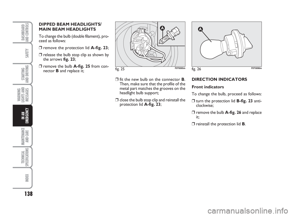
DIPPED BEAM HEADLIGHTS/
MAIN BEAM HEADLIGHTS
To change the bulb (double filament), pro-
ceed as follows:
❒remove the protection lid A-fig. 23;
❒release the bulb stop clip as shown by
the arrows fig. 23;
❒remove the bulb A-fig. 25from con-
nector Band replace it;
❒fit the new bulb on the connector B.
Then, make sure that the profile of the
metal part matches the grooves on the
headlight bulb support;
❒close the bulb stop clip and reinstall the
protection lid A-fig. 23;DIRECTION INDICATORS
Front indicators
To change the bulb, proceed as follows:
❒turn the protection lid B-fig. 23anti-
clockwise;
❒remove the bulb A-fig. 26and replace
it;
❒reinstall the protection lid B.
fig. 25F0T0095mfig. 26F0T0096m
123-154 Fiorino GB 1ed:123-154 Fiorino GB 1ed 3-12-2009 15:33 Pagina 138
Page 140 of 210
139
SAFETY
MAINTENANCE
AND CARE
TECHNICAL
SPECIFICATIONS
INDEX
DASHBOARDAND CONTROLS
STARTING
AND DRIVING
WARNING
LIGHTS AND
MESSAGES
IN AN
EMERGENCY
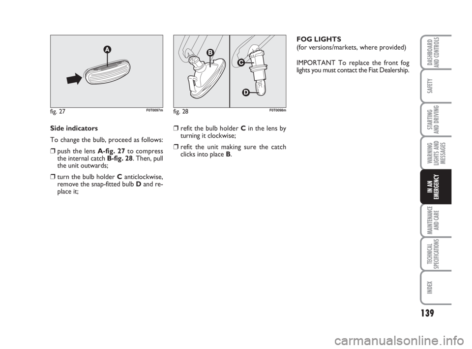
Side indicators
To change the bulb, proceed as follows:
❒push the lens A-fig. 27to compress
the internal catch B-fig. 28. Then, pull
the unit outwards;
❒turn the bulb holder C anticlockwise,
remove the snap-fitted bulb Dand re-
place it;
fig. 27F0T0097mfig. 28F0T0098m
❒refit the bulb holder Cin the lens by
turning it clockwise;
❒refit the unit making sure the catch
clicks into place B.FOG LIGHTS
(for versions/markets, where provided)
IMPORTANT To replace the front fog
lights you must contact the Fiat Dealership.
123-154 Fiorino GB 1ed:123-154 Fiorino GB 1ed 3-12-2009 15:33 Pagina 139
Page 142 of 210

141
SAFETY
MAINTENANCE
AND CARE
TECHNICAL
SPECIFICATIONS
INDEX
DASHBOARDAND CONTROLS
STARTING
AND DRIVING
WARNING
LIGHTS AND
MESSAGES
IN AN
EMERGENCY
3rdSTOP LIGHTS fig. 33
To replace the 3
rdstop lights you must
contact the Fiat Dealership.
fig. 33F0T0103mfig. 34F0T0104mfig. 35F0T0105m
PLATE LIGHTS
To replace the bulbs A-fig. 34proceed as
follows:
❒pull the tongues indicated by the arrows
and remove the bulb holders;
❒turn the bulb holder B-fig. 35clock-
wise and take the bulb Cout.
123-154 Fiorino GB 1ed:123-154 Fiorino GB 1ed 3-12-2009 15:33 Pagina 141
Page 143 of 210
142
SAFETY
MAINTENANCE
AND CARE
TECHNICAL
SPECIFICATIONS
INDEX
DASHBOARDAND CONTROLS
STARTING
AND DRIVING
WARNING
LIGHTS AND
MESSAGES
IN AN
EMERGENCY
IF THE INTERIOR
LIGHT BURNS OUT
For the type of bulb and power rating, see
“When needing to change a bulb”.
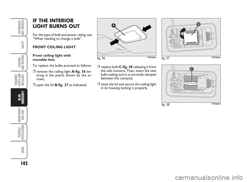
FRONT CEILING LIGHT
Front ceiling light with
movable lens
To replace the bulbs proceed as follows:
❒remove the ceiling light A-fig. 36lev-
ering in the points shown by the ar-
rows;
❒open the lid B-fig. 37as indicated;❒replace bulb C-fig. 38releasing it from
the side contacts. Then, insert the new
bulb making sure it is correctly clamped
between the contacts;
❒close the lid and secure the ceiling light
in its housing locking it properly.
fig. 36F0T0106mfig. 37F0T0023m
fig. 38F0T0024m
123-154 Fiorino GB 1ed:123-154 Fiorino GB 1ed 3-12-2009 15:33 Pagina 142
Page 144 of 210
143
SAFETY
MAINTENANCE
AND CARE
TECHNICAL
SPECIFICATIONS
INDEX
DASHBOARDAND CONTROLS
STARTING
AND DRIVING
WARNING
LIGHTS AND
MESSAGES
IN AN
EMERGENCY
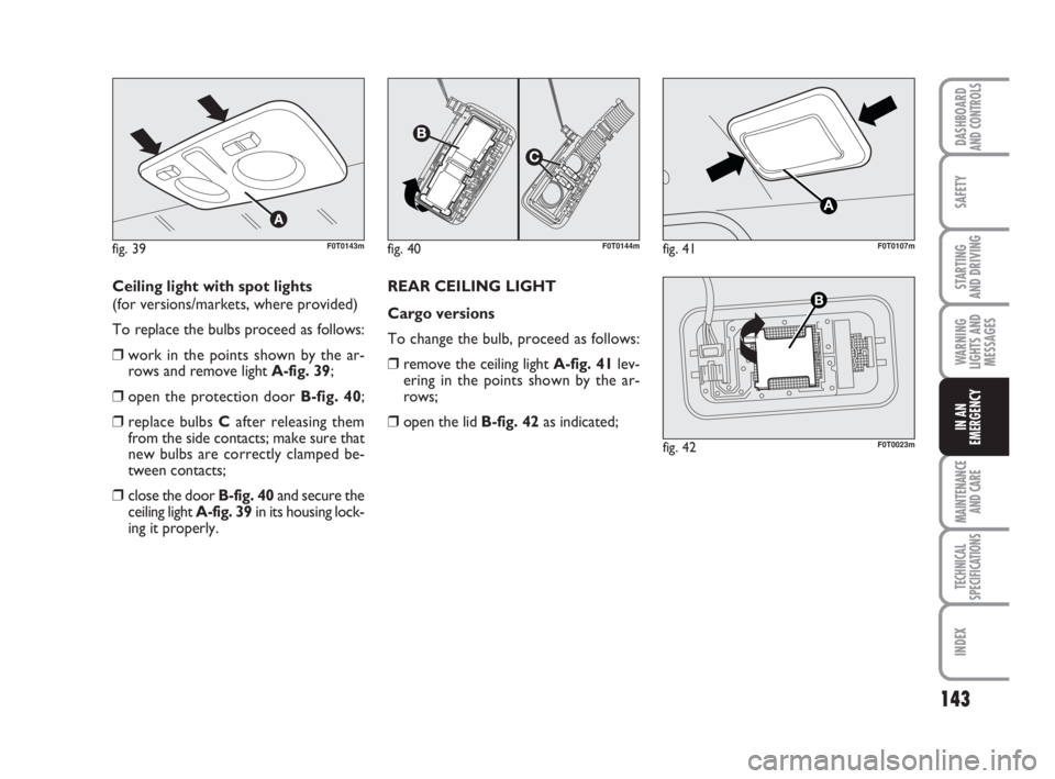
Ceiling light with spot lights
(for versions/markets, where provided)
To replace the bulbs proceed as follows:
❒work in the points shown by the ar-
rows and remove light A-fig. 39;
❒open the protection door B-fig. 40;
❒replace bulbs Cafter releasing them
from the side contacts; make sure that
new bulbs are correctly clamped be-
tween contacts;
❒close the door B-fig. 40and secure the
ceiling light A-fig. 39in its housing lock-
ing it properly.REAR CEILING LIGHT
Cargo versions
To change the bulb, proceed as follows:
❒remove the ceiling light A-fig. 41lev-
ering in the points shown by the ar-
rows;
❒open the lid B-fig. 42as indicated;
fig. 39F0T0143mfig. 40F0T0144mfig. 41F0T0107m
fig. 42F0T0023m
123-154 Fiorino GB 1ed:123-154 Fiorino GB 1ed 3-12-2009 15:33 Pagina 143