key FIAT FIORINO 2017 Owner handbook (in English)
[x] Cancel search | Manufacturer: FIAT, Model Year: 2017, Model line: FIORINO, Model: FIAT FIORINO 2017Pages: 272, PDF Size: 5.87 MB
Page 67 of 272
WARNING
Never travel with the glove
compartment open: it could injure the
passenger in the event of a crash.FRONT POWER SOCKET (12V)
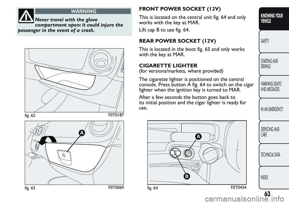
This is located on the central unit fig. 64 and only
works with the key at MAR.
Lift cap B to use fig. 64.
REAR POWER SOCKET (12V)
This is located in the boot fig. 65 and only works
with the key at MAR.
CIGARETTE LIGHTER
(for versions/markets, where provided)
The cigarette lighter is positioned on the central
console. Press button A fig. 64 to switch on the cigar
lighter when the ignition key is turned to MAR.
After a few seconds the button goes back to
its initial position and the cigar lighter is ready for
use.
fig. 62F0T0187
fig. 63F0T0069fig. 64F0T0454
63
KNOWING YOUR
VEHICLE
SAFETY
STARTING AND
DRIVING
WARNING LIGHTS
AND MESSAGES
IN AN EMERGENCY
SERVICING AND
CARE
TECHNICAL DATA
INDEX
Page 71 of 272
DOORS
DOOR CENTRAL LOCKING/UNLOCKING
Locking from the outside
The doors will be locked only if all doors are shut. If
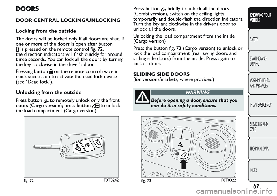
one or more of the doors is open after button
is pressed on the remote control fig. 72,
the direction indicators will flash quickly for around
three seconds. You can lock all the doors by turning
the key clockwise in the driver's door.
Pressing button
on the remote control twice in
quick succession to activate the dead lock device
(see "Dead lock").
Unlocking from the outside
Press button
to remotely unlock only the front
doors (Cargo version); press button
to unlock
the load compartment (Cargo version).Press button
briefly to unlock all the doors
(Combi version), switch on the ceiling lights
temporarily and double-flash the direction indicators.
Turn the key anticlockwise in the driver's door to
unlock all the doors.
Unlocking the load compartment from the inside
(Cargo version)
Press the button fig. 73 (Cargo version) to unlock or
lock the load compartment (rear swing doors and
sliding side doors) from the inside. Press again to
lock all doors.
SLIDING SIDE DOORS
(for versions/markets, where provided)
WARNING
Before opening a door, ensure that you
can do it in safety conditions.
fig. 72F0T0242fig. 73F0T0322
67
KNOWING YOUR
VEHICLE
SAFETY
STARTING AND
DRIVING
WARNING LIGHTS
AND MESSAGES
IN AN EMERGENCY
SERVICING AND
CARE
TECHNICAL DATA
INDEX
Page 72 of 272
Make sure that the right sliding side door
is all closed before refuelling to prevent
damage to the door and to the sliding
locking system with fuel filler cap open, activated
during refuelling operations.
WARNING
The right sliding side door cannot be
opened with the fuel flap open during
refuelling.
On Cargo versions, the sliding side door is fitted
with a spring-loaded latch that stops the door from
opening any further. To lock it, simply push the
door as far as it will go; to unlock it, pull forward
firmly.
In any case, make sure that the door is properly
hooked to the system which keeps the door fully
open.
WARNING
Do not leave the sliding side door open
when the vehicle is parked on a
gradient . A knock could release the latch leaving
the door free to move.
WARNING
Before leaving the vehicle parked with
sliding doors open, always check that
the latch is engaged.
Opening/closing from the outside
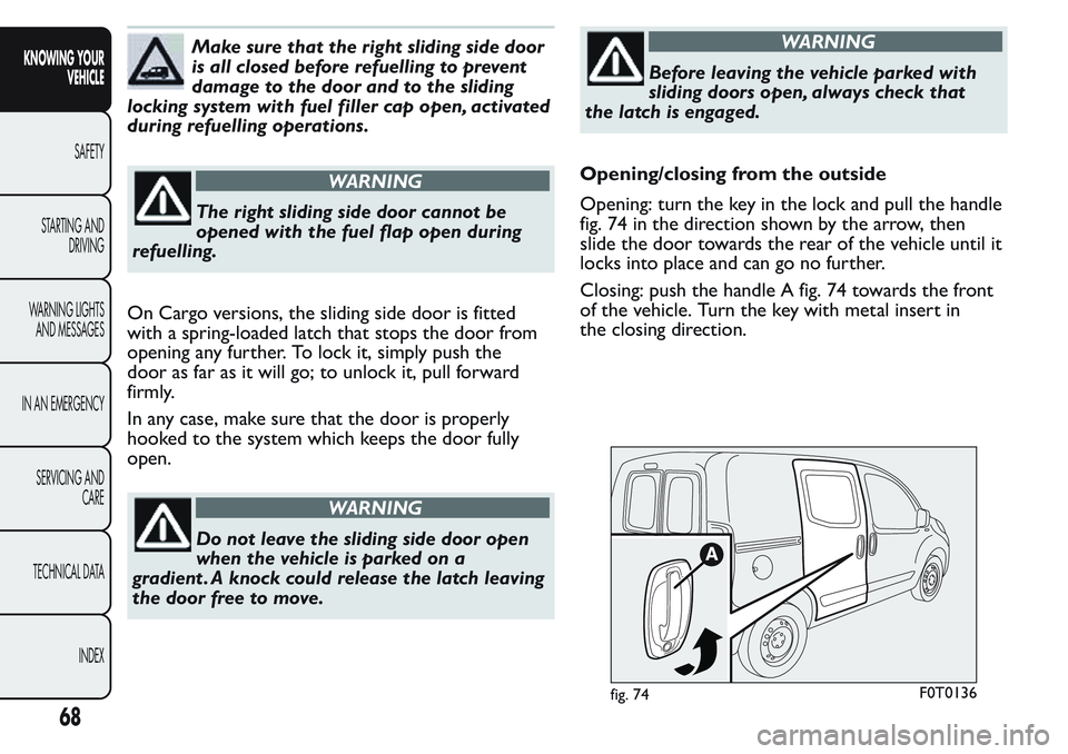
Opening: turn the key in the lock and pull the handle
fig. 74 in the direction shown by the arrow, then
slide the door towards the rear of the vehicle until it
locks into place and can go no further.
Closing: push the handle A fig. 74 towards the front
of the vehicle. Turn the key with metal insert in
the closing direction.
fig. 74F0T0136
68
KNOWING YOUR
VEHICLE
SAFETY
STARTING AND
DRIVING
WARNING LIGHTS
AND MESSAGES
IN AN EMERGENCY
SERVICING AND
CARE
TECHNICAL DATA
INDEX
Page 74 of 272
The device remains engaged even if the doors are
unlocked remotely.
WARNING
Always use this device when carr ying
children.
DOUBLE REAR SWING DOORS
(for versions/markets, where provided)
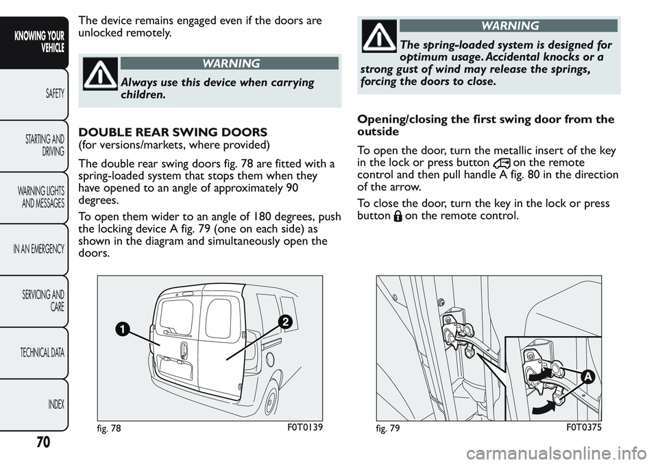
The double rear swing doors fig. 78 are fitted with a
spring-loaded system that stops them when they
have opened to an angle of approximately 90
degrees.
To open them wider to an angle of 180 degrees, push
the locking device A fig. 79 (one on each side) as
shown in the diagram and simultaneously open the
doors.
WARNING
The spring-loaded system is designed for
optimum usage. Accidental knocks or a
strong gust of wind may release the springs,
forcing the doors to close.
Opening/closing the first swing door from the
outside
To open the door, turn the metallic insert of the key
in the lock or press button
on the remote
control and then pull handle A fig. 80 in the direction
of the arrow.
To close the door, turn the key in the lock or press
button
on the remote control.
fig. 78F0T0139fig. 79F0T0375
70
KNOWING YOUR
VEHICLE
SAFETY
STARTING AND
DRIVING
WARNING LIGHTS
AND MESSAGES
IN AN EMERGENCY
SERVICING AND
CARE
TECHNICAL DATA
INDEX
Page 76 of 272
WINDOWS
FRONT ELECTRIC WINDOWS
(for versions/markets, where provided)
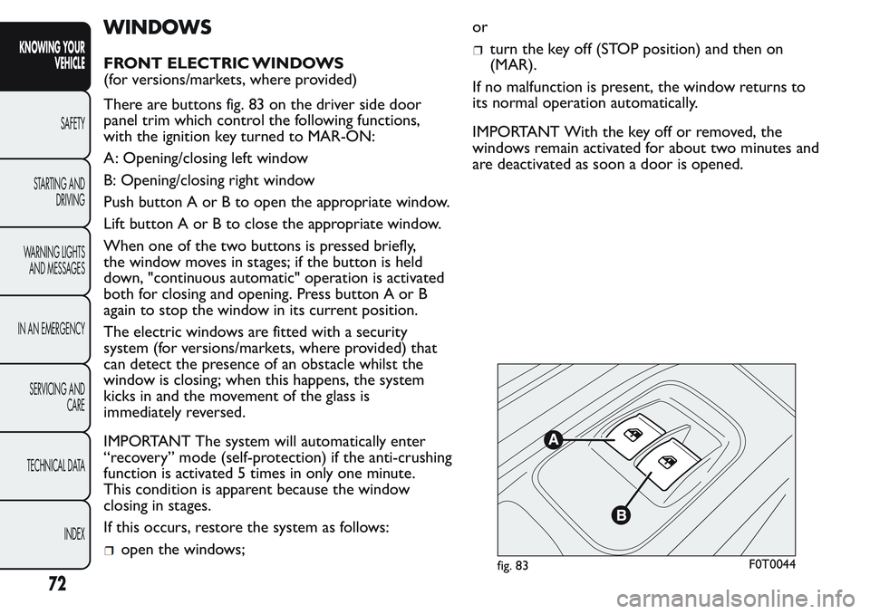
There are buttons fig. 83 on the driver side door
panel trim which control the following functions,
with the ignition key turned to MAR-ON:
A: Opening/closing left window
B: Opening/closing right window
Push button A or B to open the appropriate window.
Lift button A or B to close the appropriate window.
When one of the two buttons is pressed briefly,
the window moves in stages; if the button is held
down, "continuous automatic" operation is activated
both for closing and opening. Press button A or B
again to stop the window in its current position.
The electric windows are fitted with a security
system (for versions/markets, where provided) that
can detect the presence of an obstacle whilst the
window is closing; when this happens, the system
kicks in and the movement of the glass is
immediately reversed.
IMPORTANT The system will automatically enter
“recovery” mode (self-protection) if the anti-crushing
function is activated 5 times in only one minute.
This condition is apparent because the window
closing in stages.
If this occurs, restore the system as follows:
open the windows;or
turn the key off (STOP position) and then on
(MAR).
If no malfunction is present, the window returns to
its normal operation automatically.
IMPORTANT With the key off or removed, the
windows remain activated for about two minutes and
are deactivated as soon a door is opened.
fig. 83F0T0044
72
KNOWING YOUR
VEHICLE
SAFETY
STARTING AND
DRIVING
WARNING LIGHTS
AND MESSAGES
IN AN EMERGENCY
SERVICING AND
CARE
TECHNICAL DATA
INDEX
Page 77 of 272
WARNING
Improper use of the electric windows
can be dangerous. Before and during
their operation ensure that passengers are not
at risk from the moving glass, either by personal
objects caught in the mechanism or struck by
it directly. When leaving the car, always remove
the ignition key to avoid the risk of injury due
to accidental operation of the electric
windows.
MANUAL FRONT WINDOWS
On some versions, the front windows are opened
and closed manually.
Wind the handle to open/close.
LUGGAGE COMPARTMENT
EMERGENCY OPENING FROM THE INSIDE
In the event of an emergency, you can open the
tailgate from inside as follows:
open the sliding side door and lower the backrest
of the rear seat to gain access to the boot (Combi
versions);
or
open the sliding side door (Cargo versions);
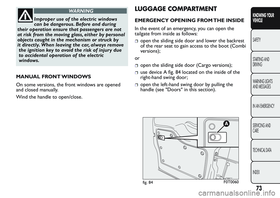
use device A fig. 84 located on the inside of the
right-hand swing door;
open the left-hand swing door by pulling the
handle (see "Doors" in this section).
fig. 84F0T0060
73
KNOWING YOUR
VEHICLE
SAFETY
STARTING AND
DRIVING
WARNING LIGHTS
AND MESSAGES
IN AN EMERGENCY
SERVICING AND
CARE
TECHNICAL DATA
INDEX
Page 84 of 272
HEADLIGHTS
LIGHT BEAM DIRECTION
The correct direction of the headlights is essential
for the comfort and safety of the driver and other
road users. To ensure the best visibility when
travelling with the headlights on, the headlight
alignment must be correct. Contact a Fiat Dealership
to have the direction checked and, if necessary,
adjusted.
HEADLIGHT ALIGNMENT CORRECTOR
This device works with the ignition key in the MAR
position and the dipped headlights on.
The vehicle tilts backwards when it is laden, raising
the beam.
The beams must therefore be aimed again in this
case.Adjusting headlight alignment
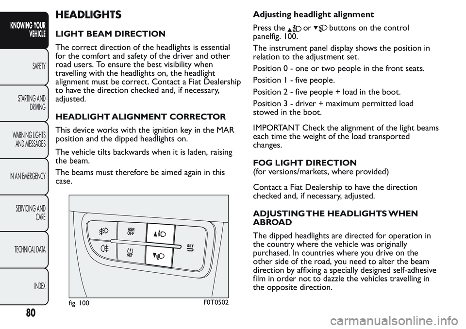
Press theorbuttons on the control
panelfig. 100.
The instrument panel display shows the position in
relation to the adjustment set.
Position 0 - one or two people in the front seats.
Position1-fivepeople.
Position2-fivepeople + load in the boot.
Position 3 - driver + maximum permitted load
stowed in the boot.
IMPORTANT Check the alignment of the light beams
each time the weight of the load transported
changes.
FOG LIGHT DIRECTION
(for versions/markets, where provided)
Contact a Fiat Dealership to have the direction
checked and, if necessary, adjusted.
ADJUSTING THE HEADLIGHTS WHEN
ABROAD
The dipped headlights are directed for operation in
the country where the vehicle was originally
purchased. In countries where you drive on the
other side of the road, you need to alter the beam
direction by affixing a specially designed self-adhesive
film in order not to dazzle the vehicles travelling in
the opposite direction.
fig. 100F0T0502
80
KNOWING YOUR
VEHICLE
SAFETY
STARTING AND
DRIVING
WARNING LIGHTS
AND MESSAGES
IN AN EMERGENCY
SERVICING AND
CARE
TECHNICAL DATA
INDEX
Page 93 of 272
WARNING
If the driver depresses the brake pedal
fully or carries out a fast steering during
system operation, the automatic braking
function may stop (e.g. to allow a possible
manoeuvre to avoid the obstacle).
WARNING
The laser beam is not visible at the
naked eye. Do not look directly, or with
optical instruments (e.g. lenses), at the laser
beam from a distance lower than 10 cm: this
may cause damage to the sight .The laser beam
is also present when the key is at MAR but its
operation is off, not available or manually
deactivated with the display Setup Menu.
WARNING
The system intervenes on vehicles
travelling in the same lane. Small sized
vehicles (e.g. bicycles or motorbikes) or people,
animals and things (e.g. pushchairs) and more in
general all those obstacles with a low reflection
of the light emitted by the laser (e.g. vehicles
soiled with mud) are not taken into
consideration.
WARNING
If the car must be placed on a roller
bench (at a speed within 5 and 30 km/h)
for maintenance interventions or if it is washed
in an automatic roller washing tunnel with an
obstacle in the front part (e.g. another car, a
wall or another obstacle), the system may
detect its presence and activate. In this case the
system must be deactivated through the
display Setup Menu.
The laser sensor may have limited or
absent operation due to weather
conditions such as: heavy rain, hail, thick
fog, heavy snow, formation of ice layers on the
windscreen.
Sensor operation may also be
compromised by the presence of dust ,
condensation, dirt or ice on the
windscreen, by traffic conditions (e.g. vehicles
that are driving not aligned with your car, vehicle
driving in a transverse or opposite way on the
same lane, bend with a small radius of curvature),
by road surface conditions and by driving
conditions (e.g. off-road driving). Make sure the
windscreen is always clean. Use specific
detergents and clean cloths to avoid scratching
the windscreen.The sensor operation may also be
limited or absent in some driving, traffic and
road surface conditions.
89
KNOWING YOUR
VEHICLE
SAFETY
STARTING AND
DRIVING
WARNING LIGHTS
AND MESSAGES
IN AN EMERGENCY
SERVICING AND
CARE
TECHNICAL DATA
INDEX
Page 96 of 272
EOBD SYSTEM
The EOBD system (European On Board Diagnosis)
allows continuous diagnosis of emission-related
components on the vehicle.
It also alerts the driver, by turning on instrument
panel warning light
(together with the relevant
message in the display, on some versions), when
these components are no longer in peak condition
(see “Warning lights and messages” section).
The aim of the system is to:
monitor system efficiency;
warn about increased emissions due to a vehicle
malfunction;
to warn of the need to replace deteriorated
components.
The system also has a connector that can be
interfaced with appropriate equipment, which makes
it possible to read the error codes stored in the
control unit, together with a series of specific
parameters for engine operation and diagnosis.
This check can also be carried out by traffic police.
IMPORTANT After resolving the problem, to check
the system completely, Fiat Dealerships are obliged
to run a bench test and, if necessary, road tests
which may call for a long journey.
WARNING
Go to a Fiat Dealership as soon as
possible if warning light
either does
not light up when the key is turned to MAR to if
while travelling the warning lights comes on
either steady or blinking (along with a message
on the display).The operation of warning light
may be checked by the traffic police using
specific devices. Follow the laws in force in
the country where you are driving.
92
KNOWING YOUR
VEHICLE
SAFETY
STARTING AND
DRIVING
WARNING LIGHTS
AND MESSAGES
IN AN EMERGENCY
SERVICING AND
CARE
TECHNICAL DATA
INDEX
Page 101 of 272
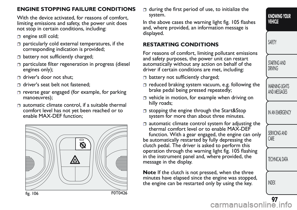
ENGINE STOPPING FAILURE CONDITIONS
With the device activated, for reasons of comfort,
limiting emissions and safety, the power unit does
not stop in certain conditions, including:
engine still cold;
particularly cold external temperatures, if the
corresponding indication is provided;
battery not sufficiently charged;
particulate filter regeneration in progress (diesel
engines only);
driver's door not shut;
driver's seat belt not fastened;
reverse gear engaged (for example, for parking
manoeuvres);
automatic climate control, if a suitable thermal
comfort level has not yet been reached or to
enable MAX-DEF function;
during the first period of use, to initialize the
system.
In the above cases the warning light fig. 105 flashes
and, where provided, an information message is
displayed.
RESTARTING CONDITIONS
For reasons of comfort, limiting pollutant emissions
and safety purposes, the power unit can restart
automatically without any action on behalf of the
driver if certain conditions are met, including:
battery not sufficiently charged;
reduced braking system vacuum, e.g. following the
brake pedal being pressed repeatedly;
vehicle in motion, for example when driving on
hilly roads;
stopping the engine through the Start&Stop
system for more than about three minutes.
automatic climate control system for adjusting the
thermal comfort level or to enable MAX-DEF
function. With a gear engaged, the engine can only
be automatically restarted by fully depressing the
clutch pedal. The driver is asked to perform this
operation through the warning light fig. 105 flashing
in the instrument panel and, where provided, the
message in the display.
NoteIf the clutch is not pressed, when the three
minutes have elapsed since the engine was stopped,
the engine can be restarted only by using the key.
fig. 106F0T0426
97
KNOWING YOUR
VEHICLE
SAFETY
STARTING AND
DRIVING
WARNING LIGHTS
AND MESSAGES
IN AN EMERGENCY
SERVICING AND
CARE
TECHNICAL DATA
INDEX