ESP FIAT FIORINO 2018 Owner handbook (in English)
[x] Cancel search | Manufacturer: FIAT, Model Year: 2018, Model line: FIORINO, Model: FIAT FIORINO 2018Pages: 196, PDF Size: 4.99 MB
Page 4 of 196
READ THIS CAREFULLY
REFUELLINGPetrol engines: only refuel with unleaded petrol with an octane rating (RON) of no less than 95 conforming to the European specification EN
228.
Diesel engines: only use diesel fuel for motor vehicles conforming to the European specification EN 590. The use of other products or
mixtures may damage the engine beyond repair and consequently invalidate the warranty, due to the damage caused.
Refuelling with methane: refuel only with methane for motor vehicles. The use of other products or mixtures may damage the engine
beyond repair and consequently invalidate the warranty, due to the damage caused.
For further details on the use of the correct fuel see the "Refuelling the vehicle" paragraph in the "Starting and driving" chapter.
STARTING THE ENGINE
Versions with manual transmission (petrol engines): make sure that the handbrake is engaged; put the gear lever in neutral; fully
depress the clutch pedal without pressing the accelerator, then turn the ignition key to AVV and release it as soon as the engine has started.
Versions with manual transmission (Diesel engines): Turn the ignition key to MAR and wait for the warning light
to go out. Turn
the ignition key to AVV and release as soon as the engine starts.
Versions with Comfort-matic transmission: make sure that the handbrake is engaged and that the gear lever is in P (Park) or N (Neutral).
Then depress the brake pedal, turn the ignition key to AVV and release it as soon as the engine starts.
PARKING ON FLAMMABLE MATERIAL
The catalytic converter develops high temperatures during operation. Do not park on grass, dry leaves, pine needles or other flammable
material: fire hazard.
RESPECTING THE ENVIRONMENT
The vehicle is fitted with a system that allows continuous diagnosis of the emission-related components in order to help protect the
environment.
ELECTRICAL ACCESSORIES
If, after buying the vehicle, you decide to add electrical accessories (with the risk of gradually draining the battery), visit a Fiat Dealership. They
can calculate the overall electrical requirement and check that the vehicle's electrical system can support the required load.
SCHEDULED SERVICING
Correct maintenance enables the vehicle to perfectly maintain performance and safety characteristics, its environmental friendliness and low
running costs over time.
THE OWNER HANDBOOK CONTAINS
... important information, advice and warnings for correct use, driving safety and maintenance of your vehicle over time. Special attention
must be paid to the symbols(safety of persons)(environmental protection)(vehicle integrity).
Page 5 of 196
USE OF THE OWNER HANDBOOK
OPERATING INSTRUCTIONS
Each time direction instructions (left/right or forwards/backwards) about the vehicle are given, these must be intended as
regarding an occupant in the driver's seat. Special cases not complying with this rule will be specified as appropriate in the text.
The figures in the Owner Handbook are provided by way of example only: this might imply that some details of the image do
not correspond to the actual arrangement of your vehicle. In addition, the Handbook has been conceived considering cars with
steering wheel on the left side; it is therefore possible that on cars with steering wheel on the right side, the position or
construction of some controls is not exactly mirror-like with respect to the figure.
To identify the chapter with the information needed you can consult the index at the end of this Owner Handbook.
Chapters can be rapidly identified with dedicated graphic tabs, at the side of each odd page. A few pages further there is a key
for getting to know the chapter order and the relevant symbols in the tabs. There is in any case a textual indication of the
current chapter at the side of each even page.
WARNINGS AND PRECAUTIONS
While reading this Owner Handbook you will find a series ofWARNINGSto prevent procedures that could damage your
vehicle.
There are alsoPRECAUTIONSthat must be carefully followed to prevent incorrect use of the components of the vehicle,
which could cause accidents or injuries.
Therefore allWARNINGSandPRECAUTIONSmust always be carefully followed.
WARNINGSandPRECAUTIONSare recalled in the text with the following symbols:
personal safety;
vehicle integrity;
environmental protection.
NOTE These symbols, when necessary, are indicated besides the title or at the end of the line and are followed by a number.
That number recalls the corresponding warning at the end of the relevant section.
Page 24 of 196
Lane change function
If you wish to signal a lane change,
place the left stalk in the unstable
position for less than half a second.
The direction indicator on the side
selected will be activated for 3 flashes
and then go out automatically.
FOG LIGHTS
(for versions/markets, where provided)
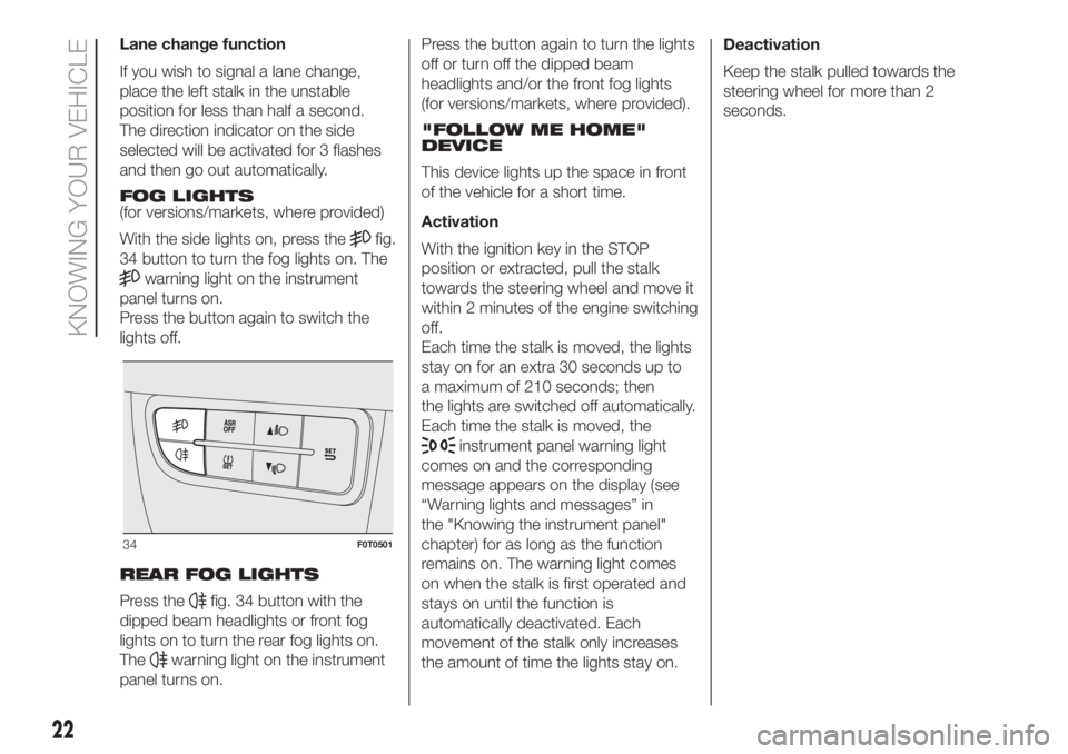
With the side lights on, press the
fig.
34 button to turn the fog lights on. The
warning light on the instrument
panel turns on.
Press the button again to switch the
lights off.
REAR FOG LIGHTS
Press the
fig. 34 button with the
dipped beam headlights or front fog
lights on to turn the rear fog lights on.
The
warning light on the instrument
panel turns on.Press the button again to turn the lights
off or turn off the dipped beam
headlights and/or the front fog lights
(for versions/markets, where provided).
"FOLLOW ME HOME"
DEVICE
This device lights up the space in front
of the vehicle for a short time.
Activation
With the ignition key in the STOP
position or extracted, pull the stalk
towards the steering wheel and move it
within 2 minutes of the engine switching
off.
Each time the stalk is moved, the lights
stay on for an extra 30 seconds up to
a maximum of 210 seconds; then
the lights are switched off automatically.
Each time the stalk is moved, the
instrument panel warning light
comes on and the corresponding
message appears on the display (see
“Warning lights and messages” in
the "Knowing the instrument panel"
chapter) for as long as the function
remains on. The warning light comes
on when the stalk is first operated and
stays on until the function is
automatically deactivated. Each
movement of the stalk only increases
the amount of time the lights stay on.Deactivation
Keep the stalk pulled towards the
steering wheel for more than 2
seconds.
34F0T0501
22
KNOWING YOUR VEHICLE
Page 33 of 196
SECURING YOUR LOAD
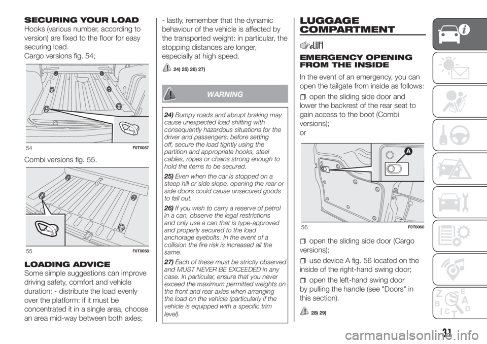
Hooks (various number, according to
version) are fixed to the floor for easy
securing load.
Cargo versions fig. 54;
Combi versions fig. 55.
LOADING ADVICE
Some simple suggestions can improve
driving safety, comfort and vehicle
duration: - distribute the load evenly
over the platform: if it must be
concentrated it in a single area, choose
an area mid-way between both axles;- lastly, remember that the dynamic
behaviour of the vehicle is affected by
the transported weight: in particular, the
stopping distances are longer,
especially at high speed.
24) 25) 26) 27)
WARNING
24)Bumpy roads and abrupt braking may
cause unexpected load shifting with
consequently hazardous situations for the
driver and passengers: before setting
off, secure the load tightly using the
partition and appropriate hooks, steel
cables, ropes or chains strong enough to
hold the items to be secured.
25)Even when the car is stopped on a
steep hill or side slope, opening the rear or
side doors could cause unsecured goods
to fall out.
26)If you wish to carry a reserve of petrol
in a can, observe the legal restrictions
and only use a can that is type-approved
and properly secured to the load
anchorage eyebolts. In the event of a
collision the fire risk is increased all the
same.
27)Each of these must be strictly observed
and MUST NEVER BE EXCEEDED in any
case. In particular, ensure that you never
exceed the maximum permitted weights on
the front and rear axles when arranging
the load on the vehicle (particularly if the
vehicle is equipped with a specific trim
level).
LUGGAGE
COMPARTMENT
EMERGENCY OPENING
FROM THE INSIDE
In the event of an emergency, you can
open the tailgate from inside as follows:
open the sliding side door and
lower the backrest of the rear seat to
gain access to the boot (Combi
versions);
or
open the sliding side door (Cargo
versions);
use device A fig. 56 located on the
inside of the right-hand swing door;
open the left-hand swing door
by pulling the handle (see "Doors" in
this section).
28) 29)
54F0T0057
55F0T0058
56F0T0060
31
Page 34 of 196

REMOVING THE PARCEL
SHELF (Combi versions)
(for versions/markets, where provided)
The parcel shelf fig. 57 consists of
two parts. To remove it completely,
proceed as follows:
open the rear swing doors and lift
the front part A fig. 57 by releasing the
pin A fig. 58 from the seat F fig. 58;
lift the rear part B fig. 57 by releasing
the pins B and C fig. 58 from the seat
D and E fig. 58.If the seat is completely folded down,
remove the parcel shelf as described
and store it horizontally between the
back of the front seats and the folded
rear seat.
To refit the parcel shelf, follow the same
procedure in reverse.
30)
EXTENDING THE BOOT
Proceed as follows:
open the rear doors and remove the
parcel shelf (as described previously);
completely lower the rear seat head
restraints;
move the seat belt to the side,
making sure that it is fully extended and
not twisted;
lift backrest retainer lever A fig. 59
and fold the backrest forwards to
obtain a flat loading area. When you lift
the lever, you will see a red band.To further expand the boot, pull tab A
fig. 60 behind the rear backrest and tip
seat and backrest forward.
REMOVING THE REAR
SEAT
The rear seat can be removed to carry
large loads and expand the boot even
further.
Combi versions
Operate the two brackets A fig. 61
under the side of the seat (one on each
side) after having tipped the rear seat
as previously described.
REPOSITIONING THE
REAR SEAT
Proceed as follows:
check that the seat belt webbing is
correctly inserted in the corresponding
bracket:
57F0T0062
58F0T0456
59F0T0921
60F0T0065
32
KNOWING YOUR VEHICLE
Page 71 of 196
Depending on the slipping conditions,
two different control systems are
activated:
if the slipping involves both drive
wheels, the ASR intervenes reducing
the power transmitted by the engine;
if the slipping only involves one
of the drive wheels, the ASR intervenes
automatically braking the wheel that
is slipping.
The action of the ASR system is
especially useful in the following
conditions:
slipping of the inner wheel round
bends due to dynamic variations in the
load of excessive acceleration;
excessive power transmitted to the
wheels, also in relation to road surface
conditions;
acceleration on slippery, snowy or
icy road surfaces;
in the case of loss of grip on a wet
surface (aquaplaning).
47) 48) 49) 50)
MSR SYSTEM (engine
drive regulation)
This is an integral part of the ESC
system that, in the event of a sudden
gear down shift or an ABS braking,
cuts in and provides torque to the
engine thus preventing excessive
driving wheel drive which, especially inpoor grip conditions, can lead to a loss
of stability.
Turning the ASR system on/off
The ASR comes on automatically
whenever the engine is started.
When travelling, the ASR system can
be switched off and on again pressing
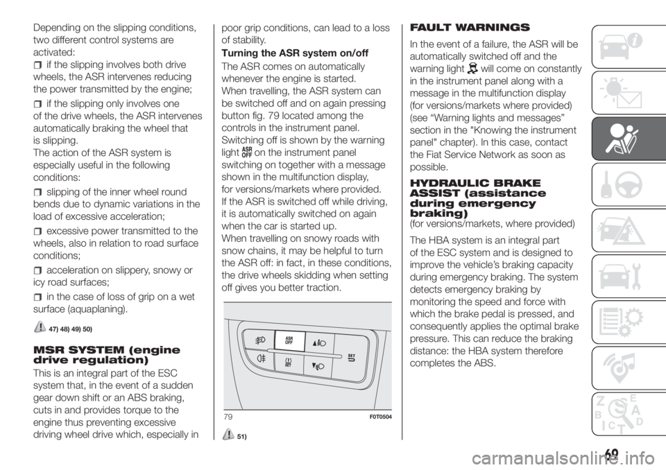
button fig. 79 located among the
controls in the instrument panel.
Switching off is shown by the warning
light
on the instrument panel
switching on together with a message
shown in the multifunction display,
for versions/markets where provided.
If the ASR is switched off while driving,
it is automatically switched on again
when the car is started up.
When travelling on snowy roads with
snow chains, it may be helpful to turn
the ASR off: in fact, in these conditions,
the drive wheels skidding when setting
off gives you better traction.
51)
FAULT WARNINGS
In the event of a failure, the ASR will be
automatically switched off and the
warning light
will come on constantly
in the instrument panel along with a
message in the multifunction display
(for versions/markets where provided)
(see “Warning lights and messages”
section in the "Knowing the instrument
panel" chapter). In this case, contact
the Fiat Service Network as soon as
possible.
HYDRAULIC BRAKE
ASSIST (assistance
during emergency
braking)
(for versions/markets, where provided)
The HBA system is an integral part
of the ESC system and is designed to
improve the vehicle’s braking capacity
during emergency braking. The system
detects emergency braking by
monitoring the speed and force with
which the brake pedal is pressed, and
consequently applies the optimal brake
pressure. This can reduce the braking
distance: the HBA system therefore
completes the ABS.
79F0T0504
69
Page 72 of 196
Maximum assistance of the HBA
system is obtained pressing the brake
pedal very quickly; in addition, the
brake pedal should be pressed
continuously during braking, avoiding
intermittent presses, to obtain benefits
from the system. Do not reduce
pressure on the brake pedal until
braking is no longer necessary. The
HBA system is deactivated when the
brake pedal is released.
52) 53) 54)
WARNING
44)The ESC system can’t overrule the
natural laws of physics, and can’t increase
the grip available according to the
condition of the road.
45)The ESC system cannot prevent
accidents, including those due to excessive
speed on corners, driving on low-grip
surfaces or aquaplaning.
46)The capability of the ESC system must
never be tested irresponsibly and
dangerously, in such a way as to
compromise personal safety and the safety
of others.
47)For the ESC and ASR systems to
function correctly, all four tyres must be the
same brand and type, must be in excellent
condition and, above all, must be of the
prescribed type and size.48)The ASR cannot overrule the natural
laws of physics, and cannot increase
the grip available according to the
condition of the road.
49)The ASR system cannot prevent
accidents, including those due to excessive
speed on corners, driving on low-grip
surfaces or aquaplaning.
50)The capability of the ASR must never
be tested irresponsibly and dangerously, in
such a way as to compromise personal
safety and the safety of others.
51)Do not take unnecessary risks, even if
your vehicle is fitted with this system.
Your driving style must always be suited to
the road conditions, visibility and traffic.
The driver is always responsible for road
safety.
52)The HBA system cannot overrule the
natural laws of physics, and cannot
increase the grip available according to the
condition of the road.
53)The HBA system cannot prevent
accidents, including those due to excessive
speed on corners, driving on low-grip
surfaces or aquaplaning.
54)The capability of the HBA must never
be tested irresponsibly and dangerously, in
such a way as to compromise personal
safety and the safety of others.
iTPMS System
(indirect Tyre
Pressure
Monitoring System)
(for versions/markets, where provided)
The indirect Tyre Pressure Monitoring
System iTPMS can monitor the tyre
inflation status through the wheel speed
sensors. The system warns the driver
if one or more tyres are flat by switching
on the
warning light on the
instrument panel and a warning
message on the display, along with an
acoustic signal.
It is advisable to check the pressure of
all four tyres. This indication is displayed
also when turning the engine off and
on until the “Reset” procedure is carried
out.
“Reset” procedure
The iTPMS needs an initial "self-
learning" phase (with length depending
on the driving style and road conditions:
optimal conditions being driving on a
straight road at 80 km/h for at least 20
minutes) which starts when the “Reset”
procedure is carried out.
The “Reset” procedure must be carried
out:
each time tyre pressure is modified;
when even only one tyre is changed;
when tyres are rotated/inverted;
70
SAFETY
Page 73 of 196
when the space-saver wheel is
fitted. Before carrying out the “Reset”
procedure, inflate the tyres to the rated
pressure values specified in the inflation
pressure table (see "Wheels" paragraph
in the "Technical specifications"
chapter).
If the “Reset” procedure is not carried
out, in all above cases, the
warning
light may give false indications on
one or more tyres.
To carry out the “Reset” procedure,
with the vehicle stopped and the
ignition device at MAR, use the Setup
Menu as follows:
briefly press thebutton: the
display will show "Reset";
press thebutton or the
button to select ("Yes" or "No");
briefly press thebutton: the
display will show "Confirm";
pressbutton orto select
("Yes" to “Reset” or "No" to exit the
video page);
press thebutton again to return
to the standard screen or to the main
menu according to where you are in the
menu.
After the “Reset” the display will show
the "Reset saved" message, indicating
that the "self-learning" has been
started.Operating conditions
The system is active for speeds above
15 km/h. In a few situations such as
sporty driving, particular conditions of
the road surface (e.g. icy, snowy,
unsurfaced roads...) the signalling may
be delayed or partial in detecting the
contemporary deflation of more than
one tyre. Under special conditions (e.g.
vehicle loaded asymmetrically on one
side, towing a trailer, damaged or worn
tyre, fitting the space-saver wheel,
use of the "Fix&Go Automatic"
kit, fitting snow chains, fitting different
tyres on the axles) the system may give
false indications or be temporarily
deactivated.
If the system is temporarily deactivated,
the warning light
flashes for about
75 seconds and then is continuously
on; at the same time, the display shows
a dedicated message. This warning is
displayed also after the engine has
been switched off and then on again if
the correct operating conditions are not
restored.
55) 56) 57) 58) 59)
12) 13) 14) 15) 16) 17) 18) 19) 20)
WARNING
55)The system is an aid for the driver, who
must always pay full attention while
driving. The responsibility always rests with
the driver, who must take into account
the traffic conditions in order to drive
in complete safety. The driver must always
maintain a safe distance from the vehicle
in front.
56)If the driver depresses the brake pedal
fully or carries out a fast steering during
system operation, the automatic braking
function may stop (e.g. to allow a possible
manoeuvre to avoid the obstacle).
57)The laser beam is not visible at the
naked eye. Do not look directly, or with
optical instruments (e.g. lenses), at the
laser beam from a distance lower than 10
cm: this may cause damage to the sight.
The laser beam is also present when
the key is at MAR but its operation is off,
not available or manually deactivated
with the display Setup Menu.
58)The system intervenes on vehicles
travelling in the same lane. Small sized
vehicles (e.g. bicycles or motorbikes)
or people, animals and things (e.g.
pushchairs) and more in general all those
obstacles with a low reflection of the light
emitted by the laser (e.g. vehicles soiled
with mud) are not taken into consideration.
71
Page 75 of 196
Traction Plus operation
The system is deactivated when
starting. To activate the "Traction Plus"
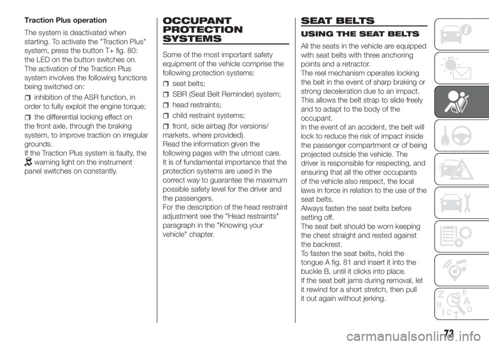
system, press the button T+ fig. 80:
the LED on the button switches on.
The activation of the Traction Plus
system involves the following functions
being switched on:
inhibition of the ASR function, in
order to fully exploit the engine torque;
the differential locking effect on
the front axle, through the braking
system, to improve traction on irregular
grounds.
If the Traction Plus system is faulty, the
warning light on the instrument
panel switches on constantly.
OCCUPANT
PROTECTION
SYSTEMS
Some of the most important safety
equipment of the vehicle comprise the
following protection systems:
seat belts;
SBR (Seat Belt Reminder) system;
head restraints;
child restraint systems;
front, side airbag (for versions/
markets, where provided).
Read the information given the
following pages with the utmost care.
It is of fundamental importance that the
protection systems are used in the
correct way to guarantee the maximum
possible safety level for the driver and
the passengers.
For the description of the head restraint
adjustment see the "Head restraints"
paragraph in the "Knowing your
vehicle" chapter.
SEAT BELTS
USING THE SEAT BELTS
All the seats in the vehicle are equipped
with seat belts with three anchoring
points and a retractor.
The reel mechanism operates locking
the belt in the event of sharp braking or
strong deceleration due to an impact.
This allows the belt strap to slide freely
and to adapt to the body of the
occupant.
In the event of an accident, the belt will
lock to reduce the risk of impact inside
the passenger compartment or of being
projected outside the vehicle. The
driver is responsible for respecting, and
ensuring that all the other occupants
of the vehicle also respect, the local
laws in force in relation to the use of the
seat belts.
Always fasten the seat belts before
setting off.
The seat belt should be worn keeping
the chest straight and rested against
the backrest.
To fasten the seat belts, hold the
tongue A fig. 81 and insert it into the
buckle B, until it clicks into place.
If the seat belt jams during removal, let
it rewind for a short stretch, then pull
it out again without jerking.
73
Page 77 of 196
SBR SYSTEM
(for versions/markets, where provided)
The vehicle is equipped with a system
called S.B.R. (Seat Belt Reminder),
which warns the driver and front
passenger if their seat belt is not
fastened, as follows:
warning lightcomes on in the
instrument panel and the buzzer
sounds continuously for the first 6
seconds;
warning lightflashes in the
instrument panel and the buzzer
sounds intermittently for the following
90 seconds.
For permanent deactivation, contact a
Fiat Dealership.
The SBR system can also be
reactivated through the setup menu.
PRE-TENSIONERS
To increase the protective efficiency of
the front seat belts, the vehicle is fitted
with pretensioners. These devices, in
the event of a violent frontal collision or
side collision, rewind the seat belts a
few centimetres. In this way, they
ensure that the belts fit tightly to the
wearer before the restraining action
begins.
It is evident that the pretensioners have
been activated when the belt withdraws
toward the retractor.
IMPORTANT To obtain the highest
degree of protection from the action of
the pretensioner, wear the seat belt
tight to the chest and pelvis.
A slight discharge of smoke may be
produced during the activation of the
pretensioner which is not harmful and
does not involve any fire hazard.
The pretensioner does not require any
maintenance or lubrication. Any
changes to its original conditions will
invalidate its efficiency. If, due to
unusual natural events (floods, sea
storms, etc.), the device has been
affected by water and mud, it must
absolutely be replaced.
63) 64)
21)
LOAD LIMITERS
(for versions/markets, where provided)
To increase occupant safety in an
accident, the front seat belt reels on
driver side and passenger side (for
versions/markets, where provided)
contain a device which controls the
force acting on the chest and shoulders
during the restraining action of the
belts in the event of a frontal collision.
GENERAL
INSTRUCTIONS FOR
USING THE SEAT BELTS
The driver is responsible for respecting,
and ensuring that all the other
occupants of the vehicle also respect,
the local laws in force in relation to
the use of the seat belts. Always fasten
the seat belts before setting off.
Seat belts are also to be worn by
pregnant women: the risk of injury in
the case of impact is greatly reduced
for them and the unborn child if they
are wearing a seat belt. Pregnant
women must position the lower part of
the belt very low down so that it passes
over the pelvis and under the
abdomen (see fig. 85).
While pregnancy progresses, the driver
must adjust both the seat and the
steering wheel to ensure full control of
the vehicle (pedals and steering wheel
must be easily accessible).
75