FIAT FREEMONT 2011 Owner handbook (in English)
Manufacturer: FIAT, Model Year: 2011, Model line: FREEMONT, Model: FIAT FREEMONT 2011Pages: 267, PDF Size: 5.16 MB
Page 61 of 267
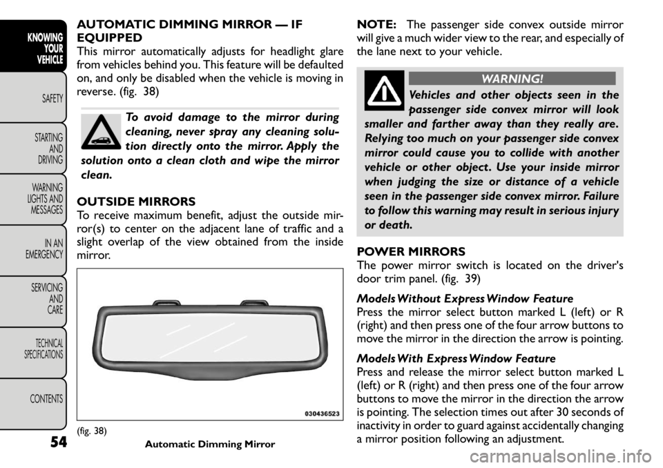
AUTOMATIC DIMMING MIRROR — IF EQUIPPED
This mirror automatically adjusts for headlight glare
from vehicles behind you. This feature will be defaulted
on, and only be disabled when the vehicle is moving in
reverse. (fig. 38)
To avoid damage to the mirror during
cleaning, never spray any cleaning solu-
tion directly onto the mirror. Apply the
solution onto a clean cloth and wipe the mirrorclean.
OUTSIDE MIRRORS
To receive maximum benefit, adjust the outside mir-
ror(s) to center on the adjacent lane of traffic and a
slight overlap of the view obtained from the inside
mirror. NOTE:
The passenger side convex outside mirror
will give a much wider view to the rear, and especially of
the lane next to your vehicle.
WARNING!
Vehicles and other objects seen in the
passenger side convex mirror will look
smaller and farther away than they really are.
Relying too much on your passenger side convex
mirror could cause you to collide with another
vehicle or other object . Use your inside mirror
when judging the size or distance of a vehicle
seen in the passenger side convex mirror. Failure
to follow this warning may result in serious injury
or death.
POWER MIRRORS
The power mirror switch is located on the driver's
door trim panel. (fig. 39)
Models Without Express Window Feature
Press the mirror select button marked L (left) or R
(right) and then press one of the four arrow buttons to
move the mirror in the direction the arrow is pointing.
Models With Express Window Feature
Press and release the mirror select button marked L
(left) or R (right) and then press one of the four arrow
buttons to move the mirror in the direction the arrow
is pointing. The selection times out after 30 seconds of
inactivity in order to guard against accidentally changing
a mirror position following an adjustment.
(fig. 38) Automatic Dimming Mirror
54
KNOWING
YOUR
VEHICLE
SAFETY
STARTING AND
DRIVING
WARNING
LIGHTS AND
MESSAGES
IN AN
EMERGENCY
SERVICING AND
CARETECHNICAL
SPECIFICATIONSCONTENTS
Page 62 of 267

NOTE:A light in the selected button will illuminate
indicating the mirror is activated and can be adjusted.
POWER FOLDING MIRRORS — IF EQUIPPED
The switch for the power folding mirrors is located
between the power mirror switches L (left) and R
(right). Press the switch once and the mirrors will fold
in, pressing the switch a second time will return the
mirrors to the normal driving position.
NOTE: Pressing the power folding mirror switch for
more than four seconds, or if the vehicle speed is
greater than 8 km/h will disable the folding feature.
If the mirrors are in the folded position, and vehicle
speed is equal or greater than 8 km/h, they will auto-
matically unfold. MANUAL FOLDING MIRRORS — IFEQUIPPED
Some models have exterior mirrors that are hinged.
The hinge allows the mirror to pivot forward and
rearward to resist damage. The hinge has three detent
positions: forward, rearward and normal.
HEATED MIRRORS — IF EQUIPPED
These mirrors are heated to melt frost or ice.
This feature is activated whenever you turn on
the rear window defroster. Refer to “Rear Window
Features” for further information.
ILLUMINATED VANITY MIRRORS — IF EQUIPPED
An illuminated vanity mirror is on each sun visor. To use
the mirror, rotate the sun visor downward and swing
the mirror cover upward. The light will turn on auto-
matically. Closing the mirror cover will turn off the
light. (fig. 40)
Sun Visor “Slide-On Rod” Feature — If
Equipped
This feature allows for additional flexibility in position-
ing the visor to block out the sun.
1. Fold down the sun visor.
2. Unclip the visor from the center clip.
3. Pull the sun visor toward the inside rearview mirror
to extend it.(fig. 39) Power Mirror Switches
55KNOWING
YOURVEHICLESAFETY
STARTING ANDDRIVING
WARNING
LIGHTS AND
MESSAGES
IN AN
EMERGENCY
SERVICING AND
CARETECHNICAL
SPECIFICATIONSCONTENTS
Page 63 of 267
CLIMATE CONTROLS
GENERAL OVERVIEW
The air conditioning and heating system is designed to
make you comfortable in all types of weather. This
system can be operated through either the Automatic
Climate Controls on the instrument panel or through
the Uconnect Touch™ system display.
When the Uconnect Touch™ system is in different
modes (Radio, Player, Settings, More, etc.) the driver
and passenger temperature settings will be indicated at
the top of the display.
Hard-Keys
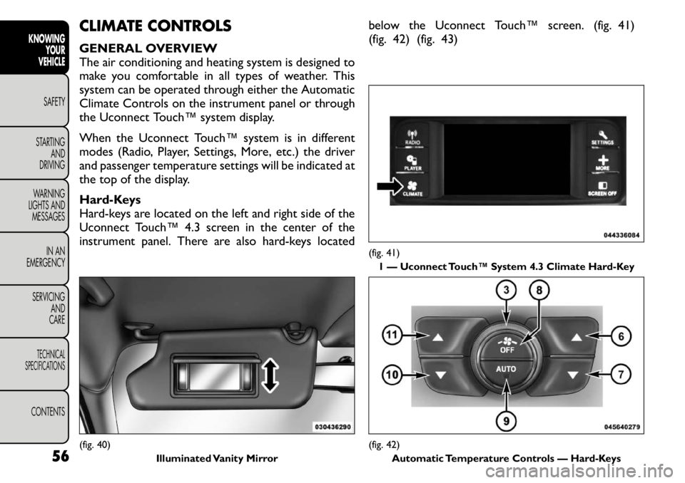
Hard-keys are located on the left and right side of the
Uconnect Touch™ 4.3 screen in the center of the
instrument panel. There are also hard-keys locatedbelow the Uconnect Touch™ screen. (fig. 41)
(fig. 42) (fig. 43)(fig. 40)
Illuminated Vanity Mirror
(fig. 41)
1 — Uconnect Touch™ System 4.3 Climate Hard-Key(fig. 42) Automatic Temperature Controls — Hard-Keys
56
KNOWING
YOUR
VEHICLE
SAFETY
STARTING AND
DRIVING
WARNING
LIGHTS AND
MESSAGES
IN AN
EMERGENCY
SERVICING AND
CARETECHNICAL
SPECIFICATIONSCONTENTS
Page 64 of 267
Soft-Keys
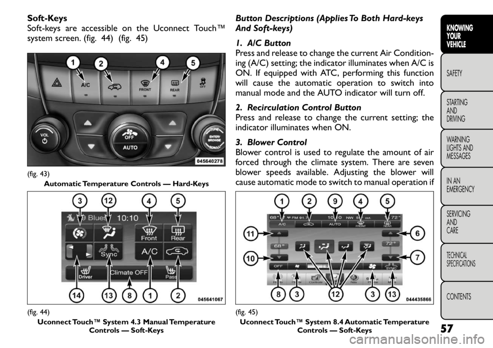
Soft-keys are accessible on the Uconnect Touch™
system screen. (fig. 44) (fig. 45)Button Descriptions (Applies To Both Hard-keys
And Soft-keys)
1. A/C Button
Press and release to change the current Air Condition-
ing (A/C) setting; the indicator illuminates when A/C is
ON. If equipped with ATC, performing this function
will cause the automatic operation to switch into
manual mode and the AUTO indicator will turn off.
2. Recirculation Control Button
Press and release to change the current setting; the
indicator illuminates when ON.
3. Blower Control
Blower control is used to regulate the amount of air
forced through the climate system. There are seven
blower speeds available. Adjusting the blower will
cause automatic mode to switch to manual operation if(fig. 43)
Automatic Temperature Controls — Hard-Keys(fig. 44)Uconnect Touch™ System 4.3 Manual Temperature Controls — Soft-Keys
(fig. 45)
Uconnect Touch™ System 8.4 Automatic Temperature Controls — Soft-Keys 57
KNOWING
YOURVEHICLESAFETY
STARTING ANDDRIVING
WARNING
LIGHTS AND
MESSAGES
IN AN
EMERGENCY
SERVICING AND
CARETECHNICAL
SPECIFICATIONSCONTENTS
Page 65 of 267
equipped with ATC. The speeds can be selected using
either hard-heys or soft-keys as follows:
Hard-Keys
The blower speed increases as you turn the control
clockwise from the lowest blower setting. The blower
speed decreases as you turn the knob counter-
clockwise.
Soft-Key — Uconnect Touch™ System 4.3
Press the blower soft-key to enter the blower setting
screen. Once in the blower setting screen, use the UP
and DOWN arrows to adjust the blower speed setting,
or directly select the speed setting by pressing the
blower bar area around the blower icon. The blower
speed increases as you press the UP arrow or move
clockwise on the setting scale and decreases when you
press the DOWN arrow or move counter-clockwise
on the setting scale.
Soft-Key — Uconnect Touch™ System 8.4
Use the small blower icon to reduce the blower setting
and the large blower icon to increase the blower
setting. Blower can also be selected by pressing the
blower bar area between the icons.
4. Front Defrost Button
Press and release to change the current airflow setting
to Defrost mode. The indicator illuminates when this
feature is ON. Performing this function will cause the
ATC (if equipped) to switch into manual mode. The
blower speed may increase when Defrost mode is
selected. If the front defrost mode is turned off, the
climate system will return the previous setting.5. Rear Defrost Button
Press and release this button to turn on the rear
window defroster and the heated outside mirrors (if
equipped). An indicator will illuminate when the rear
window defroster is on. The rear window defroster
automatically turns off after 10 minutes.
Failure to follow these cautions can
cause damage to the heating elements:
Use care when washing the inside of
the rear window. Do not use abrasive window
cleaners on the interior surface of the window.
Use a soft cloth and a mild washing solution,
wiping parallel to the heating elements. Labels
can be peeled off after soaking with warm water.
Do not use scrapers, sharp instruments, or abra-
sive window cleaners on the interior surface of
the window.
Keep all objects a safe distance from the
window.
6. Passenger Temperature Control Up Button
Provides the passenger with independent temperature
control. Push the button for warmer temperaturesettings.
NOTE: Pressing this button while in Sync mode will
automatically exit Sync.
58
KNOWING YOUR
VEHICLE
SAFETY
STARTING AND
DRIVING
WARNING
LIGHTS AND
MESSAGES
IN AN
EMERGENCY
SERVICING AND
CARETECHNICAL
SPECIFICATIONSCONTENTS
Page 66 of 267
7. Passenger Temperature Control Down Button
Provides the passenger with independent temperature
control. Push the button for cooler temperature set-tings.
NOTE:Pressing this button while in Sync mode will
automatically exit Sync.
8. Climate Control OFF Button
Press and release this button to turn the Climate
Control ON/OFF.
9. AUTO Operation Button — If Equipped
Automatically controls the interior cabin temperature
by adjusting airflow distribution and amount. Perform-
ing this function will cause the ATC to switch between
manual mode and automatic modes. Refer to “Auto-
matic Operation” for more information.
10. Driver Temperature Control Down Button
Provides the driver with independent temperature
control. Push the button for cooler temperature set-tings.
NOTE: In Sync mode, this button will also automati-
cally adjust the passenger and rear temperature setting
at the same time.
11. Driver Temperature Control Up Button
Provides the driver with independent temperature
control. Push the button for warmer temperaturesettings. NOTE:
In Sync mode, this button will also automati-
cally adjust the passenger and rear temperature setting
at the same time.
12. Modes
The airflow distribution mode can be adjusted so air
comes from the instrument panel outlets, floor outlets,
demist outlets and defrost outlets. The Mode settings
are as follows: Panel Mode
Air comes from the outlets in the instrument
panel. Each of these outlets can be individually
adjusted to direct the flow of air. The air vanes of the
center outlets and outboard outlets can be moved up
and down or side-to-side to regulate airflow direction.
There is a shut off wheel, located below the air vanes,
to shut off or adjust the amount of airflow from theseoutlets. Bi-Level Mode
Air comes from the instrument panel outlets and
floor outlets. A slight amount of air is directed
through the defrost and side window demister outlets.
NOTE: BI-LEVEL mode is designed under comfort
conditions to provide cooler air out of the panel
outlets and warmer air from the floor outlets. Floor Mode
Air comes from the floor outlets. A slight amount
of air is directed through the defrost and side
window demister outlets.
59KNOWING
YOURVEHICLESAFETY
STARTING ANDDRIVING
WARNING
LIGHTS AND
MESSAGES
IN AN
EMERGENCY
SERVICING AND
CARETECHNICAL
SPECIFICATIONSCONTENTS
Page 67 of 267
Mix Mode
Air comes from the floor, defrost and side win-
dow demist outlets. This mode works best in
cold or snowy conditions.
Defrost Mode
Air comes from the windshield and side window
demist outlets. Use Defrost mode with maxi-
mum temperature settings for best windshield and side
window defrosting and defogging. When the Defrost
mode is selected, the blower level may increase.
13. SYNC
Press the Sync soft-key to toggle the Sync feature
On/Off. The Sync indicator is illuminated when this
feature is enabled. Sync is used to synchronize the
passenger and rear temperature setting with the driver
temperature setting. Changing the passenger tempera-
ture setting while in Sync will automatically exit this
feature.
NOTE: When SYNC is ON and the driver selects
Mix or Defrost Mode, Rear mode will be Floor.
14. Temperature Control (Manual Temperature
Control Only)
Press the temperature soft-key to regulate the tem-
perature of the air inside the passenger compartment.
Moving the temperature bar into the red area, indicates
warmer temperatures. Moving the temperature bar
into the blue area indicates cooler temperatures. CLIMATE CONTROL FUNCTIONS
A/C (Air Conditioning)
The Air Conditioning (A/C) button allows the opera-
tor to manually activate or deactivate the air condition-
ing system. When the air conditioning system is turned
on, cool dehumidified air will flow through the outlets
into the cabin. For improved fuel economy, press the
A/C button to turn off the air conditioning and manu-
ally adjust the blower and airflow mode settings.
NOTE:
• For Manual Climate Controls, if the system is in Mix
or Defrost Mode, the A/C can be turned off.
• If fog or mist appears on the windshield or side glass,
select Defrost mode and increase blower speed.
• If your air conditioning performance seems lower
than expected, check the front of the A/C condenser
(located in front of the radiator), for an accumulation of
dirt or insects. Clean with a gentle water spray from
behind the radiator and through the condenser. Fabric
front fascia protectors may reduce airflow to the con-
denser, reducing air conditioning performance.
Recirculation Control
When outside air contains smoke, odors, or
high humidity, or if rapid cooling is desired,
you may wish to recirculate interior air by
pressing the Recirculation control button.
The recirculation indicator will illuminate when this
button is selected. Push the button a second time to
60
KNOWING YOUR
VEHICLE
SAFETY
STARTING AND
DRIVING
WARNING
LIGHTS AND
MESSAGES
IN AN
EMERGENCY
SERVICING AND
CARETECHNICAL
SPECIFICATIONSCONTENTS
Page 68 of 267
turn off the Recirculation mode and allow outside air
into the vehicle.
NOTE:In cold weather, use of Recirculation mode
may lead to excessive window fogging. The Recircula-
tion mode is not allowed in Mix, Floor and Defrost
modes to improve window clearing operation. Recir-
culation will be disabled automatically if these modes
are selected. Attempting to use Recirculation while in
these modes will cause the LED in the control button
to blink and then turn off.
AUTOMATIC TEMPERATURE CONTROL
(ATC)
ATC Hard-keys are located in the center of the instru-
ment panel.
Soft-keys are accessible on the Uconnect Touch™
system screen.
Automatic Operation
1. Press the AUTO hard-key or soft-key button (9) on the Automatic Temperature Control (ATC) Panel.
2. Next, adjust the temperature you would like the system to maintain by adjusting the driver and pas-
senger temperature hard or soft control buttons (6,
7, 10, 11). Once the desired temperature is dis-
played, the system will achieve and automatically
maintain that comfort level.
3. When the system is set up for your comfort level, it is not necessary to change the settings. You will
experience the greatest efficiency by simply allowing
the system to function automatically. NOTE:
• It is not necessary to move the temperature settings
for cold or hot vehicles. The system automatically
adjusts the temperature, mode and blower speed to
provide comfort as quickly as possible.
• The temperature can be displayed in U.S. or Metric
units by selecting the US/M customer-programmable
feature. Refer to the “Uconnect Touch™ System Set-
tings” in this section of the manual.
To provide you with maximum comfort in the Auto-
matic mode, during cold start-ups the blower fan will
remain on low until the engine warms up. The blower
will increase in speed and transition into Auto mode.
Manual Operation
The system allows for manual selection of blower
speed, air distribution mode, A/C status and recircula-
tion control.
The blower fan speed can be set to any fixed speed by
adjusting the blower control. The fan will now operate
at a fixed speed until additional speeds are selected.
This allows the front occupants to control the volume
of air circulated in the vehicle and cancel the Auto
mode.
The operator can also select the direction of the
airflow by selecting one of the available mode settings.
A/C operation and Recirculation control can also be
manually selected in Manual operation.
61
KNOWING
YOURVEHICLESAFETY
STARTING ANDDRIVING
WARNING
LIGHTS AND
MESSAGES
IN AN
EMERGENCY
SERVICING AND
CARETECHNICAL
SPECIFICATIONSCONTENTS
Page 69 of 267

REAR AUTOMATIC TEMPERATURE
CONTROL (ATC) — IF EQUIPPED
The rear ATC system has floor air outlets at the rear
right side of the 3rd Row seats and overhead outlets at
each outboard rear seating position. The system pro-
vides heated air through the floor outlets or cool,
dehumidified air through the headliner outlets.
The rear system temperature control is in the
Uconnect Touch™ system, located on the instrument
panel. (fig. 46) (fig. 47)Rear Lock
Pressing the Rear Temperature Lock soft-key on the
Uconnect Touch™ screen, illuminates a lock symbol in
the rear display. The rear temperature and air source
are controlled from the front Uconnect Touch™ sys-
tem.
Rear second row occupants can only adjust the rear
ATC control when the Rear Temperature Lock button
is turned off.
The rear ATC is located in the headliner, near the
center of the vehicle. (fig. 48)(fig. 46)
Rear Climate Controls 4.3 Screen
1 — Blower Up Soft-Key 5 — Done Soft-Key
2 — Mode Soft-Key 6 — Rear Lock Soft-Key
3 — Temperature Soft-Key 7 — Rear Off Soft-Key
4 — Blower Down Soft-Key
(fig. 47) Rear Climate Controls 8.4 Screen
1 — Rear Auto Soft-Key 6 — Blower Up Soft-Key
2 — Rear Lock Soft-Key 7 — Mode Soft-Key
3 — Front Climate Soft-Key 8 — Blower Down Soft-Key
4 — Temperature Up
Soft-Key 9 — Rear Off Soft-Key
5— Temperature Down
Soft-Key
62
KNOWING
YOUR
VEHICLE
SAFETY
STARTING AND
DRIVING
WARNING
LIGHTS AND
MESSAGES
IN AN
EMERGENCY
SERVICING AND
CARETECHNICAL
SPECIFICATIONSCONTENTS
Page 70 of 267
• Press the Rear Temperature Lock button on theUconnect Touch™ screen. This turns off the Rear
Temperature Lock icon in the rear temperature
knob.
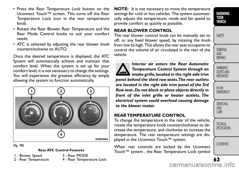
• Rotate the Rear Blower, Rear Temperature and the Rear Mode Control knobs to suit your comfortneeds.
• ATC is selected by adjusting the rear blower knob counterclockwise to AUTO.
Once the desired temperature is displayed, the ATC
System will automatically achieve and maintain that
comfort level. When the system is set up for your
comfort level, it is not necessary to change the settings.
You will experience the greatest efficiency by simply
allowing the system to function automatically. NOTE:
It is not necessary to move the temperature
settings for cold or hot vehicles. The system automati-
cally adjusts the temperature, mode and fan speed to
provide comfort as quickly as possible.
REAR BLOWER CONTROL
The rear blower control knob can be manually set to
off, or any fixed blower speed, by rotating the knob
from low to high. This allows the rear seat occupants to
control the volume of air circulated in the rear of the
vehicle.
Interior air enters the Rear Automatic
Temperature Control System through an
intake grille, located in the right side trim
panel behind the third row seats.The rear outlets
are located in the right side trim panel of the 3rd
Row seat . Do not block or place objects directly in
front of the inlet grille or heater outlets. The
electrical system could overload causing damage
to the blower motor.
REAR TEMPERATURE CONTROL
To change the temperature in the rear of the vehicle,
rotate the temperature knob counterclockwise to de-
crease the temperature, and clockwise to increase the
temperature. The rear temperature settings are dis-
played in the Uconnect Touch™ system.
When rear controls are locked by the Uconnect
Touch™ system , the Rear Temperature Lock symbol
(fig. 48) Rear ATC Control Features
1 - Blower Speed 3 - Rear MODE
2 - Rear Temperature 4 - Rear Temperature Lock 63
KNOWING
YOURVEHICLESAFETY
STARTING ANDDRIVING
WARNING
LIGHTS AND
MESSAGES
IN AN
EMERGENCY
SERVICING AND
CARETECHNICAL
SPECIFICATIONSCONTENTS