steering FIAT FREEMONT 2011 Owner handbook (in English)
[x] Cancel search | Manufacturer: FIAT, Model Year: 2011, Model line: FREEMONT, Model: FIAT FREEMONT 2011Pages: 267, PDF Size: 5.16 MB
Page 8 of 267

KNOWING YOUR VEHICLE
INTRODUCTION
Congratulations on selecting your new FIAT vehicle. Be
assured that it represents precision workmanship, dis-
tinctive styling, and high quality - all essentials that are
traditional to our vehicles.
Before you start to drive this vehicle, read this Owner's
Manual and all the supplements. Be sure you are familiar
with all vehicle controls, particularly those used for
braking, steering, and transmission shifting. Learn how
your vehicle handles on different road surfaces. Your
driving skills will improve with experience, but as in
driving any vehicle, take it easy as you begin. Always
observe local laws wherever you drive.
NOTE: After reviewing the owner information,
it should be stored in the vehicle for convenient
referencing and remain with the vehicle whensold.
Failure to operate this vehicle correctly may result in
loss of control or a collision. Operating this vehicle at excessive speeds or while
intoxicated may result in loss of control, collision with
other vehicles or objects, going off the road, or over-
turning; any of which may lead to serious injury or
death. Also, failure to use seat belts subjects the driver
and passengers to a greater risk of injury or death.
To keep your vehicle running at its best, have your
vehicle serviced at recommended intervals by an au-
thorized dealer who has the qualified personnel, special
tools, and equipment to perform all service.
The manufacturer and its distributors are vitally inter-
ested in your complete satisfaction with this vehicle. If
you encounter a service or warranty problem, which is
not resolved to your satisfaction, discuss the matter
with your dealer's management.
Your authorized dealer will be happy to assist you with
any questions about your vehicle.
1
KNOWING
YOURVEHICLESAFETY
STARTING ANDDRIVING
WARNING
LIGHTS AND
MESSAGES
IN AN
EMERGENCY
SERVICING AND
CARETECHNICAL
SPECIFICATIONSCONTENTS
Page 24 of 267

• For vehicles equipped with Keyless Enter-N-Go,press the Keyless Enter-N-Go Start/Stop button
(requires at least one valid Key Fob in the vehicle).
• For vehicles not equipped with Keyless Enter-N- Go, insert a valid key into the ignition switch and
turn the key to the ON position.
NOTE:
• The driver's door key cylinder and the liftgate button
on the RKE transmitter cannot arm or disarm the
Vehicle Security Alarm.
• When the Vehicle Security Alarm is armed, the
interior power door lock switches will not unlock thedoors.
The Vehicle Security Alarm is designed to protect your
vehicle; however, you can create conditions where the
system will give you a false alarm. If one of the previ-
ously described arming sequences has occurred, the
Vehicle Security Alarm will arm regardless of whether
you are in the vehicle or not. If you remain in the
vehicle and open a door, the alarm will sound. If this
occurs, disarm the Vehicle Security Alarm.
If the Vehicle Security Alarm is armed and the battery
becomes disconnected, the Vehicle Security Alarm will
remain armed when the battery is reconnected; the
exterior lights will flash, the horn will sound. If this
occurs, disarm the Vehicle Security Alarm.
Security System Manual Override
The system will not arm if you lock the doors using the
manual door lock plunger. STEERING WHEEL LOCK — IF EQUIPPED
Your vehicle may be equipped with a passive electronic
steering wheel lock. This lock prevents steering the
vehicle without the ignition key. The steering wheel
lock has six positions (one every 60 degrees). If the
steering wheel is moved to one of these six position
with the key in the off positions, the steering wheel will
lock.
TO MANUALLY LOCK THE STEERING WHEEL
With the engine running, rotate the steering wheel
one-half revolution, turn off the engine and remove the
key. Turn the steering wheel slightly in either direction
until the lock engages.
TO RELEASE THE STEERING WHEEL LOCK
Cycle the ignition and start the engine.
NOTE:
If you turned the wheel to the right to engage
the lock, you must turn the wheel slightly to the right
to disengage it. If you turned the wheel to the left to
engage the lock, turn the wheel slightly to the left to
disengage it.
17
KNOWING
YOURVEHICLESAFETY
STARTING ANDDRIVING
WARNING
LIGHTS AND
MESSAGES
IN AN
EMERGENCY
SERVICING AND
CARETECHNICAL
SPECIFICATIONSCONTENTS
Page 25 of 267
ELECTRONIC VEHICLE
INFORMATION CENTER (EVIC)
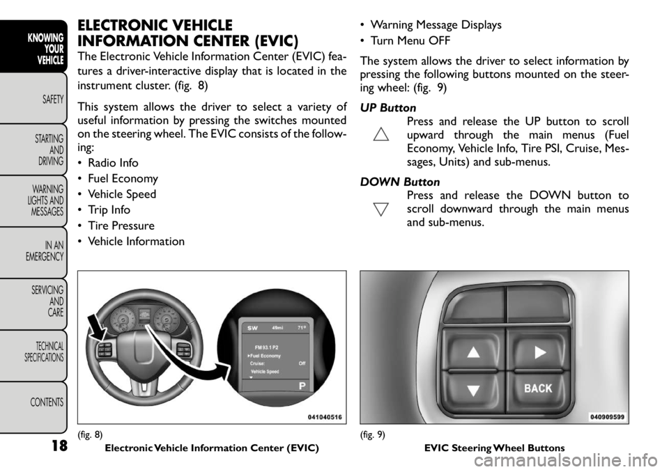
The Electronic Vehicle Information Center (EVIC) fea-
tures a driver-interactive display that is located in the
instrument cluster. (fig. 8)
This system allows the driver to select a variety of
useful information by pressing the switches mounted
on the steering wheel. The EVIC consists of the follow-ing:
• Radio Info
• Fuel Economy
• Vehicle Speed
• Trip Info
• Tire Pressure
• Vehicle Information• Warning Message Displays
• Turn Menu OFF
The system allows the driver to select information by
pressing the following buttons mounted on the steer-
ing wheel: (fig. 9)
UP Button
Press and release the UP button to scroll
upward through the main menus (Fuel
Economy, Vehicle Info, Tire PSI, Cruise, Mes-
sages, Units) and sub-menus.
DOWN Button Press and release the DOWN button to
scroll downward through the main menus
and sub-menus.(fig. 8)Electronic Vehicle Information Center (EVIC)
(fig. 9) EVIC Steering Wheel Buttons
18
KNOWINGYOUR
VEHICLE
SAFETY
STARTING AND
DRIVING
WARNING
LIGHTS AND
MESSAGES
IN AN
EMERGENCY
SERVICING AND
CARETECHNICAL
SPECIFICATIONSCONTENTS
Page 59 of 267
WARNING!
Be certain that the seatback is locked
securely into position. Otherwise, the
seat will not provide the proper stability for
passengers. An improperly latched seat could
cause serious injury.
Do not allow a passenger to sit in a third row
seat without having the head restraint unfolded
and locked in place. Failure to follow this warning
may result in personal injury to the passenger in
the event of a collision.
Do not allow a passenger to sit in a third row
seat with the second row seatback(s) folded flat .
In a collision, the passenger could slide under-
neath the seat belt and be seriously or even
fatally injured. TILT/TELESCOPING STEERING
COLUMN
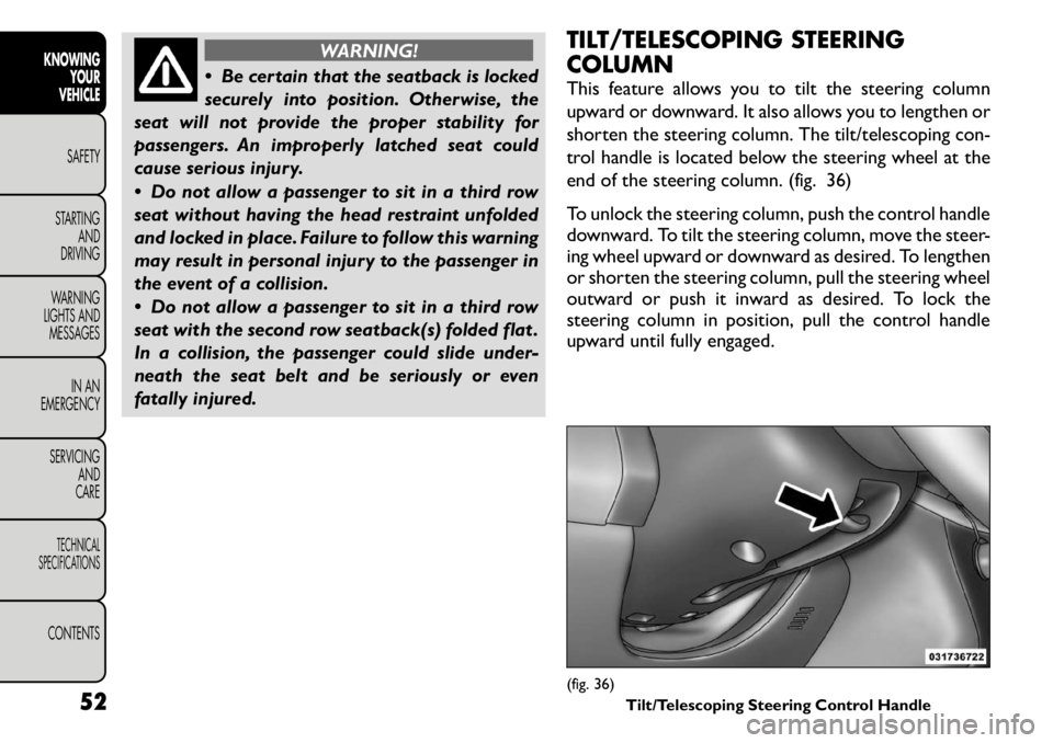
This feature allows you to tilt the steering column
upward or downward. It also allows you to lengthen or
shorten the steering column. The tilt/telescoping con-
trol handle is located below the steering wheel at the
end of the steering column. (fig. 36)
To unlock the steering column, push the control handle
downward. To tilt the steering column, move the steer-
ing wheel upward or downward as desired. To lengthen
or shorten the steering column, pull the steering wheel
outward or push it inward as desired. To lock the
steering column in position, pull the control handle
upward until fully engaged.
(fig. 36)
Tilt/Telescoping Steering Control Handle
52
KNOWING
YOUR
VEHICLE
SAFETY
STARTING AND
DRIVING
WARNING
LIGHTS AND
MESSAGES
IN AN
EMERGENCY
SERVICING AND
CARETECHNICAL
SPECIFICATIONSCONTENTS
Page 60 of 267
WARNING!
Do not adjust the steering column while
driving. Adjusting the steering column
while driving or driving with the steering column
unlocked could cause the driver to lose control of
the vehicle. Be sure the steering column is locked
before driving your vehicle. Failure to follow this
warning may result in serious injury or death. MIRRORS
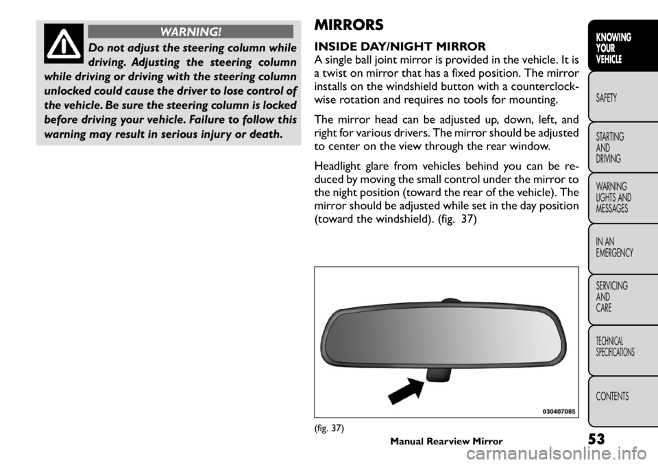
INSIDE DAY/NIGHT MIRROR
A single ball joint mirror is provided in the vehicle. It is
a twist on mirror that has a fixed position. The mirror
installs on the windshield button with a counterclock-
wise rotation and requires no tools for mounting.
The mirror head can be adjusted up, down, left, and
right for various drivers. The mirror should be adjusted
to center on the view through the rear window.
Headlight glare from vehicles behind you can be re-
duced by moving the small control under the mirror to
the night position (toward the rear of the vehicle). The
mirror should be adjusted while set in the day position
(toward the windshield). (fig. 37)
(fig. 37)
Manual Rearview Mirror 53
KNOWING
YOURVEHICLESAFETY
STARTING ANDDRIVING
WARNING
LIGHTS AND
MESSAGES
IN AN
EMERGENCY
SERVICING AND
CARETECHNICAL
SPECIFICATIONSCONTENTS
Page 75 of 267

NOTE:The fog lights will operate with the low beam
headlights or parking lights on. However, selecting the
high beam headlights will turn off the fog lights.
MULTIFUNCTION LEVER
The multifunction lever controls the operation of the
turn signals, headlight beam selection and passing lights.
The multifunction lever is located on the left side of the
steering column.
TURN SIGNALS
Move the multifunction lever up or down and the
arrows on each side of the instrument cluster flash to
show proper operation of the front and rear turn signallights.
NOTE:
• If either light remains on and does not flash, or there
is a very fast flash rate, check for a defective outside
light bulb. If an indicator fails to light when the lever is
moved, it would suggest that the indicator bulb is
defective.
• A “Turn Signal On” message will appear in the EVIC
(if equipped) and a continuous chime will sound if the
vehicle is driven more than 1.6 km with either turn
signal on.
LANE CHANGE ASSIST
Tap the lever up or down once, without moving beyond
the detent, and the turn signal (right or left) will flash
three times then automatically turn off. HIGH/LOW BEAM SWITCH
Push the multifunction lever away from you to switch
the headlights to high beam. Pull the multifunction lever
toward you to switch the headlights back to low beam.
FLASH-TO-PASS
You can signal another vehicle with your headlights by
lightly pulling the multifunction lever toward you. This
will turn on the high beams headlights until the lever is
released.
INTERIOR LIGHTS
The interior lights come on when a door is opened.
To protect the battery, the interior lights will turn off
automatically 10 minutes after the ignition switch is
moved to the LOCK position. This will occur if the
interior lights were switched on manually or are on
because a door is open. This includes the glove box
light, but not the trunk light. To restore interior light
operation, either turn the ignition switch ON or cycle
the light switch.
DIMMER CONTROLS
The dimmer control is part of the headlight switch and
is located on the left side of the instrument panel.
(fig. 52)
Rotating the left dimmer control upward with the
parking lights or headlights on will increase the bright-
ness of the instrument panel lights.
68
KNOWING YOUR
VEHICLE
SAFETY
STARTING AND
DRIVING
WARNING
LIGHTS AND
MESSAGES
IN AN
EMERGENCY
SERVICING AND
CARETECHNICAL
SPECIFICATIONSCONTENTS
Page 77 of 267
ILLUMINATED ENTRY
The courtesy lights will turn on when you use the
Remote Keyless Entry (RKE) transmitter to unlock the
doors or open any door or liftgate.
This feature also turns on the approach lighting in the
outside mirrors (if equipped). Refer to “Mirrors” in
“Knowing Your Vehicle” for further information.
The interior lights will fade to off after approximately
30 seconds or they will immediately fade to off once
the ignition is cycled to the ON/RUN position from the
OFF position.
NOTE:
• The front courtesy overhead console and door cour-
tesy lights do not turn on if the dimmer control is in the
"Dome ON" position (extreme top position).
• The Illuminated Entry system will not operate if the
dimmer control is in the “Dome defeat” position (ex-
treme bottom position).WINDSHIELD WIPERS AND
WASHERS
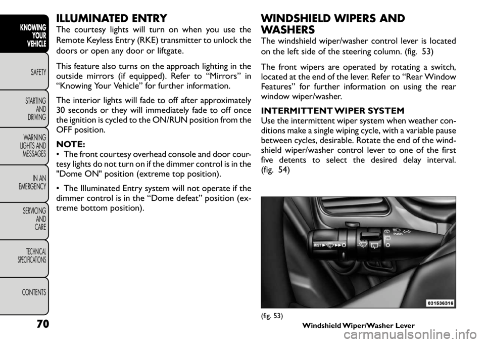
The windshield wiper/washer control lever is located
on the left side of the steering column. (fig. 53)
The front wipers are operated by rotating a switch,
located at the end of the lever. Refer to “Rear Window
Features” for further information on using the rear
window wiper/washer.
INTERMITTENT WIPER SYSTEM
Use the intermittent wiper system when weather con-
ditions make a single wiping cycle, with a variable pause
between cycles, desirable. Rotate the end of the wind-
shield wiper/washer control lever to one of the first
five detents to select the desired delay interval.
(fig. 54)
(fig. 53)
Windshield Wiper/Washer Lever
70
KNOWING
YOUR
VEHICLE
SAFETY
STARTING AND
DRIVING
WARNING
LIGHTS AND
MESSAGES
IN AN
EMERGENCY
SERVICING AND
CARETECHNICAL
SPECIFICATIONSCONTENTS
Page 80 of 267
HEADLIGHT WASHERS — IF EQUIPPED
The Headlight Washers are recessed into the top of
the fascia, centrally located below each headlight.
The windshield wiper/washer control lever operates
the headlight washers when the ignition switch is in the
ON position and the headlights are ON. The lever is
located on the left side of the steering column.
To use the headlight washers, push the washer knob,
located on the end of the multifunction lever, inward to
the second detent to activate the windshield washers
and release it. When this is done, the two stationary
washer nozzles at each headlight spray one timed
high-pressure spray of washer fluid onto each headlight
lens. In addition, the windshield washers will spray the
windshield and the windshield wipers will cycle.
NOTE:After turning the ignition switch and head-
lights ON, the headlight washers will operate on the
first spray of the windshield washer and then every
eleventh spray after that. REAR WINDOW FEATURES
REAR WINDOW WIPER/WASHER
The rear window wiper/washer control is located on
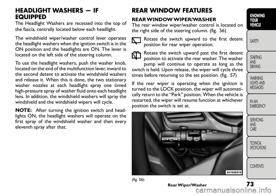
the right side of the steering column. (fig. 56)
Rotate the switch upward to the first detent
position for rear wiper operation.
Rotate the switch upward past the first detent
position to activate the rear washer. The washer
pump will continue to operate as long as the
switch is held. Upon release, the wiper will cycle three
times before returning to the set position. (fig. 57)
If the rear wiper is operating when the ignition is
turned to the LOCK position, the wiper will automati-
cally return to the “Park” position. When the vehicle is
restarted, the wiper will resume function at whichever
position the switch is set at.
(fig. 56) Rear Wiper/Washer
73KNOWING
YOURVEHICLESAFETY
STARTING ANDDRIVING
WARNING
LIGHTS AND
MESSAGES
IN AN
EMERGENCY
SERVICING AND
CARETECHNICAL
SPECIFICATIONSCONTENTS
Page 82 of 267
ELECTRONIC SPEED CONTROL — IF EQUIPPED
When engaged, the Electronic Speed Control takes
over accelerator operations at speeds greater than
40 km/h.
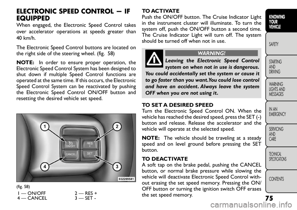
The Electronic Speed Control buttons are located on
the right side of the steering wheel. (fig. 58)
NOTE:In order to ensure proper operation, the
Electronic Speed Control System has been designed to
shut down if multiple Speed Control functions are
operated at the same time. If this occurs, the Electronic
Speed Control System can be reactivated by pushing
the Electronic Speed Control ON/OFF button and
resetting the desired vehicle set speed. TO ACTIVATE
Push the ON/OFF button. The Cruise Indicator Light
in the instrument cluster will illuminate. To turn the
system off, push the ON/OFF button a second time.
The Cruise Indicator Light will turn off. The system
should be turned off when not in use.
WARNING!
Leaving the Electronic Speed Control
system on when not in use is dangerous.
You could accidentally set the system or cause it
to go faster than you want .You could lose control
and have an accident . Always leave the system
OFF when you are not using it .
TO SET A DESIRED SPEED
Turn the Electronic Speed Control ON. When the
vehicle has reached the desired speed, press the SET (-)
button and release. Release the accelerator and the
vehicle will operate at the selected speed.
NOTE: The vehicle should be traveling at a steady
speed and on level ground before pressing the SET
button.
TO DEACTIVATE
A soft tap on the brake pedal, pushing the CANCEL
button, or normal brake pressure while slowing the
vehicle will deactivate Electronic Speed Control with-
out erasing the set speed memory. Pressing the ON/
OFF button or turning the ignition switch OFF erases
the set speed memory.
(fig. 58)
1 — ON/OFF 2 — RES +
4 — CANCEL 3 — SET - 75
KNOWING
YOURVEHICLESAFETY
STARTING ANDDRIVING
WARNING
LIGHTS AND
MESSAGES
IN AN
EMERGENCY
SERVICING AND
CARETECHNICAL
SPECIFICATIONSCONTENTS
Page 114 of 267
• The ABS motor running (it may continue to run for ashort time after the stop),
• The clicking sound of solenoid valves,
• Brake pedal pulsations, and
• A slight drop or fall away of the brake pedal at the end of the stop.
These are all normal characteristics of ABS.
WARNING!
The ABS contains sophisticated elec-
tronic equipment that may be suscep-
tible to interference caused by improperly in-
stalled or high output radio transmitting
equipment . This interference can cause possible
loss of anti-lock braking capability. Installation
of such equipment should be performed by quali-
fied professionals.
Pumping of the Anti-Lock Brakes will diminish
their effectiveness and may lead to an accident .
Pumping makes the stopping distance longer. Just
press firmly on your brake pedal when you need
to slow down or stop.
The ABS cannot prevent the natural laws of
physics from acting on the vehicle, nor can it
increase braking or steering efficiency beyond
that afforded by the condition of the vehicle
brakes and tires or the traction afforded.
(Continued)(Continued)
The ABS cannot prevent accidents, including
those resulting from excessive speed in turns,
following another vehicle too closely, or hydro-
planing.
The capabilities of an ABS equipped vehicle
must never be exploited in a reckless or danger-
ous manner, which could jeopardize the user's
safety or the safety of others.
All vehicle wheels and tires must be the same size and
type and tires must be properly inflated to produce
accurate signals for the computer.
Anti-Lock Brake Light The Anti-Lock Brake Light monitors the ABS.
The light will turn on when the ignition
switch is turned to the ON position and may
stay on for as long as four seconds.
If the ABS Light remains on or comes on while driving,
it indicates that the Anti-Lock portion of the brake
system is not functioning and that service is required.
However, the conventional brake system will continue
to operate normally if the Brake System Warning Light
is not on.
If the ABS Light is on, the brake system should be
serviced as soon as possible to restore the benefits of
Anti-Lock brakes. If the ABS Light does not come on
when the ignition switch is turned to the ON position,
have the light repaired as soon as possible.
107KNOWING
YOURVEHICLESAFETY
STARTING ANDDRIVING
WARNING
LIGHTS AND
MESSAGES
IN AN
EMERGENCY
SERVICING AND
CARETECHNICAL
SPECIFICATIONSCONTENTS