display FIAT FREEMONT 2012 Owner handbook (in English)
[x] Cancel search | Manufacturer: FIAT, Model Year: 2012, Model line: FREEMONT, Model: FIAT FREEMONT 2012Pages: 332, PDF Size: 5.61 MB
Page 48 of 332
HEATED SEATS (for versions/markets, where
provided)
On some models, the front driver and passenger seats
may be equipped with heaters in both the seat cushions
and seatbacks. The heated seats are operated using the
Uconnect Touch™ System.
For Vehicles Equipped With Uconnect Touch™ 4.3:
Touch the CLIMATE hard-key (located on the left side
of the Uconnect Touch™ display) to enter the climate
control screen.Touch the “Driver” or “Pass” seat soft-key
(located on the Uconnect Touch™ display)
once to select HI-level heating. Touch the
soft-key a second time to select LO-level heating. Touch the soft-key a third time to shut the
heating elements OFF.
For Vehicles Equipped With Uconnect Touch™
8.4 And 8.4 Nav:
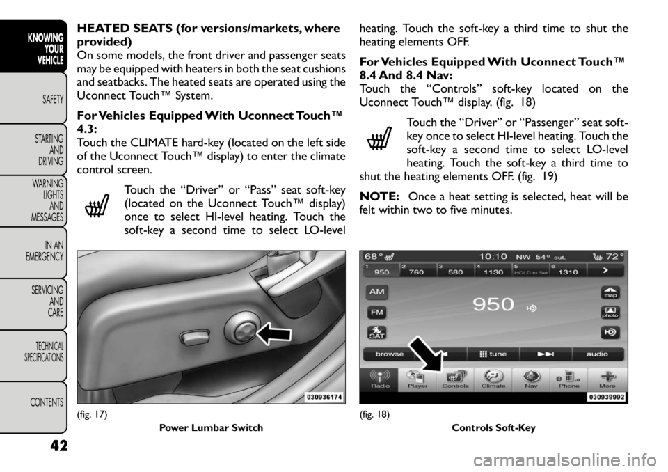
Touch the “Controls” soft-key located on the
Uconnect Touch™ display. (fig. 18)
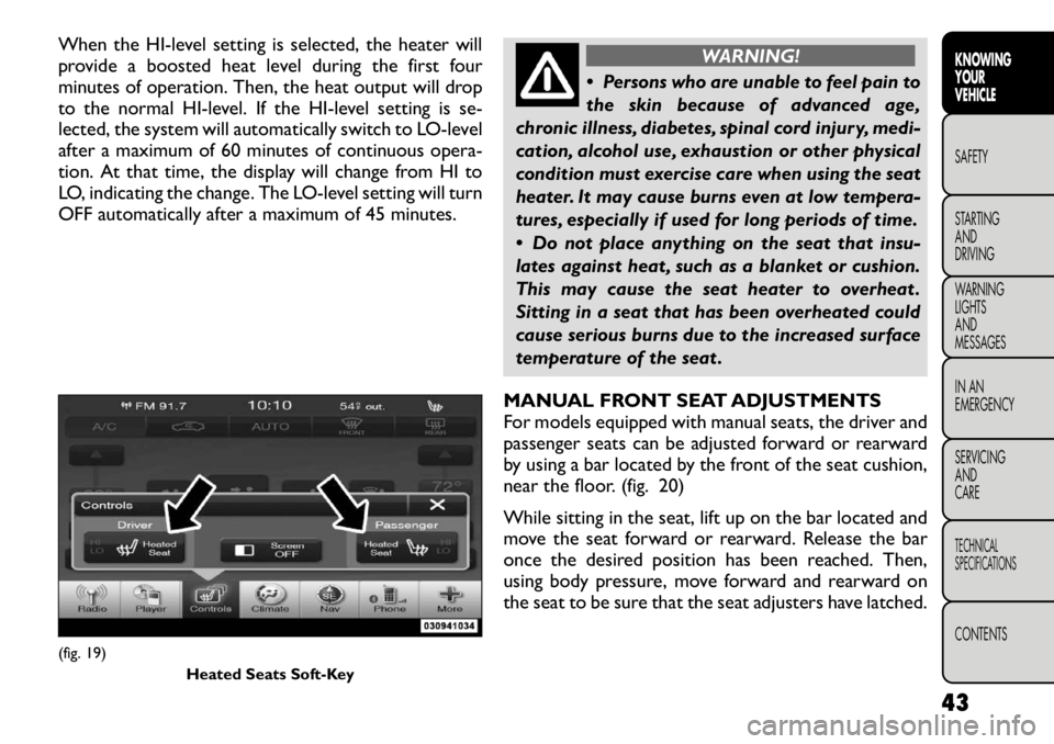
Touch the “Driver” or “Passenger” seat soft-
key once to select HI-level heating. Touch the
soft-key a second time to select LO-level
heating. Touch the soft-key a third time to
shut the heating elements OFF. (fig. 19)
NOTE: Once a heat setting is selected, heat will be
felt within two to five minutes.(fig. 17)
Power Lumbar Switch
(fig. 18) Controls Soft-Key
42
KNOWINGYOUR
VEHICLE
SAFETY
STARTING AND
DRIVING
WARNING LIGHTSAND
MESSAGES
IN AN
EMERGENCY
SERVICING AND
CARETECHNICAL
SPECIFICATIONSCONTENTS
Page 49 of 332
When the HI-level setting is selected, the heater will
provide a boosted heat level during the first four
minutes of operation. Then, the heat output will drop
to the normal HI-level. If the HI-level setting is se-
lected, the system will automatically switch to LO-level
after a maximum of 60 minutes of continuous opera-
tion. At that time, the display will change from HI to
LO, indicating the change. The LO-level setting will turn
OFF automatically after a maximum of 45 minutes.
WARNING!
Persons who are unable to feel pain to
the skin because of advanced age,
chronic illness, diabetes, spinal cord injury, medi-
cation, alcohol use, exhaustion or other physical
condition must exercise care when using the seat
heater. It may cause burns even at low tempera-
tures, especially if used for long periods of time.
Do not place anything on the seat that insu-
lates against heat , such as a blanket or cushion.
This may cause the seat heater to overheat .
Sitting in a seat that has been overheated could
cause serious burns due to the increased surface
temperature of the seat .
MANUAL FRONT SEAT ADJUSTMENTS
For models equipped with manual seats, the driver and
passenger seats can be adjusted forward or rearward
by using a bar located by the front of the seat cushion,
near the floor. (fig. 20)
While sitting in the seat, lift up on the bar located and
move the seat forward or rearward. Release the bar
once the desired position has been reached. Then,
using body pressure, move forward and rearward on
the seat to be sure that the seat adjusters have latched.
(fig. 19) Heated Seats Soft-Key
43
KNOWING
YOURVEHICLESAFETY
STARTING ANDDRIVING
WARNING LIGHTSAND
MESSAGES
IN AN
EMERGENCY
SERVICING AND
CARETECHNICAL
SPECIFICATIONSCONTENTS
Page 65 of 332
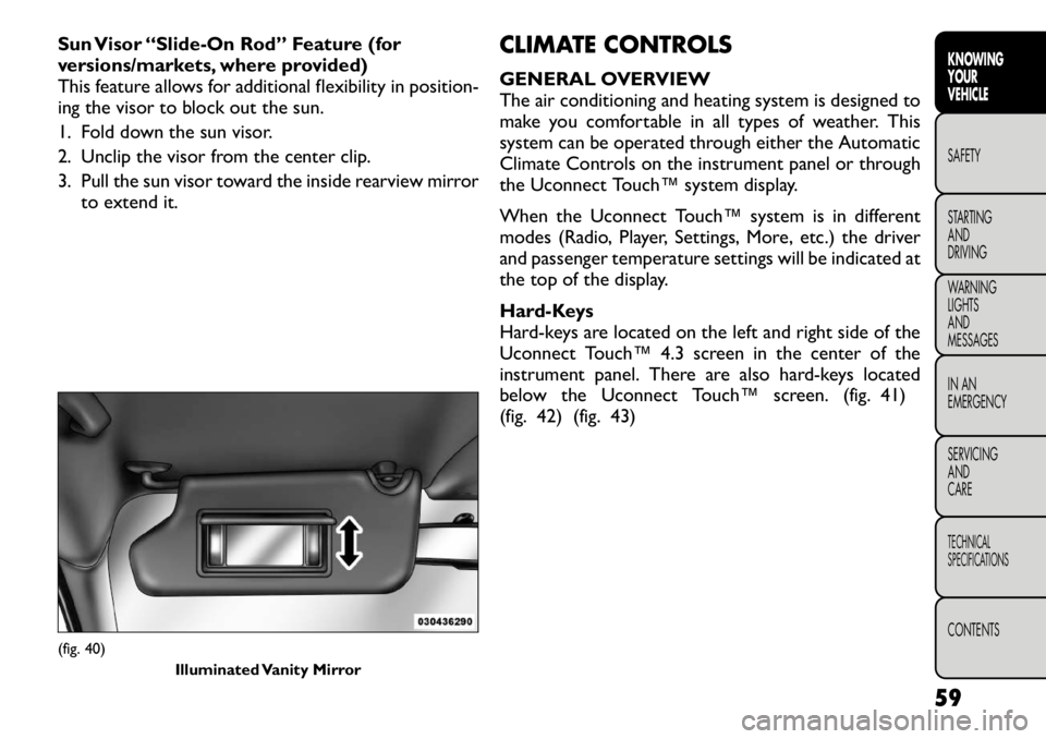
Sun Visor “Slide-On Rod” Feature (for
versions/markets, where provided)
This feature allows for additional flexibility in position-
ing the visor to block out the sun.
1. Fold down the sun visor.
2. Unclip the visor from the center clip.
3. Pull the sun visor toward the inside rearview mirrorto extend it. CLIMATE CONTROLS
GENERAL OVERVIEW
The air conditioning and heating system is designed to
make you comfortable in all types of weather. This
system can be operated through either the Automatic
Climate Controls on the instrument panel or through
the Uconnect Touch™ system display.
When the Uconnect Touch™ system is in different
modes (Radio, Player, Settings, More, etc.) the driver
and passenger temperature settings will be indicated at
the top of the display.
Hard-Keys
Hard-keys are located on the left and right side of the
Uconnect Touch™ 4.3 screen in the center of the
instrument panel. There are also hard-keys located
below the Uconnect Touch™ screen. (fig. 41)
(fig. 42) (fig. 43)(fig. 40)
Illuminated Vanity Mirror
59
KNOWING
YOURVEHICLESAFETY
STARTING ANDDRIVING
WARNING LIGHTSAND
MESSAGES
IN AN
EMERGENCY
SERVICING AND
CARETECHNICAL
SPECIFICATIONSCONTENTS
Page 71 of 332

NOTE:In cold weather, use of Recirculation mode
may lead to excessive window fogging. The Recircula-
tion mode is not allowed in Mix, Floor and Defrost
modes to improve window clearing operation. Recir-
culation will be disabled automatically if these modes
are selected. Attempting to use Recirculation while in
these modes will cause the LED in the control button
to blink and then turn off.
AUTOMATIC TEMPERATURE CONTROL
(ATC)
ATC Hard-keys are located in the center of the instru-
ment panel.
Soft-keys are accessible on the Uconnect Touch™
system screen.
Automatic Operation
1. Press the AUTO hard-key or soft-key button (9) on the Automatic Temperature Control (ATC) Panel.
2. Next, adjust the temperature you would like the system to maintain by adjusting the driver and pas-
senger temperature hard or soft control buttons (6,
7, 10, 11). Once the desired temperature is dis-
played, the system will achieve and automatically
maintain that comfort level.
3. When the system is set up for your comfort level, it is not necessary to change the settings. You will
experience the greatest efficiency by simply allowing
the system to function automatically. NOTE:
• It is not necessary to move the temperature settings
for cold or hot vehicles. The system automatically
adjusts the temperature, mode and blower speed to
provide comfort as quickly as possible.
• The temperature can be displayed in U.S. or Metric
units by selecting the US/M customer-programmable
feature. Refer to the “Uconnect Touch™ System Set-
tings” in this section of the manual.
To provide you with maximum comfort in the Auto-
matic mode, during cold start-ups the blower fan will
remain on low until the engine warms up. The blower
will increase in speed and transition into Auto mode.
Manual Operation
The system allows for manual selection of blower
speed, air distribution mode, A/C status and recircula-
tion control.
The blower fan speed can be set to any fixed speed by
adjusting the blower control. The fan will now operate
at a fixed speed until additional speeds are selected.
This allows the front occupants to control the volume
of air circulated in the vehicle and cancel the Auto
mode.
The operator can also select the direction of the
airflow by selecting one of the available mode settings.
A/C operation and Recirculation control can also be
manually selected in Manual operation.
65
KNOWING
YOURVEHICLESAFETY
STARTING ANDDRIVING
WARNING LIGHTSAND
MESSAGES
IN AN
EMERGENCY
SERVICING AND
CARETECHNICAL
SPECIFICATIONSCONTENTS
Page 72 of 332
REAR AUTOMATIC TEMPERATURE
CONTROL (ATC) (for versions/markets,
where provided)
The rear ATC system has floor air outlets at the rear
right side of the 3rd Row seats and overhead outlets at
each outboard rear seating position. The system pro-
vides heated air through the floor outlets or cool,
dehumidified air through the headliner outlets.
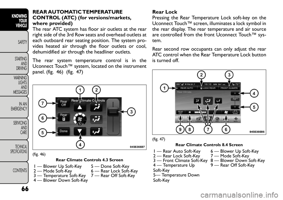
The rear system temperature control is in the
Uconnect Touch™ system, located on the instrument
panel. (fig. 46) (fig. 47)Rear Lock
Pressing the Rear Temperature Lock soft-key on the
Uconnect Touch™ screen, illuminates a lock symbol in
the rear display. The rear temperature and air source
are controlled from the front Uconnect Touch™ sys-
tem.
Rear second row occupants can only adjust the rear
ATC control when the Rear Temperature Lock button
is turned off.(fig. 46)
Rear Climate Controls 4.3 Screen
1 — Blower Up Soft-Key 5 — Done Soft-Key
2 — Mode Soft-Key 6 — Rear Lock Soft-Key
3 — Temperature Soft-Key 7 — Rear Off Soft-Key
4 — Blower Down Soft-Key
(fig. 47) Rear Climate Controls 8.4 Screen
1 — Rear Auto Soft-Key 6 — Blower Up Soft-Key
2 — Rear Lock Soft-Key 7 — Mode Soft-Key
3 — Front Climate Soft-Key 8 — Blower Down Soft-Key
4 — Temperature Up
Soft-Key 9 — Rear Off Soft-Key
5— Temperature Down
Soft-Key
66
KNOWING YOUR
VEHICLE
SAFETY
STARTING AND
DRIVING
WARNING LIGHTSAND
MESSAGES
IN AN
EMERGENCY
SERVICING AND
CARETECHNICAL
SPECIFICATIONSCONTENTS
Page 73 of 332
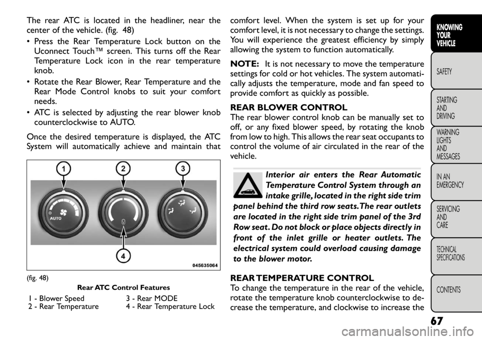
The rear ATC is located in the headliner, near the
center of the vehicle. (fig. 48)
• Press the Rear Temperature Lock button on theUconnect Touch™ screen. This turns off the Rear
Temperature Lock icon in the rear temperature
knob.
• Rotate the Rear Blower, Rear Temperature and the Rear Mode Control knobs to suit your comfortneeds.
• ATC is selected by adjusting the rear blower knob counterclockwise to AUTO.
Once the desired temperature is displayed, the ATC
System will automatically achieve and maintain that comfort level. When the system is set up for your
comfort level, it is not necessary to change the settings.
You will experience the greatest efficiency by simply
allowing the system to function automatically.
NOTE:
It is not necessary to move the temperature
settings for cold or hot vehicles. The system automati-
cally adjusts the temperature, mode and fan speed to
provide comfort as quickly as possible.
REAR BLOWER CONTROL
The rear blower control knob can be manually set to
off, or any fixed blower speed, by rotating the knob
from low to high. This allows the rear seat occupants to
control the volume of air circulated in the rear of the
vehicle.
Interior air enters the Rear Automatic
Temperature Control System through an
intake grille, located in the right side trim
panel behind the third row seats.The rear outlets
are located in the right side trim panel of the 3rd
Row seat . Do not block or place objects directly in
front of the inlet grille or heater outlets. The
electrical system could overload causing damage
to the blower motor.
REAR TEMPERATURE CONTROL
To change the temperature in the rear of the vehicle,
rotate the temperature knob counterclockwise to de-
crease the temperature, and clockwise to increase the
(fig. 48) Rear ATC Control Features
1 - Blower Speed 3 - Rear MODE
2 - Rear Temperature 4 - Rear Temperature Lock
67
KNOWING
YOURVEHICLESAFETY
STARTING ANDDRIVING
WARNING LIGHTSAND
MESSAGES
IN AN
EMERGENCY
SERVICING AND
CARETECHNICAL
SPECIFICATIONSCONTENTS
Page 80 of 332
DIMMER CONTROLS
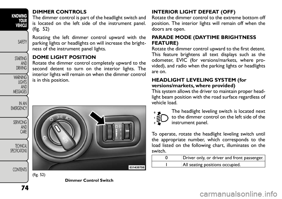
The dimmer control is part of the headlight switch and
is located on the left side of the instrument panel.
(fig. 52)
Rotating the left dimmer control upward with the
parking lights or headlights on will increase the bright-
ness of the instrument panel lights.
DOME LIGHT POSITION
Rotate the dimmer control completely upward to the
second detent to turn on the interior lights. The
interior lights will remain on when the dimmer control
is in this position.INTERIOR LIGHT DEFEAT (OFF)
Rotate the dimmer control to the extreme bottom off
position. The interior lights will remain off when the
doors are open.
PARADE MODE (DAYTIME BRIGHTNESS
FEATURE)
Rotate the dimmer control upward to the first detent.
This feature brightens all text displays such as the
odometer, EVIC (for versions/markets, where pro-
vided), and radio when the parking lights or headlights
are on.
HEADLIGHT LEVELING SYSTEM (for
versions/markets, where provided)
This system allows the driver to maintain proper head-
light beam position with the road surface regardless of
vehicle load.
The headlight leveling switch is located next
to the dimmer control on the left side of the
instrument panel.
To operate, rotate the headlight leveling switch until
the appropriate number, which corresponds to the
load listed on the following chart, illuminates on the
switch.
0 Driver only, or driver and front passenger.
1 All seating positions occupied.
(fig. 52) Dimmer Control Switch
74
KNOWINGYOUR
VEHICLE
SAFETY
STARTING AND
DRIVING
WARNING LIGHTSAND
MESSAGES
IN AN
EMERGENCY
SERVICING AND
CARETECHNICAL
SPECIFICATIONSCONTENTS
Page 127 of 332
LOOSE FUEL FILLER CAP MESSAGE
If the vehicle diagnostic system determines that the
fuel filler cap is loose, improperly installed, or damaged,
the word “gASCAP” will display in the odometer. If this
occurs, tighten the fuel filler cap until a “clicking” sound
is heard and press the TRIP ODOMETER button to
turn off the message. If the problem persists, the
message will appear the next time the vehicle is
started.
A loose, improperly installed, or damaged fuel filler cap
may also turn on the MIL.POWER STEERING
The standard power steering system will give you good
vehicle response and increased ease of maneuverability
in tight spaces. The system will provide mechanical
steering capability if power assist is lost.
If for some reason the power assist is interrupted, it
will still be possible to steer your vehicle. Under these
conditions, you will observe a substantial increase in
steering effort, especially at very low vehicle speeds
and during parking maneuvers.
NOTE:
• Increased noise levels at the end of the steering
wheel travel are considered normal and do not indicate
that there is a problem with the power steering system.
• Upon initial start-up in cold weather, the power
steering pump may make noise for a short amount of
time. This is due to the cold, thick fluid in the steering
system. This noise should be considered normal, and it
does not in any way damage the steering system.
WARNING!
Continued operation with reduced
power steering assist could pose a safety
risk to yourself and others. Service should be
obtained as soon as possible.
121
KNOWING
YOURVEHICLESAFETY
STARTING ANDDRIVING
WARNING LIGHTSAND
MESSAGES
IN AN
EMERGENCY
SERVICING AND
CARETECHNICAL
SPECIFICATIONSCONTENTS
Page 132 of 332
PREMIUM SYSTEM (for versions/markets,
where provided)
The Tire Pressure Monitor System (TPMS) uses wire-
less technology with wheel rim mounted electronic
sensors to monitor tire pressure levels. Sensors,
mounted to each wheel as part of the valve stem,
transmit tire pressure readings to the receiver module.
NOTE:It is particularly important for you to check
the tire pressure in all of the tires on your vehicle
monthly and to maintain the proper pressure.
The TPMS consists of the following components:
• Receiver module
• Four Tire Pressure Monitoring Sensors
• Three Trigger modules (mounted in three of the four wheel-wells)
• Various Tire Pressure Monitoring System messages, which display in the Electronic Vehicle Information
Center (EVIC)
• Tire Pressure Monitoring Telltale Light
Tire Pressure Monitoring Low Pressure
Warnings
The Tire Pressure Monitoring Telltale Light will
illuminate in the instrument cluster and a chime
will sound when tire pressure is low in one or
more of the four active road tires. In addition, the
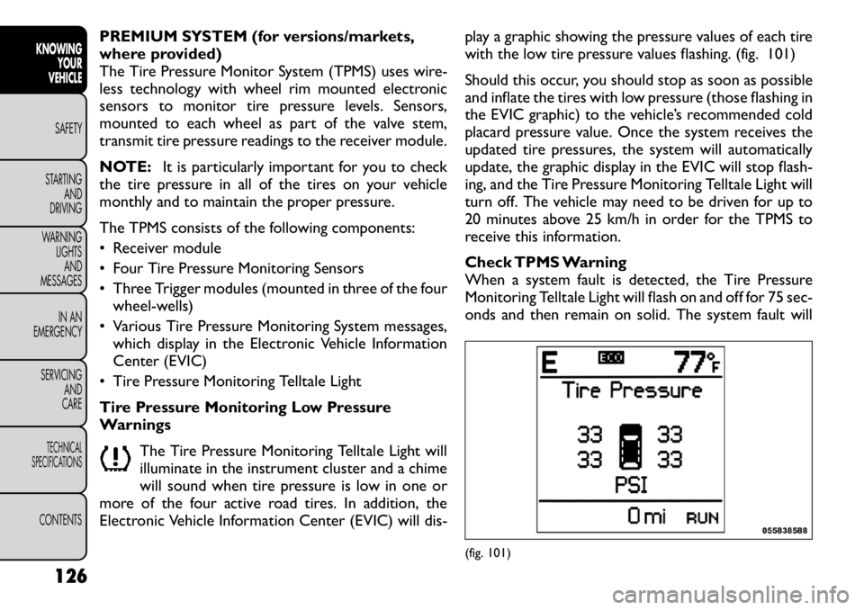
Electronic Vehicle Information Center (EVIC) will dis- play a graphic showing the pressure values of each tire
with the low tire pressure values flashing. (fig. 101)
Should this occur, you should stop as soon as possible
and inflate the tires with low pressure (those flashing in
the EVIC graphic) to the vehicle’s recommended cold
placard pressure value. Once the system receives the
updated tire pressures, the system will automatically
update, the graphic display in the EVIC will stop flash-
ing, and the Tire Pressure Monitoring Telltale Light will
turn off. The vehicle may need to be driven for up to
20 minutes above 25 km/h in order for the TPMS to
receive this information.
Check TPMS Warning
When a system fault is detected, the Tire Pressure
Monitoring Telltale Light will flash on and off for 75 sec-
onds and then remain on solid. The system fault will
(fig. 101)
126
KNOWING YOUR
VEHICLE
SAFETY
STARTING AND
DRIVING
WARNING LIGHTSAND
MESSAGES
IN AN
EMERGENCY
SERVICING AND
CARETECHNICAL
SPECIFICATIONSCONTENTS
Page 133 of 332
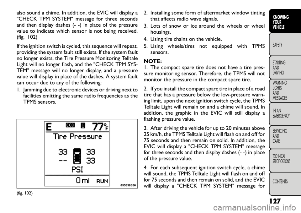
also sound a chime. In addition, the EVIC will display a
"CHECK TPM SYSTEM" message for three seconds
and then display dashes (- -) in place of the pressure
value to indicate which sensor is not being received.
(fig. 102)
If the ignition switch is cycled, this sequence will repeat,
providing the system fault still exists. If the system fault
no longer exists, the Tire Pressure Monitoring Telltale
Light will no longer flash, and the "CHECK TPM SYS-
TEM" message will no longer display, and a pressure
value will display in place of the dashes. A system fault
can occur due to any of the following:
1. Jamming due to electronic devices or driving next tofacilities emitting the same radio frequencies as the
TPMS sensors. 2. Installing some form of aftermarket window tinting
that affects radio wave signals.
3. Lots of snow or ice around the wheels or wheel housings.
4. Using tire chains on the vehicle.
5. Using wheels/tires not equipped with TPMS sensors.
NOTE:
1. The compact spare tire does not have a tire pres-
sure monitoring sensor. Therefore, the TPMS will not
monitor the pressure in the compact spare tire.
2. If you install the compact spare tire in place of a road
tire that has a pressure below the low-pressure warn-
ing limit, upon the next ignition switch cycle, the TPMS
Telltale Light will remain on and a chime will sound. In
addition, the graphic in the EVIC will still display a
flashing pressure value.
3. After driving the vehicle for up to 20 minutes above
25 km/h, the TPMS Telltale Light will flash on and off for
75 seconds and then remain on solid. In addition, the
EVIC will display a "CHECK TPM SYSTEM" message
for three seconds and then display dashes (- -) in place
of the pressure value.
4. For each subsequent ignition switch cycle, a chime
will sound, the TPMS Telltale Light will flash on and off
for 75 seconds and then remain on solid, and the EVIC
will display a "CHECK TPM SYSTEM" message for(fig. 102) 127
KNOWING
YOURVEHICLESAFETY
STARTING ANDDRIVING
WARNING LIGHTSAND
MESSAGES
IN AN
EMERGENCY
SERVICING AND
CARETECHNICAL
SPECIFICATIONSCONTENTS