interior lights FIAT FREEMONT 2012 Owner handbook (in English)
[x] Cancel search | Manufacturer: FIAT, Model Year: 2012, Model line: FREEMONT, Model: FIAT FREEMONT 2012Pages: 332, PDF Size: 5.61 MB
Page 188 of 332

The Advanced Front Air Bags have a multistage inflator
design. This allows the air bag to have different rates of
inflation based on the severity and type of collision.
This vehicle may be equipped with a driver and/or front
passenger seat belt buckle switch that detects whether
the driver or front passenger seat belt is fastened. The
seat belt buckle switch may adjust the inflation rate of
the Advanced Front Air Bags.
This vehicle is equipped with Supplemental Side Air Bag
Inflatable Curtains (SABIC) to protect the driver, front,
and rear passengers sitting next to a window. The
SABIC air bags are located above the side windows and
their covers are also labeled: SRS AIRBAG.
This vehicle is equipped with Supplemental Seat-
Mounted Side Air Bags (SAB). The SABs are marked
with an air bag label sewn into the outboard side of the
front seats.
NOTE:
• Air Bag covers may not be obvious in the interior
trim, but they will open during air bag deployment.
• After any accident, the vehicle should be taken to an
authorized dealer immediately.
Air Bag System Components
Your vehicle may be equipped with the following air bag
system components:
• Occupant Restraint Controller (ORC)
• Air Bag Warning Light• Steering Wheel and Column
• Instrument Panel
• Knee Impact Bolster (for versions/markets, where
provided)
• Driver Advanced Front Air Bag
• Passenger Advanced Front Air Bag
• Supplemental Seat-Mounted Side Air Bags (SAB)
• Supplemental Side Air Bag Inflatable Curtains (SABIC)
• Front and Side Impact Sensors
• Front Seat Belt Pretensioners, Seat Belt Buckle Switch
ADVANCED FRONT AIR BAG FEATURES
The Advanced Front Air Bag system has multistage
driver and front passenger air bags. This system pro-
vides output appropriate to the severity and type of
collision as determined by the Occupant Restraint
Controller (ORC), which may receive information
from the front impact sensors.
The first stage inflator is triggered immediately during
an impact that requires air bag deployment. This low
output is used in less severe collisions. A higher energy
output is used for more severe collisions.
182
KNOWING YOUR
VEHICLESAFETYSTARTING AND
DRIVING
WARNING LIGHTSAND
MESSAGES
IN AN
EMERGENCY
SERVICING AND
CARETECHNICAL
SPECIFICATIONSCONTENTS
Page 190 of 332
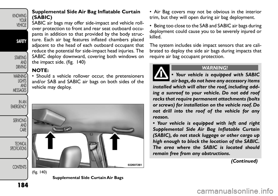
Supplemental Side Air Bag Inflatable Curtain (SABIC)
SABIC air bags may offer side-impact and vehicle roll-
over protection to front and rear seat outboard occu-
pants in addition to that provided by the body struc-
ture. Each air bag features inflated chambers placed
adjacent to the head of each outboard occupant that
reduce the potential for side-impact head injuries. The
SABIC deploy downward, covering both windows on
the impact side. (fig. 140)
NOTE:
• Should a vehicle rollover occur, the pretensioners
and/or SAB and SABIC air bags on both sides of the
vehicle may deploy.• Air Bag covers may not be obvious in the interior
trim, but they will open during air bag deployment.
• Being too close to the SAB and SABIC air bags during
deployment could cause you to be severely injured orkilled.
The system includes side impact sensors that are cali-
brated to deploy the side air bags during impacts that
require air bag occupant protection.
WARNING!
Your vehicle is equipped with SABIC
air bags, do not have any accessory items
installed which will alter the roof, including add-
ing a sunroof to your vehicle. Do not add roof
racks that require permanent attachments (bolts
or screws) for installation on the vehicle roof. Do
not drill into the roof of the vehicle for any
reason.
Your vehicle is equipped with left and right
Supplemental Side Air Bag Inflatable Curtain
(SABIC), do not stack luggage or other cargo up
high enough to block the location of the SABIC.
The area where the SABIC is located should
remain free from any obstructions.
(Continued)
(fig. 140)Supplemental Side Curtain Air Bags
184
KNOWING YOUR
VEHICLESAFETYSTARTING AND
DRIVING
WARNING LIGHTSAND
MESSAGES
IN AN
EMERGENCY
SERVICING AND
CARETECHNICAL
SPECIFICATIONSCONTENTS
Page 195 of 332
• Cut off fuel to the engine.
• Flash hazard lights as long as the battery has poweror until the ignition is cycled off.
• Turn on the interior lights, which remain on as long as the battery has power or until the ignition key is
removed.
• Unlock the doors automatically.
If A Deployment Occurs
The Advanced Front Air Bags are designed to deflate
immediately after deployment.
NOTE: Front and/or side air bags will not deploy in all
collisions. This does not mean something is wrong with
the air bag system.
If you do have a collision which deploys the air bags, any
or all of the following may occur:
• The nylon air bag material may sometimes cause abrasions and/or skin reddening to the driver and
front passenger as the air bags deploy and unfold.
The abrasions are similar to friction rope burns or
those you might get sliding along a carpet or gymna-
sium floor. They are not caused by contact with
chemicals. They are not permanent and normally
heal quickly. However, if you haven't healed signifi-
cantly within a few days, or if you have any blistering,
see your doctor immediately. • As the air bags deflate, you may see some smoke-like
particles. The particles are a normal by-product of
the process that generates the non-toxic gas used for
air bag inflation. These airborne particles may irritate
the skin, eyes, nose, or throat. If you have skin or eye
irritation, rinse the area with cool water. For nose or
throat irritation, move to fresh air. If the irritation
continues, see your doctor. If these particles settle
on your clothing, follow the garment manufacturer's
instructions for cleaning.
Do not drive your vehicle after the air bags have
deployed. If you are involved in another collision, the
air bags will not be in place to protect you.
WARNING!
Deployed air bags and seat belt preten-
sioners cannot protect you in another
collision. Have the air bags, seat belt pretension-
ers, and the front seat belt retractor assemblies
replaced by an authorized dealer immediately.
Also, have the Occupant Restraint Controller
(ORC) system serviced as well.
189
KNOWING
YOURVEHICLESAFETYSTARTING ANDDRIVING
WARNING LIGHTSAND
MESSAGES
IN AN
EMERGENCY
SERVICING AND
CARETECHNICAL
SPECIFICATIONSCONTENTS
Page 198 of 332
SAFETY TIPS
TRANSPORTING PASSENGERS
NEVER TRANSPORT PASSENGERS IN THE CARGO
AREA.
WARNING!
Do not leave children or animals inside
parked vehicles in hot weather. Interior
heat build-up may cause serious injury or death.
It is extremely dangerous to ride in a cargo
area, inside or outside of a vehicle. In a collision,
people riding in these areas are more likely to be
seriously injured or killed.
Do not allow people to ride in any area of your
vehicle that is not equipped with seats and seat
belts.
Be sure everyone in your vehicle is in a seat and
using a seat belt properly.
On seven passenger models, do not drive the
vehicle with the second row passenger seat in the
easy entry/exit position (seat cushion flipped up-
ward and seat moved forward), as this position is
only intended for entering and exiting the third
row seats. Failure to follow this warning may
result in personal injury.
(Continued)(Continued)
On seven passenger models, do not allow a
passenger to sit in a third row seat with the
second row seatback(s) folded flat . In a collision,
the passenger could slide underneath the seat
belt and be seriously or even fatally injured.
EXHAUST GAS
WARNING!
Exhaust gases can injure or kill. They
contain carbon monoxide (CO), which is
colorless and odorless. Breathing it can make you
unconscious and can eventually poison you. To
avoid breathing (CO), follow these safety tips:
Do not run the engine in a closed garage or in
confined areas any longer than needed to move
your vehicle in or out of the area.
If you are required to drive with the trunk/
liftgate open, make sure that all windows are
closed and the climate control BLOWER switch is
set at high speed. DO NOT use the recirculation
mode.
If it is necessary to sit in a parked vehicle with
the engine running, adjust your heating or cooling
controls to force outside air into the vehicle. Set
the blower at high speed.
192
KNOWING YOUR
VEHICLESAFETYSTARTING AND
DRIVING
WARNING LIGHTSAND
MESSAGES
IN AN
EMERGENCY
SERVICING AND
CARETECHNICAL
SPECIFICATIONSCONTENTS
Page 202 of 332
(Continued)
Do not leave animals or children inside parked
vehicles in hot weather; interior heat buildup
may cause serious injury or death.
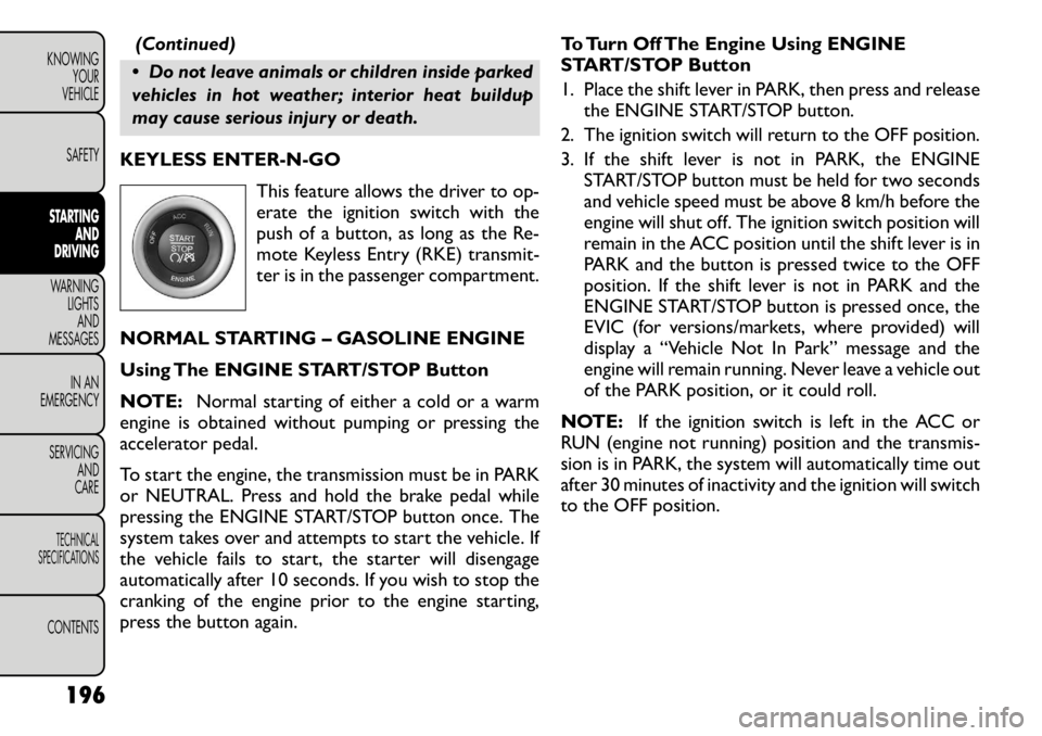
KEYLESS ENTER-N-GO This feature allows the driver to op-
erate the ignition switch with the
push of a button, as long as the Re-
mote Keyless Entry (RKE) transmit-
ter is in the passenger compartment.
NORMAL STARTING – GASOLINE ENGINE
Using The ENGINE START/STOP Button
NOTE: Normal starting of either a cold or a warm
engine is obtained without pumping or pressing the
accelerator pedal.
To start the engine, the transmission must be in PARK
or NEUTRAL. Press and hold the brake pedal while
pressing the ENGINE START/STOP button once. The
system takes over and attempts to start the vehicle. If
the vehicle fails to start, the starter will disengage
automatically after 10 seconds. If you wish to stop the
cranking of the engine prior to the engine starting,
press the button again. To Turn Off The Engine Using ENGINE
START/STOP Button
1. Place the shift lever in PARK, then press and release
the ENGINE START/STOP button.
2. The ignition switch will return to the OFF position.
3. If the shift lever is not in PARK, the ENGINE START/STOP button must be held for two seconds
and vehicle speed must be above 8 km/h before the
engine will shut off. The ignition switch position will
remain in the ACC position until the shift lever is in
PARK and the button is pressed twice to the OFF
position. If the shift lever is not in PARK and the
ENGINE START/STOP button is pressed once, the
EVIC (for versions/markets, where provided) will
display a “Vehicle Not In Park” message and the
engine will remain running. Never leave a vehicle out
of the PARK position, or it could roll.
NOTE: If the ignition switch is left in the ACC or
RUN (engine not running) position and the transmis-
sion is in PARK, the system will automatically time out
after 30 minutes of inactivity and the ignition will switch
to the OFF position.
196
KNOWING YOUR
VEHICLE
SAFETYSTARTING AND
DRIVINGWARNING LIGHTSAND
MESSAGES
IN AN
EMERGENCY
SERVICING AND
CARETECHNICAL
SPECIFICATIONSCONTENTS
Page 252 of 332
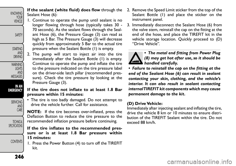
If the sealant (white fluid) does flowthrough the
Sealant Hose (6):
1. Continue to operate the pump until sealant is no longer flowing through hose (typically takes 30 -
70 seconds). As the sealant flows through the Seal-
ant Hose (6), the Pressure Gauge (3) can read as
high as 5 Bar. The Pressure Gauge (3) will decrease
quickly from approximately 5 Bar to the actual tire
pressure when the Sealant Bottle (1) is empty.
2. The pump will start to inject air into the tire immediately after the Sealant Bottle (1) is empty.
Continue to operate the pump and inflate the tire
to the pressure indicated on the tire pressure label
on the driver-side latch pillar (recommended pres-
sure). Check the tire pressure by looking at the
Pressure Gauge (3).
If the tire does not inflate to at least 1.8 Bar
pressure within 15 minutes:
• The tire is too badly damaged. Do not attempt to drive the vehicle further. Call for assistance.
NOTE: If the tire becomes over-inflated, press the
Deflation Button to reduce the tire pressure to the
recommended inflation pressure before continuing.
If the tire inflates to the recommended pres-
sure or is at least 1.8 Bar pressure within
15 minutes:
1. Press the Power Button (4) to turn off the TIREFIT kit. 2. Remove the Speed Limit sticker from the top of the
Sealant Bottle (1) and place the sticker on the
instrument panel.
3. Immediately disconnect the Sealant Hose (6) from the valve stem, reinstall the cap on the fitting at the
end of the hose, and place the TIREFIT kit in the
vehicle storage location. Quickly proceed to (D)
“Drive Vehicle”.
The metal end fitting from Power Plug
(8) may get hot after use, so it should be
handled carefully.
Failure to reinstall the cap on the fitting at the
end of the Sealant Hose (6) can result in sealant
contacting your skin, clothing, and the vehicle’s
interior. It can also result in sealant contacting
internalTIREFIT kit components which may cause
permanent damage to the kit .
(D) Drive Vehicle:
Immediately after injecting sealant and inflating the tire,
drive the vehicle 8 km or 10 minutes to ensure distri-
bution of the TIREFIT Sealant within the tire. Do not
exceed 88 km/h.
246
KNOWING YOUR
VEHICLE
SAFETY
STARTING AND
DRIVING
WARNING LIGHTSAND
MESSAGES
IN AN
EMERGENCY
SERVICING AND
CARETECHNICAL
SPECIFICATIONSCONTENTS
Page 254 of 332

4. Clean any remaining sealant from the TIREFIT hous-ing.
5. Position the new Sealant Bottle (1) in the housing so that the Sealant Hose (6) aligns with the hose slot in
the front of the housing. Press the bottle into the
housing. An audible click will be heard indicating the
bottle is locked into place.
6. Verify that the cap is installed on the fitting at the end of the Sealant Hose (6) and return the hose to
its storage area (located on the bottom of the airpump).
7. Return the TIREFIT kit to its storage location in the vehicle. REPLACEMENT BULBS
All the inside bulbs are brass or glass wedge base.
Aluminum base bulbs are not approved and should not
be used for replacement.
LIGHT BULBS – Interior Bulb Number
Courtesy/Reading Lamps (Incandescent) . . . . . . . . . . 578
Courtesy/Reading Lamps
(Optional LED) . . . . LED (Serviced at Authorized Dealer)
Glove Box Lamp . . . . . . . . . . . . . . . . . . . . . . . . . . 194
Cargo Lamp. . . . . . . . . . . . . . . . . . . . . . . . . . . . . 579
Optional Door Map
Pocket/Cupholder . . LED (Serviced at Authorized Dealer)
NOTE:
For lighted switches, see your authorized
dealer for replacement instructions.
LIGHTS BULBS – Outside Bulb No.
Low Beam Headlamp . . . . . . . . . . . . . . . . . . . . . . . H1
High Beam Headlamp . . . . . . . . . . . . . . . . . . HB3/9005
Front Turn Signal . . . . . . . . . . . . . . . . PY27W/3757AK
Front Position Lamp . . . . . . . . . . . . . . . . . . . . . W5W
Front Fog Lamp . . . . . . . . . . . . . . . . . . . . . . PSX24W
Rear Fog Lamp . . . . . . . . . . . . . . . . . . . . . . . . PS19W
Side Repeater Lamp. . . . . . . . . . . . . . . . . . . . . WY5W
Center High Mounted Stop Lamp (CHMSL) . . . . . . . LED
(Serviced at Authorized Dealer)
Rear Tail/Stop . . . . . LED (Serviced at Authorized Dealer)
Rear Tail Liftgate . . . LED (Serviced at Authorized Dealer)
Rear Turn Signal . . . . . . . . . . . . . . . . . . . . . . WY21W
Backup Lamp . . . . . . . . . . . . . . . . . . . . . . . . . W21W
License Lamp . . . . . . . . . . . . . . . . . . . . . . . . . . . . 168
248
KNOWING YOUR
VEHICLE
SAFETY
STARTING AND
DRIVING
WARNING LIGHTSAND
MESSAGES
IN AN
EMERGENCY
SERVICING AND
CARETECHNICAL
SPECIFICATIONSCONTENTS
Page 260 of 332

FUSES
INTERIOR FUSES
The interior fuse panel is located on the passenger side
under the instrument panel.Cavity
CartridgeFuse
Mini-Fuse Description
F100 30 Amp
Pink 110V AC Inverter –
For Versions/
Markets, Where
Provided
F101 10 Amp
Red Interior Lights
F102 20 Amp
Yellow Cigar Lighter inInstrument
Panel/Left Rear
Power Outlet
F103 20 Amp
Yellow Power Outlet in
Console Bin/Power
Outlet in Rear ofConsole
F105 20 Amp
Yellow Heated Seats – For
Versions/Markets,
Where Provided
F106 20 Amp
Yellow Rear Power Outlet
F107 10 Amp
Red Rear Camera – For
Versions/Markets,
Where Provided
Cavity
Cartridge
Fuse
Mini-Fuse Description
F108 15 Amp
Blue Instrument Panel
F109 10 Amp
Red Climate
Control/HVAC
F110 10 Amp
Red Occupant Restraint
Controller
F112 10 Amp
Red Spare
F114 20 Amp
Yellow Rear HVAC
Blower/Motor
F115 20 Amp
Yellow Rear Wiper Motor
F116 30 Amp
Pink Rear Defroster (EBL)
F117 10 Amp
Red Heated Mirrors
F118 10 Amp
Red Occupant Restraint
Controller
F119 10 Amp
Red Steering Column
Control Module
F120 10 Amp
Red All Wheel Drive –
For Versions/
Markets, Where
Provided
F121 15 Amp
Blue Wireless IgnitionNode
254
KNOWING YOUR
VEHICLE
SAFETY
STARTING AND
DRIVING
WARNING LIGHTSAND
MESSAGES
IN AN
EMERGENCY
SERVICING AND
CARETECHNICAL
SPECIFICATIONSCONTENTS
Page 262 of 332
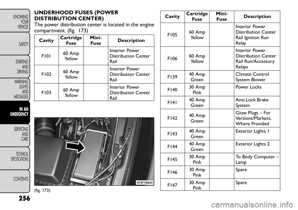
UNDERHOOD FUSES (POWER
DISTRIBUTION CENTER)
The power distribution center is located in the engine
compartment. (fig. 173)Cavity
CartridgeFuse
Mini-Fuse Description
F101 60 Amp
Yellow Interior Power
Distribution CenterRail
F102 60 Amp
Yellow Interior Power
Distribution CenterRail
F103 60 Amp
Yellow Interior Power
Distribution CenterRail
Cavity
Cartridge
Fuse
Mini-Fuse Description
F105 60 Amp
Yellow Interior Power
Distribution Center
Rail Ignition Run
Relay
F106 60 Amp
Yellow Interior Power
Distribution Center
Rail Run/Accessory
Relays
F139 40 Amp
Green Climate Control
System Blower
F140 30 Amp
Pink Power Locks
F141 40 Amp
Green Anti-Lock Brake
System
F142 40 Amp
Green Glow Plugs – For
Versions/Markets,
Where Provided
F143 40 Amp
Green Exterior Lights 1
F144 40 Amp
Green Exterior Lights 2
F145 30 Amp
Pink To Body Computer –Lamp
F146 30 Amp
Pink Spare
F147 30 Amp
Pink Spare
(fig. 173)
256
KNOWING YOUR
VEHICLE
SAFETY
STARTING AND
DRIVING
WARNING LIGHTSAND
MESSAGES
IN AN
EMERGENCY
SERVICING AND
CARETECHNICAL
SPECIFICATIONSCONTENTS
Page 263 of 332
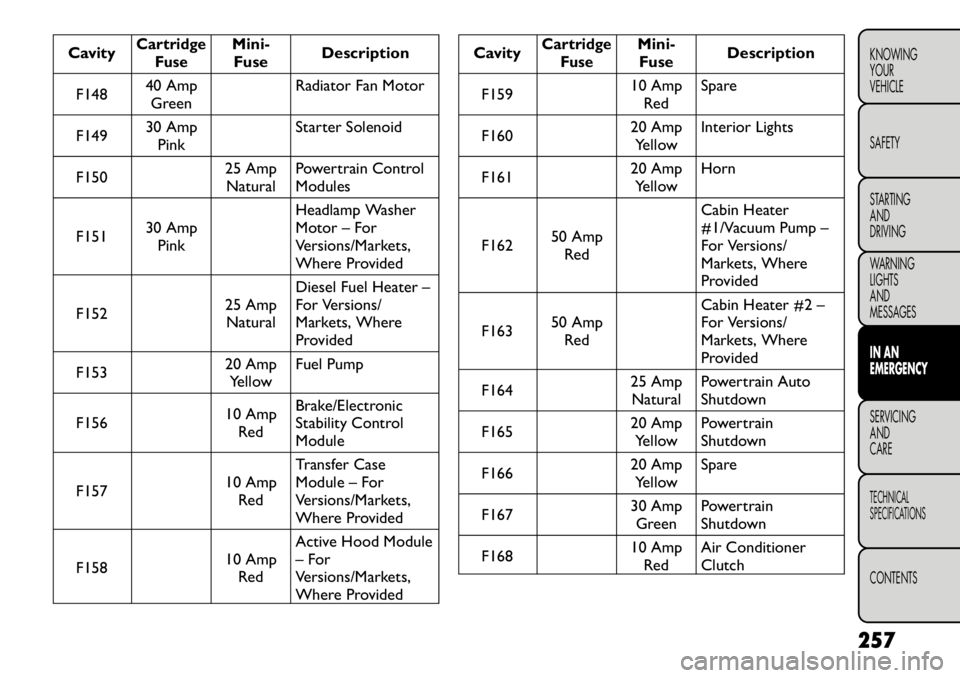
Cavity
CartridgeFuse
Mini-Fuse Description
F148 40 Amp
Green Radiator Fan Motor
F149 30 Amp
Pink Starter Solenoid
F150 25 Amp
Natural Powertrain Control Modules
F151 30 Amp
Pink Headlamp Washer
Motor – For
Versions/Markets,
Where Provided
F152 25 Amp
Natural Diesel Fuel Heater –
For Versions/
Markets, Where
Provided
F153 20 Amp
Yellow Fuel Pump
F156 10 Amp
Red Brake/Electronic
Stability ControlModule
F157 10 Amp
Red Transfer Case
Module – For
Versions/Markets,
Where Provided
F158 10 Amp
Red Active Hood Module
– For
Versions/Markets,
Where Provided
Cavity
Cartridge
Fuse
Mini-Fuse Description
F159 10 Amp
Red Spare
F160 20 Amp
Yellow Interior Lights
F161 20 Amp
Yellow Horn
F162 50 Amp
Red Cabin Heater
#1/Vacuum Pump –
For Versions/
Markets, Where
Provided
F163 50 Amp
Red Cabin Heater #2 –
For Versions/
Markets, Where
Provided
F164 25 Amp
Natural Powertrain Auto
Shutdown
F165 20 Amp
Yellow Powertrain
Shutdown
F166 20 Amp
Yellow Spare
F167 30 Amp
Green Powertrain
Shutdown
F168 10 Amp
Red Air Conditioner
Clutch
257
KNOWING
YOURVEHICLE SAFETY
STARTING ANDDRIVING
WARNING LIGHTSAND
MESSAGESIN AN
EMERGENCYSERVICING AND
CARETECHNICAL
SPECIFICATIONSCONTENTS