lock FIAT FREEMONT 2012 Owner handbook (in English)
[x] Cancel search | Manufacturer: FIAT, Model Year: 2012, Model line: FREEMONT, Model: FIAT FREEMONT 2012Pages: 332, PDF Size: 5.61 MB
Page 58 of 332
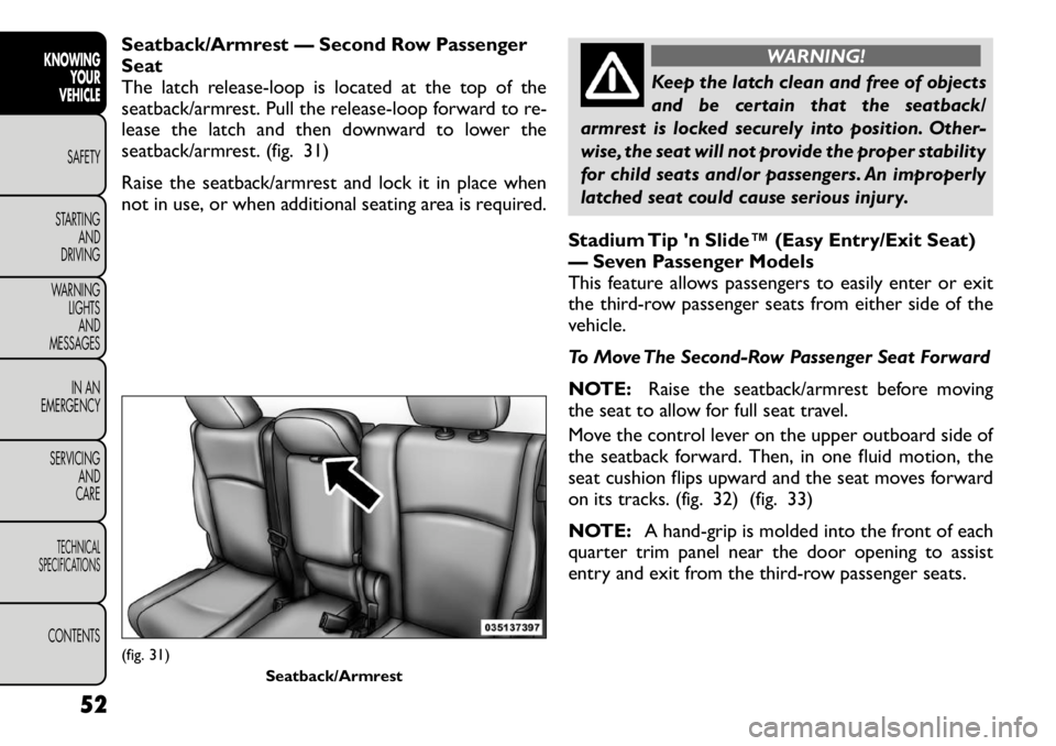
Seatback/Armrest — Second Row Passenger Seat
The latch release-loop is located at the top of the
seatback/armrest. Pull the release-loop forward to re-
lease the latch and then downward to lower the
seatback/armrest. (fig. 31)
Raise the seatback/armrest and lock it in place when
not in use, or when additional seating area is required.
WARNING!
Keep the latch clean and free of objects
and be certain that the seatback/
armrest is locked securely into position. Other-
wise, the seat will not provide the proper stability
for child seats and/or passengers. An improperly
latched seat could cause serious injury.
Stadium Tip 'n Slide™ (Easy Entry/Exit Seat)
— Seven Passenger Models
This feature allows passengers to easily enter or exit
the third-row passenger seats from either side of the
vehicle.
To Move The Second-Row Passenger Seat Forward
NOTE: Raise the seatback/armrest before moving
the seat to allow for full seat travel.
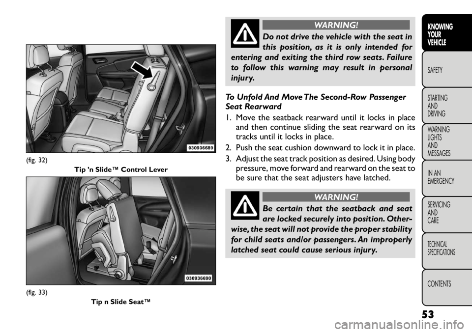
Move the control lever on the upper outboard side of
the seatback forward. Then, in one fluid motion, the
seat cushion flips upward and the seat moves forward
on its tracks. (fig. 32) (fig. 33)
NOTE: A hand-grip is molded into the front of each
quarter trim panel near the door opening to assist
entry and exit from the third-row passenger seats.
(fig. 31)
Seatback/Armrest
52
KNOWING YOUR
VEHICLE
SAFETY
STARTING AND
DRIVING
WARNING LIGHTSAND
MESSAGES
IN AN
EMERGENCY
SERVICING AND
CARETECHNICAL
SPECIFICATIONSCONTENTS
Page 59 of 332
WARNING!
Do not drive the vehicle with the seat in
this position, as it is only intended for
entering and exiting the third row seats. Failure
to follow this warning may result in personal
injury.
To Unfold And Move The Second-Row Passenger
Seat Rearward
1. Move the seatback rearward until it locks in place and then continue sliding the seat rearward on its
tracks until it locks in place.
2. Push the seat cushion downward to lock it in place.
3. Adjust the seat track position as desired. Using body pressure, move forward and rearward on the seat to
be sure that the seat adjusters have latched.
WARNING!
Be certain that the seatback and seat
are locked securely into position. Other-
wise, the seat will not provide the proper stability
for child seats and/or passengers. An improperly
latched seat could cause serious injury.
(fig. 32) Tip 'n Slide™ Control Lever(fig. 33)
Tip n Slide Seat™
53
KNOWING
YOURVEHICLESAFETY
STARTING ANDDRIVING
WARNING LIGHTSAND
MESSAGES
IN AN
EMERGENCY
SERVICING AND
CARETECHNICAL
SPECIFICATIONSCONTENTS
Page 60 of 332
50/50 SPLIT THIRD-ROW PASSENGER
SEATS WITH FOLD-FLAT FEATURE (Seven
Passenger Models)
To provide additional storage area, each third-row
passenger seatback can be folded flat. This allows for
extended cargo space and still maintains some rear
seating room if needed.
NOTE:Prior to folding the third-row passenger seat-
back, make sure the second-row passenger seatback is
not in a reclined position. This will allow the seatback
to fold easily.
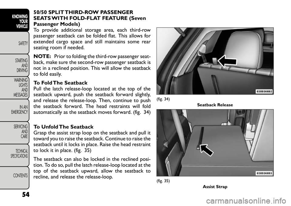
To Fold The Seatback
Pull the latch release-loop located at the top of the
seatback upward, push the seatback forward slightly,
and release the release-loop. Then, continue to push
the seatback forward. The head restraints will fold
automatically as the seatback moves forward. (fig. 34)
To Unfold The Seatback
Grasp the assist strap loop on the seatback and pull it
toward you to raise the seatback. Continue to raise the
seatback until it locks in place. Raise the head restraint
to lock it in place. (fig. 35)
The seatback can also be locked in the reclined posi-
tion. To do so, pull the latch release-loop located at the
top of the seatback upward, allow the seatback to
recline, and release the release-loop.
(fig. 34) Seatback Release(fig. 35)
Assist Strap
54
KNOWING YOUR
VEHICLE
SAFETY
STARTING AND
DRIVING
WARNING LIGHTSAND
MESSAGES
IN AN
EMERGENCY
SERVICING AND
CARETECHNICAL
SPECIFICATIONSCONTENTS
Page 61 of 332
WARNING!
Be certain that the seatback is locked
securely into position. Otherwise, the
seat will not provide the proper stability for
passengers. An improperly latched seat could
cause serious injury.
Do not allow a passenger to sit in a third row
seat without having the head restraint unfolded
and locked in place. Failure to follow this warning
may result in personal injury to the passenger in
the event of a collision.
Do not allow a passenger to sit in a third row
seat with the second row seatback(s) folded flat .
In a collision, the passenger could slide under-
neath the seat belt and be seriously or even
fatally injured. TILT/TELESCOPING STEERING
COLUMN
This feature allows you to tilt the steering column
upward or downward. It also allows you to lengthen or
shorten the steering column. The tilt/telescoping con-
trol handle is located below the steering wheel at the
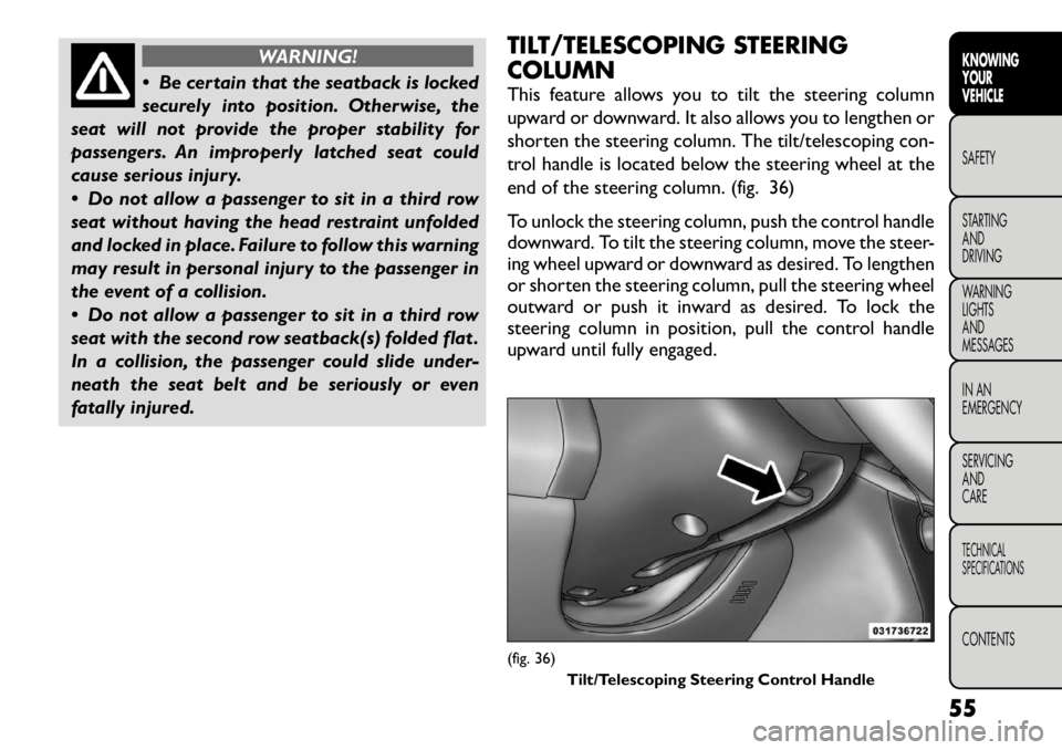
end of the steering column. (fig. 36)
To unlock the steering column, push the control handle
downward. To tilt the steering column, move the steer-
ing wheel upward or downward as desired. To lengthen
or shorten the steering column, pull the steering wheel
outward or push it inward as desired. To lock the
steering column in position, pull the control handle
upward until fully engaged.
(fig. 36)
Tilt/Telescoping Steering Control Handle
55
KNOWING
YOURVEHICLESAFETY
STARTING ANDDRIVING
WARNING LIGHTSAND
MESSAGES
IN AN
EMERGENCY
SERVICING AND
CARETECHNICAL
SPECIFICATIONSCONTENTS
Page 62 of 332
WARNING!
Do not adjust the steering column while
driving. Adjusting the steering column
while driving or driving with the steering column
unlocked could cause the driver to lose control of
the vehicle. Be sure the steering column is locked
before driving your vehicle. Failure to follow this
warning may result in serious injury or death. MIRRORS
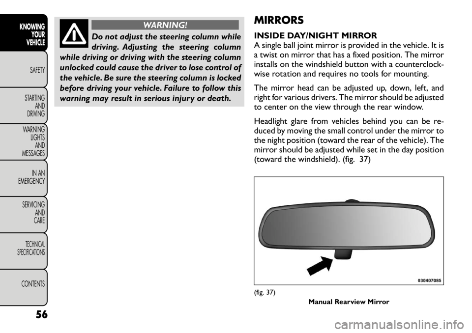
INSIDE DAY/NIGHT MIRROR
A single ball joint mirror is provided in the vehicle. It is
a twist on mirror that has a fixed position. The mirror
installs on the windshield button with a counterclock-
wise rotation and requires no tools for mounting.
The mirror head can be adjusted up, down, left, and
right for various drivers. The mirror should be adjusted
to center on the view through the rear window.
Headlight glare from vehicles behind you can be re-
duced by moving the small control under the mirror to
the night position (toward the rear of the vehicle). The
mirror should be adjusted while set in the day position
(toward the windshield). (fig. 37)
(fig. 37)
Manual Rearview Mirror
56
KNOWING YOUR
VEHICLE
SAFETY
STARTING AND
DRIVING
WARNING LIGHTSAND
MESSAGES
IN AN
EMERGENCY
SERVICING AND
CARETECHNICAL
SPECIFICATIONSCONTENTS
Page 65 of 332
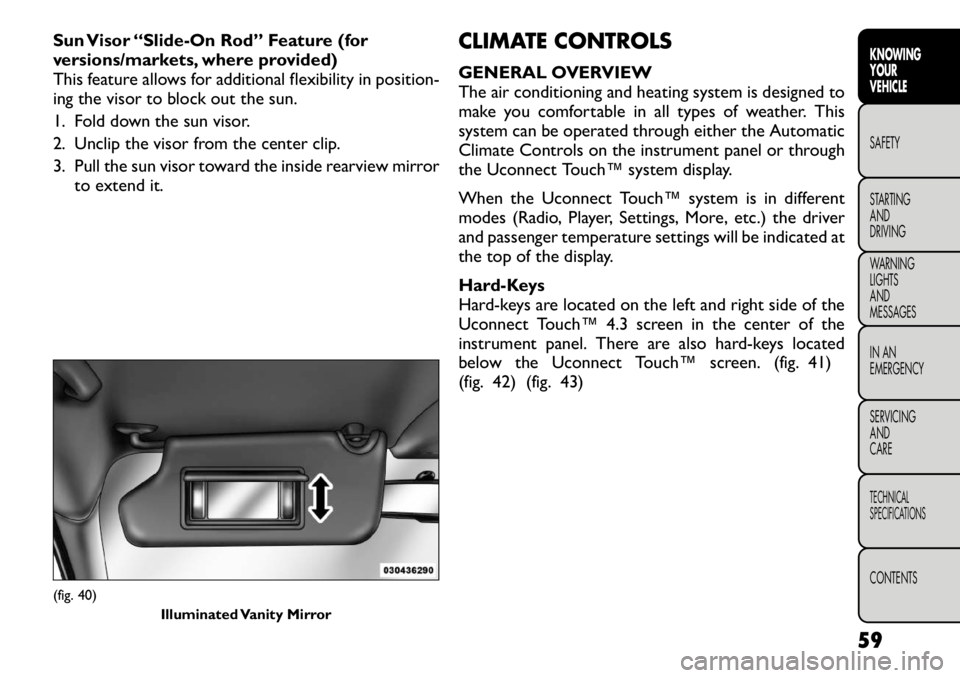
Sun Visor “Slide-On Rod” Feature (for
versions/markets, where provided)
This feature allows for additional flexibility in position-
ing the visor to block out the sun.
1. Fold down the sun visor.
2. Unclip the visor from the center clip.
3. Pull the sun visor toward the inside rearview mirrorto extend it. CLIMATE CONTROLS
GENERAL OVERVIEW
The air conditioning and heating system is designed to
make you comfortable in all types of weather. This
system can be operated through either the Automatic
Climate Controls on the instrument panel or through
the Uconnect Touch™ system display.
When the Uconnect Touch™ system is in different
modes (Radio, Player, Settings, More, etc.) the driver
and passenger temperature settings will be indicated at
the top of the display.
Hard-Keys
Hard-keys are located on the left and right side of the
Uconnect Touch™ 4.3 screen in the center of the
instrument panel. There are also hard-keys located
below the Uconnect Touch™ screen. (fig. 41)
(fig. 42) (fig. 43)(fig. 40)
Illuminated Vanity Mirror
59
KNOWING
YOURVEHICLESAFETY
STARTING ANDDRIVING
WARNING LIGHTSAND
MESSAGES
IN AN
EMERGENCY
SERVICING AND
CARETECHNICAL
SPECIFICATIONSCONTENTS
Page 67 of 332
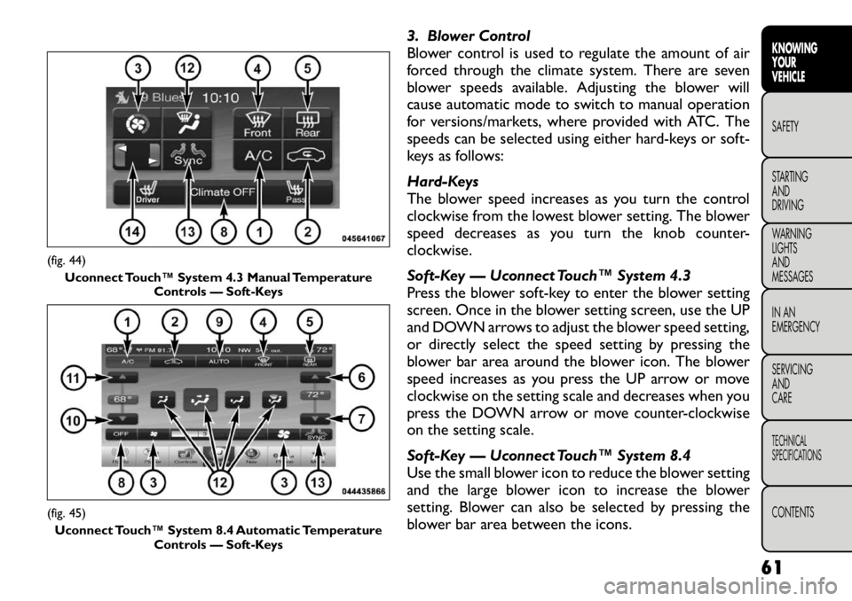
3. Blower Control
Blower control is used to regulate the amount of air
forced through the climate system. There are seven
blower speeds available. Adjusting the blower will
cause automatic mode to switch to manual operation
for versions/markets, where provided with ATC. The
speeds can be selected using either hard-keys or soft-
keys as follows:
Hard-Keys
The blower speed increases as you turn the control
clockwise from the lowest blower setting. The blower
speed decreases as you turn the knob counter-
clockwise.
Soft-Key — Uconnect Touch™ System 4.3
Press the blower soft-key to enter the blower setting
screen. Once in the blower setting screen, use the UP
and DOWN arrows to adjust the blower speed setting,
or directly select the speed setting by pressing the
blower bar area around the blower icon. The blower
speed increases as you press the UP arrow or move
clockwise on the setting scale and decreases when you
press the DOWN arrow or move counter-clockwise
on the setting scale.
Soft-Key — Uconnect Touch™ System 8.4
Use the small blower icon to reduce the blower setting
and the large blower icon to increase the blower
setting. Blower can also be selected by pressing the
blower bar area between the icons.
(fig. 44)Uconnect Touch™ System 4.3 Manual Temperature Controls — Soft-Keys(fig. 45)
Uconnect Touch™ System 8.4 Automatic Temperature Controls — Soft-Keys
61
KNOWING
YOURVEHICLESAFETY
STARTING ANDDRIVING
WARNING LIGHTSAND
MESSAGES
IN AN
EMERGENCY
SERVICING AND
CARETECHNICAL
SPECIFICATIONSCONTENTS
Page 72 of 332
REAR AUTOMATIC TEMPERATURE
CONTROL (ATC) (for versions/markets,
where provided)
The rear ATC system has floor air outlets at the rear
right side of the 3rd Row seats and overhead outlets at
each outboard rear seating position. The system pro-
vides heated air through the floor outlets or cool,
dehumidified air through the headliner outlets.
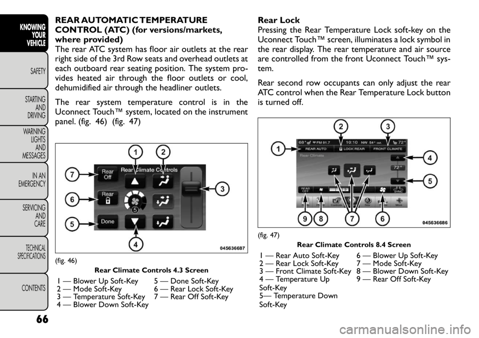
The rear system temperature control is in the
Uconnect Touch™ system, located on the instrument
panel. (fig. 46) (fig. 47)Rear Lock
Pressing the Rear Temperature Lock soft-key on the
Uconnect Touch™ screen, illuminates a lock symbol in
the rear display. The rear temperature and air source
are controlled from the front Uconnect Touch™ sys-
tem.
Rear second row occupants can only adjust the rear
ATC control when the Rear Temperature Lock button
is turned off.(fig. 46)
Rear Climate Controls 4.3 Screen
1 — Blower Up Soft-Key 5 — Done Soft-Key
2 — Mode Soft-Key 6 — Rear Lock Soft-Key
3 — Temperature Soft-Key 7 — Rear Off Soft-Key
4 — Blower Down Soft-Key
(fig. 47) Rear Climate Controls 8.4 Screen
1 — Rear Auto Soft-Key 6 — Blower Up Soft-Key
2 — Rear Lock Soft-Key 7 — Mode Soft-Key
3 — Front Climate Soft-Key 8 — Blower Down Soft-Key
4 — Temperature Up
Soft-Key 9 — Rear Off Soft-Key
5— Temperature Down
Soft-Key
66
KNOWING YOUR
VEHICLE
SAFETY
STARTING AND
DRIVING
WARNING LIGHTSAND
MESSAGES
IN AN
EMERGENCY
SERVICING AND
CARETECHNICAL
SPECIFICATIONSCONTENTS
Page 73 of 332
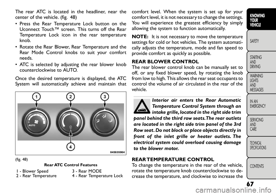
The rear ATC is located in the headliner, near the
center of the vehicle. (fig. 48)
• Press the Rear Temperature Lock button on theUconnect Touch™ screen. This turns off the Rear
Temperature Lock icon in the rear temperature
knob.
• Rotate the Rear Blower, Rear Temperature and the Rear Mode Control knobs to suit your comfortneeds.
• ATC is selected by adjusting the rear blower knob counterclockwise to AUTO.
Once the desired temperature is displayed, the ATC
System will automatically achieve and maintain that comfort level. When the system is set up for your
comfort level, it is not necessary to change the settings.
You will experience the greatest efficiency by simply
allowing the system to function automatically.
NOTE:
It is not necessary to move the temperature
settings for cold or hot vehicles. The system automati-
cally adjusts the temperature, mode and fan speed to
provide comfort as quickly as possible.
REAR BLOWER CONTROL
The rear blower control knob can be manually set to
off, or any fixed blower speed, by rotating the knob
from low to high. This allows the rear seat occupants to
control the volume of air circulated in the rear of the
vehicle.
Interior air enters the Rear Automatic
Temperature Control System through an
intake grille, located in the right side trim
panel behind the third row seats.The rear outlets
are located in the right side trim panel of the 3rd
Row seat . Do not block or place objects directly in
front of the inlet grille or heater outlets. The
electrical system could overload causing damage
to the blower motor.
REAR TEMPERATURE CONTROL
To change the temperature in the rear of the vehicle,
rotate the temperature knob counterclockwise to de-
crease the temperature, and clockwise to increase the
(fig. 48) Rear ATC Control Features
1 - Blower Speed 3 - Rear MODE
2 - Rear Temperature 4 - Rear Temperature Lock
67
KNOWING
YOURVEHICLESAFETY
STARTING ANDDRIVING
WARNING LIGHTSAND
MESSAGES
IN AN
EMERGENCY
SERVICING AND
CARETECHNICAL
SPECIFICATIONSCONTENTS
Page 74 of 332
temperature. The rear temperature settings are dis-
played in the Uconnect Touch™ system.
When rear controls are locked by the Uconnect
Touch™ system , the Rear Temperature Lock symbol
on the temperature knob is illuminated and any rear
overhead adjustments are ignored.
REAR MODE CONTROL
Auto Mode
The rear system automatically maintains the correct
mode and comfort level desired by the rear seat occu-pants.
Headliner ModeAir comes from the outlets in the headliner. Each
of these outlets can be individually adjusted to
direct the flow of air. Moving the air vanes of the
outlets to one side will shut off the airflow.
Bi-Level Mode
Air comes from both the headliner outlets and
the floor outlets.
NOTE: In many temperature positions, the BI-LEVEL
mode is designed to provide cooler air out of the
headliner outlets and warmer air from the floor out-lets.
Floor Mode Air comes from the floor outlets. OPERATING TIPS
NOTE:
Refer to the chart at the end of this section
for suggested control settings for various weather conditions.
Summer Operation
The engine cooling system in air-conditioned vehicles
must be protected with a high-quality antifreeze cool-
ant to provide proper corrosion protection and to
protect against engine overheating. A solution of 50%
ethylene glycol antifreeze coolant and 50% water is
recommended. Refer to “Maintenance Procedures” in
“Servicing And Care” for proper coolant selection.
Winter Operation
Use of the air Recirculation mode during Winter
months is not recommended because it may cause
window fogging.
Vacation Storage
Any time you store your vehicle or keep it out of
service (i.e., vacation) for two weeks or more, run the
air conditioning system at idle for about five minutes in
the fresh air and high blower setting. This will ensure
adequate system lubrication to minimize the possibility
of compressor damage when the system is started
again.
68
KNOWING YOUR
VEHICLE
SAFETY
STARTING AND
DRIVING
WARNING LIGHTSAND
MESSAGES
IN AN
EMERGENCY
SERVICING AND
CARETECHNICAL
SPECIFICATIONSCONTENTS