lock FIAT FREEMONT 2012 Owner handbook (in English)
[x] Cancel search | Manufacturer: FIAT, Model Year: 2012, Model line: FREEMONT, Model: FIAT FREEMONT 2012Pages: 332, PDF Size: 5.61 MB
Page 122 of 332
to operate normally if the Brake System Warning Light
is not on.
If the ABS Light is on, the brake system should be
serviced as soon as possible to restore the benefits of
Anti-Lock brakes. If the ABS Light does not come on
when the ignition switch is turned to the ON position,
have the light repaired as soon as possible.
If both the Brake System Warning Light and the ABS
Light remain on, the ABS and Electronic Brake Force
Distribution (EBD) systems are not functioning. Imme-
diate repair to the ABS system is required.
BRAKE ASSIST SYSTEM (BAS)
The BAS is designed to optimize the vehicle’s braking
capability during emergency braking maneuvers. The
system detects an emergency braking situation by sens-
ing the rate and amount of brake application and then
applies optimum pressure to the brakes. This can help
reduce braking distances. The BAS complements the
ABS. Applying the brakes very quickly results in the
best BAS assistance. To receive the benefit of the
system, you must apply continuous braking pressure
during the stopping sequence, (do not “pump” the
brakes). Do not reduce brake pedal pressure unless
braking is no longer desired. Once the brake pedal is
released, the BAS is deactivated.
WARNING!
BAS cannot prevent the natural laws of
physics from acting on the vehicle, nor
can it increase the traction afforded by prevailing
road conditions. BAS cannot prevent accidents,
including those resulting from excessive speed in
turns, driving on very slippery surfaces, or hydro-
planing. The capabilities of a BAS-equipped ve-
hicle must never be exploited in a reckless or
dangerous manner, which could jeopardize the
user's safety or the safety of others.
TRACTION CONTROL SYSTEM (TCS)
This system monitors the amount of wheel spin of each
of the driven wheels. If wheel spin is detected, brake
pressure is applied to the slipping wheel(s) and engine
power is reduced to provide enhanced acceleration
and stability. A feature of the TCS functions similar to a
limited slip differential and controls the wheel spin
across a driven axle. If one wheel on a driven axle is
spinning faster than the other, the system will apply the
brake of the spinning wheel. This will allow more
engine torque to be applied to the wheel that is not
spinning. This feature remains active even if TCS and
ESC are in the “Partial Off ” mode. Refer to “Electronic
Stability Control (ESC)” for further information.
116
KNOWING YOUR
VEHICLE
SAFETY
STARTING AND
DRIVING
WARNING LIGHTSAND
MESSAGES
IN AN
EMERGENCY
SERVICING AND
CARETECHNICAL
SPECIFICATIONSCONTENTS
Page 151 of 332
markets, where provided) and the VES™ mode is
selected and the disc is stopped, press the SETUP
button to access the DVD Setup menu. (see the
DVD Setup Menu of this manual.)
16. BACK – When navigating in menu mode, press to return to the previous screen. When navigating a
DVDs disc menu, the operation depends on the
disc’s contents.
17. ◂◂– In radio modes, press to seek to the previous
tunable station. In disc modes, press and hold to
fast rewind through the current audio track or
video chapter. In menu modes use to navigate in
the menu.
18. ENTER – Press to select the highlighted option in a menu.
19. ▴/ NEXT – In radio modes, press to select to the
next station. In disc modes, press to advance to
the next audio track or video chapter. In menu
modes, use to navigate in the menu.
Remote Control Storage
The video screen(s) come with a built in storage
compartment for the remote control which is acces-
sible when the screen is opened. To remove the re-
mote, use your index finger to pull and rotate the
remote towards you. Do not try to pull the remote
straight down as it will be very difficult to remove. To
return the remote back into its storage area, insert one
long edge of the remote into the two retaining clips
first, and then rotate the remote back up into the other two retaining clips until it snaps back into position.
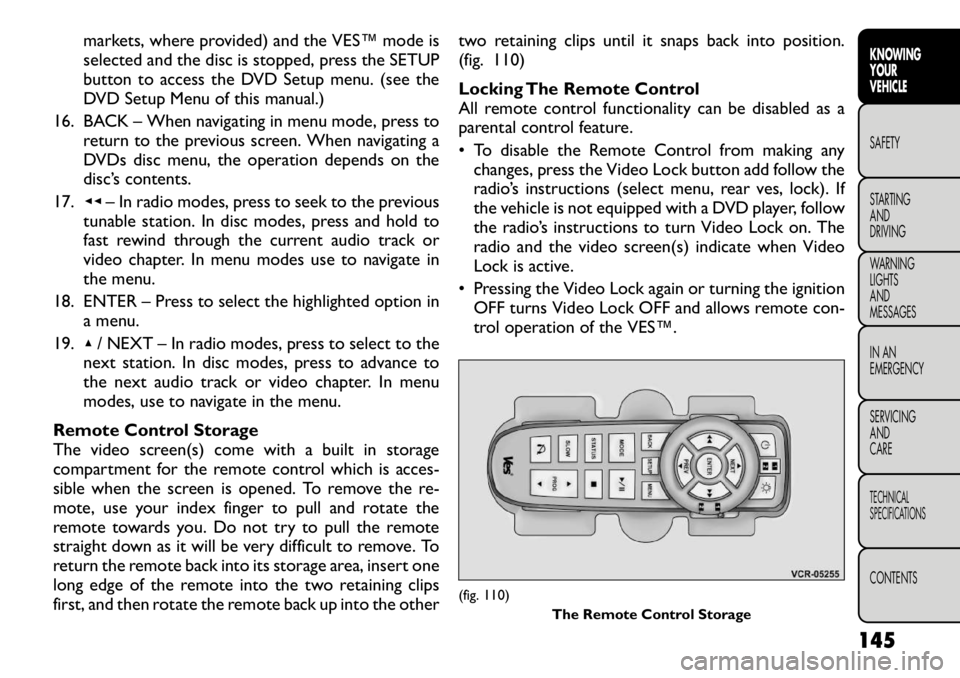
(fig. 110)
Locking The Remote Control
All remote control functionality can be disabled as a
parental control feature.
• To disable the Remote Control from making any
changes, press the Video Lock button add follow the
radio’s instructions (select menu, rear ves, lock). If
the vehicle is not equipped with a DVD player, follow
the radio’s instructions to turn Video Lock on. The
radio and the video screen(s) indicate when Video
Lock is active.
• Pressing the Video Lock again or turning the ignition OFF turns Video Lock OFF and allows remote con-
trol operation of the VES™.
(fig. 110) The Remote Control Storage
145
KNOWING
YOURVEHICLESAFETY
STARTING ANDDRIVING
WARNING LIGHTSAND
MESSAGES
IN AN
EMERGENCY
SERVICING AND
CARETECHNICAL
SPECIFICATIONSCONTENTS
Page 156 of 332
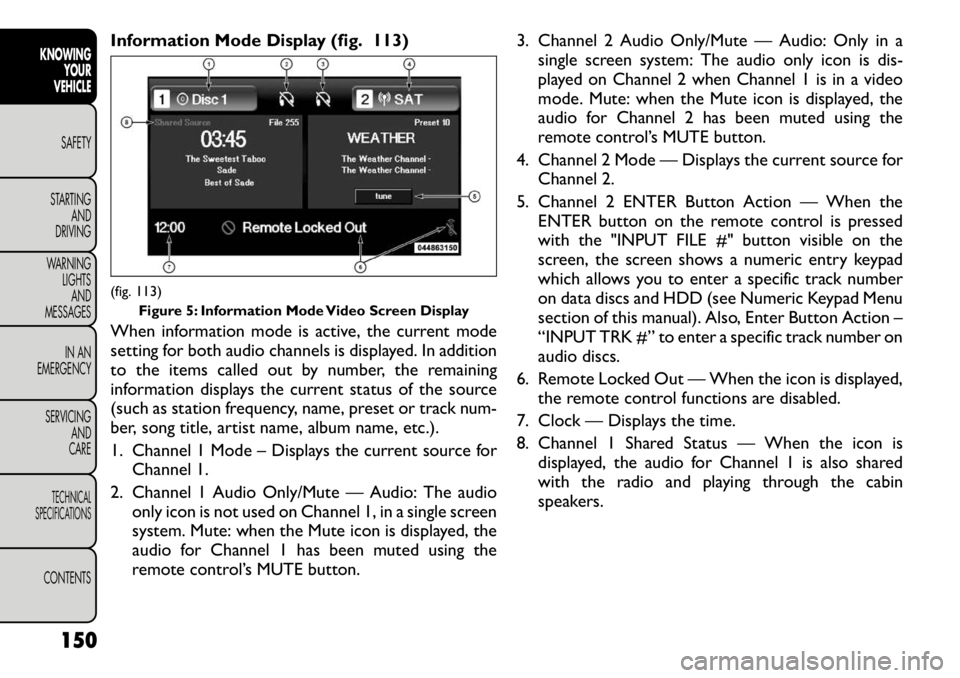
Information Mode Display (fig. 113)
When information mode is active, the current mode
setting for both audio channels is displayed. In addition
to the items called out by number, the remaining
information displays the current status of the source
(such as station frequency, name, preset or track num-
ber, song title, artist name, album name, etc.).
1. Channel 1 Mode – Displays the current source forChannel 1.
2. Channel 1 Audio Only/Mute — Audio: The audio only icon is not used on Channel 1, in a single screen
system. Mute: when the Mute icon is displayed, the
audio for Channel 1 has been muted using the
remote control’s MUTE button. 3. Channel 2 Audio Only/Mute — Audio: Only in a
single screen system: The audio only icon is dis-
played on Channel 2 when Channel 1 is in a video
mode. Mute: when the Mute icon is displayed, the
audio for Channel 2 has been muted using the
remote control’s MUTE button.
4. Channel 2 Mode — Displays the current source for Channel 2.
5. Channel 2 ENTER Button Action — When the ENTER button on the remote control is pressed
with the "INPUT FILE #" button visible on the
screen, the screen shows a numeric entry keypad
which allows you to enter a specific track number
on data discs and HDD (see Numeric Keypad Menu
section of this manual). Also, Enter Button Action –
“INPUT TRK #” to enter a specific track number on
audio discs.
6. Remote Locked Out — When the icon is displayed, the remote control functions are disabled.
7. Clock — Displays the time.
8. Channel 1 Shared Status — When the icon is displayed, the audio for Channel 1 is also shared
with the radio and playing through the cabin
speakers.(fig. 113) Figure 5: Information Mode Video Screen Display
150
KNOWING YOUR
VEHICLE
SAFETY
STARTING AND
DRIVING
WARNING LIGHTSAND
MESSAGES
IN AN
EMERGENCY
SERVICING AND
CARETECHNICAL
SPECIFICATIONSCONTENTS
Page 164 of 332
SAFETY
OCCUPANT RESTRAINTS
Some of the most important safety features in your
vehicle are the restraint systems:
• Three-point lap and shoulder belts for all seating positions
• Advanced Front Air Bags for driver and front passen- ger
• Supplemental Active Head Restraints (AHR) located on top of the front seats (integrated into the head
restraint) (for versions/markets, where provided)
• Supplemental Side Air Bag Inflatable Curtains (SABIC) that span the front, second, and third row
seating for the driver and passengers seated next to
a window
• Supplemental Seat-Mounted Side Air Bags
• An energy-absorbing steering column and steering wheel
• Knee bolsters/blockers for front seat occupants (for versions/markets, where provided)
• Front seat belts incorporate pretensioners that may enhance occupant protection by managing occupant
energy during an impact event
• All seat belt systems (except the driver’s) include Automatic Locking Retractors (ALRs), which lock
the seat belt webbing into position by extending the
belt all the way out and then adjusting the belt to the
desired length to restrain a child seat or secure a large item in a seat (for versions/markets, where
provided)
If you will be carrying children too small for adult-sized
seat belts, the seat belts or ISOFIX feature also can be
used to hold infant and child restraint systems. For
more information, refer to ISOFIX — Child Seat An-
chorage System.
NOTE: The Advanced Front Air Bags have a multi-
stage inflator design. This allows the air bag to have
different rates of inflation based on the severity and
type of collision.
Please pay close attention to the information in this
section. It tells you how to use your restraint system
properly, to keep you and your passengers as safe as
possible.
WARNING!
In an accident , you and your passengers
can suffer much greater injuries if you
are not properly buckled up. You can strike the
interior of your vehicle or other passengers, or
you can be thrown out of the vehicle. Always be
sure you and others in your vehicle are buckled
up properly.
158
KNOWING YOUR
VEHICLESAFETYSTARTING AND
DRIVING
WARNING LIGHTS
AND
MESSAGES
IN AN
EMERGENCY
SERVICING AND
CARETECHNICAL
SPECIFICATIONSCONTENTS
Page 165 of 332
Buckle up even though you are an excellent driver, even
on short trips. Someone on the road may be a poor
driver and cause an accident that includes you. This can
happen far away from home or on your own street.
Research has shown that seat belts save lives, and they
can reduce the seriousness of injuries in an accident.
Some of the worst injuries happen when people are
thrown from the vehicle. Seat belts reduce the possi-
bility of ejection and the risk of injury caused by striking
the inside of the vehicle. Everyone in a motor vehicle
should be belted at all times.
LAP/SHOULDER BELTS
All seating positions in your vehicle are equipped with
a combination lap/shoulder belts.
The belt webbing retractor is designed to lock during
very sudden stops or impacts. This feature allows the
shoulder part of the belt to move freely with you under
normal conditions. However, in an accident, the belt
will lock and reduce your risk of striking the inside of
the vehicle or being thrown out.
WARNING!
It is dangerous to ride in a cargo area,
inside or outside of a vehicle. In an acci-
dent , people riding in these areas are more likely
to be seriously injured or killed.
(Continued)(Continued)
Do not allow people to ride in any area of your
vehicle that is not equipped with seats and seat
belts.
Be sure everyone in your vehicle is in a seat and
using a seat belt properly.
No modifications or additions should be made
by the user, which will either prevent the seat belt
adjusting devices from operating to remove
slack, or prevent the seat belt assembly from
being adjusted to remove slack.
Seat belts are designed to bear upon the bony
structure of the body, and should be worn low
across the front of the pelvis or the pelvis, chest
and shoulders, as applicable; wearing the lap
section of the belt across the abdominal area
must be avoided.
Seat belts should be adjusted as firmly as pos-
sible, consistent with comfort , to provide the
protection for which they have been designed. A
slack belt will greatly reduce the protection af-
forded to the wearer.
Each belt assembly must only be used by one
occupant ; it is dangerous to put a belt around a
child being carried on an occupant's lap.
(Continued)
159
KNOWING
YOURVEHICLESAFETYSTARTING ANDDRIVING
WARNING LIGHTSAND
MESSAGES
IN AN
EMERGENCY
SERVICING AND
CARETECHNICAL
SPECIFICATIONSCONTENTS
Page 168 of 332
5. Position the shoulder belt on your chest so that it iscomfortable and not resting on your neck. The
retractor will withdraw any slack in the belt.
6. To release the belt, push the red button on the buckle. The belt will automatically retract to its
stowed position. If necessary, slide the latch plate
down the webbing to allow the belt to retract fully.
WARNING!
A frayed or torn belt could rip apart in
an accident and leave you with no pro-
tection. Inspect the belt system periodically,
checking for cuts, frays, or loose parts. Damaged
parts must be replaced immediately. Do not dis-
assemble or modify the system. Seat belt assem-
blies must be replaced after an accident if they
have been damaged (bent retractor, torn web-
bing, etc .).
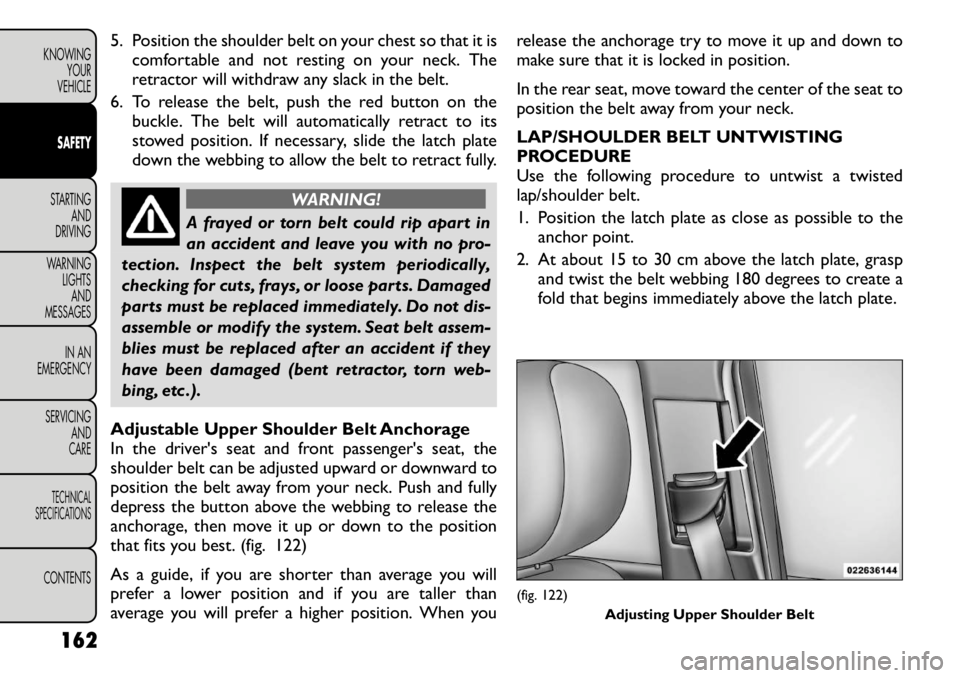
Adjustable Upper Shoulder Belt Anchorage
In the driver's seat and front passenger's seat, the
shoulder belt can be adjusted upward or downward to
position the belt away from your neck. Push and fully
depress the button above the webbing to release the
anchorage, then move it up or down to the position
that fits you best. (fig. 122)
As a guide, if you are shorter than average you will
prefer a lower position and if you are taller than
average you will prefer a higher position. When you release the anchorage try to move it up and down to
make sure that it is locked in position.
In the rear seat, move toward the center of the seat to
position the belt away from your neck.
LAP/SHOULDER BELT UNTWISTING
PROCEDURE
Use the following procedure to untwist a twisted
lap/shoulder belt.
1. Position the latch plate as close as possible to the
anchor point.
2. At about 15 to 30 cm above the latch plate, grasp and twist the belt webbing 180 degrees to create a
fold that begins immediately above the latch plate.
(fig. 122)
Adjusting Upper Shoulder Belt
162
KNOWING YOUR
VEHICLESAFETYSTARTING AND
DRIVING
WARNING LIGHTSAND
MESSAGES
IN AN
EMERGENCY
SERVICING AND
CARETECHNICAL
SPECIFICATIONSCONTENTS
Page 169 of 332
3. Slide the latch plate upward over the folded web-bing. The folded webbing must enter the slot at the
top of the latch plate.
4. Continue to slide the latch plate up until it clears the folded webbing.
SEAT BELTS IN PASSENGER SEATING
POSITIONS
The seat belts in the passenger seating positions are
equipped with an Automatic Locking Retractor (ALR)
or a cinching latch plate which are used to secure a
child restraint system. For additional information refer
to “Installing Child Restraints Using the Vehicle Seat
Belt” under the “Child Restraint” section. The chart
below defines the type of feature for each seatingposition.
Driver Center Passenger
First Row N/A N/A ALR
Second Row ALR ALR ALR
• N/A — Not Applicable
• ALR — Automatic Locking Retractor
If the passenger seating position is equipped with an
ALR and is being used for normal usage:
Only pull the belt webbing out far enough to comfort-
ably wrap around the occupant's mid-section so as to
not activate the ALR. If the ALR is activated, you will
hear a ratcheting sound as the belt retracts. Allow the
webbing to retract completely in this case and then
carefully pull out only the amount of webbing neces- sary to comfortably wrap around the occupant's mid-
section. Slide the latch plate into the buckle until you
hear a "click."
AUTOMATIC LOCKING RETRACTOR MODE
(ALR) (for versions/markets, where provided)
In this mode, the shoulder belt is automatically pre-
locked. The belt will still retract to remove any slack in
the shoulder belt. The Automatic Locking Mode is
available on all passenger-seating positions with a com-
bination lap/shoulder belt. Use the Automatic Locking
Mode anytime a child safety seat is installed in a seating
position that has a belt with this feature. Children
12 years old and under should always be properly
restrained in the rear seat.
How To Engage The Automatic Locking Mode
1. Buckle the combination lap and shoulder belt.
2. Grasp the shoulder portion and pull downward until
the entire belt is extracted.
3. Allow the belt to retract. As the belt retracts, you will hear a clicking sound. This indicates the safety
belt is now in the Automatic Locking Mode.
How To Disengage The Automatic LockingMode
Unbuckle the combination lap/shoulder belt and allow
it to retract completely to disengage the Automatic
Locking Mode and activate the vehicle sensitive (emer-
gency) locking mode.
163
KNOWING
YOURVEHICLESAFETYSTARTING ANDDRIVING
WARNING LIGHTSAND
MESSAGES
IN AN
EMERGENCY
SERVICING AND
CARETECHNICAL
SPECIFICATIONSCONTENTS
Page 170 of 332
WARNING!
The belt and retractor assembly must
be replaced if the seat belt assembly
Automatic Locking Retractor (ALR) feature or
any other seat belt function is not working prop-
erly when checked according to the procedures in
the Service Manual.
Failure to replace the belt and retractor assem-
bly could increase the risk of injury in collisions.
SEAT BELT PRETENSIONERS
The seat belts for both front seating positions are
equipped with pretensioning devices that are designed
to remove slack from the seat belt in the event of an
accident. These devices may improve the performance
of the seat belt by assuring that the belt is tight about
the occupant early in an accident. Pretensioners work
for all size occupants, including those in child restraints.
NOTE: These devices are not a substitute for proper
seat belt placement by the occupant. The seat belt still
must be worn snugly and positioned properly.
The pretensioners are triggered by the Occupant Re-
straint Controller (ORC). Like the air bags, the preten-
sioners are single use items. A deployed pretensioner
or a deployed air bag must be replaced immediately. SUPPLEMENTAL ACTIVE HEAD
RESTRAINTS (AHR) (for versions/markets,
where provided)
These head restraints are passive, deployable compo-
nents, and vehicles with this equipment cannot be
readily identified by any markings, only through visual
inspection of the head restraint. The head restraint will
be split in two halves, with the front half being soft
foam and trim, the back half being decorative plastic.
How The Active Head Restraints (AHR) Work
The Occupant Restraint Controller (ORC) determines
whether the severity, or type of rear impact will require
the Active Head Restraints (AHR) to deploy. If a rear
impact requires deployment, both the driver and front
passenger seat AHRs will be deployed.
When AHRs deploy during a rear impact, the front half
of the head restraint extends forward to minimize the
gap between the back of the occupant’s head and the
AHR. This system is designed to help prevent or
reduce the extent of injuries to the driver and front
passenger in certain types of rear impacts.
NOTE:
The Active Head Restraints (AHR) may or
may not deploy in the event of a front or side impact.
However if during a front impact, a secondary rear
impact occurs, the AHR may deploy based on the
severity and type of the impact. (fig. 123)
164
KNOWING YOUR
VEHICLESAFETYSTARTING AND
DRIVING
WARNING LIGHTSAND
MESSAGES
IN AN
EMERGENCY
SERVICING AND
CARETECHNICAL
SPECIFICATIONSCONTENTS
Page 172 of 332
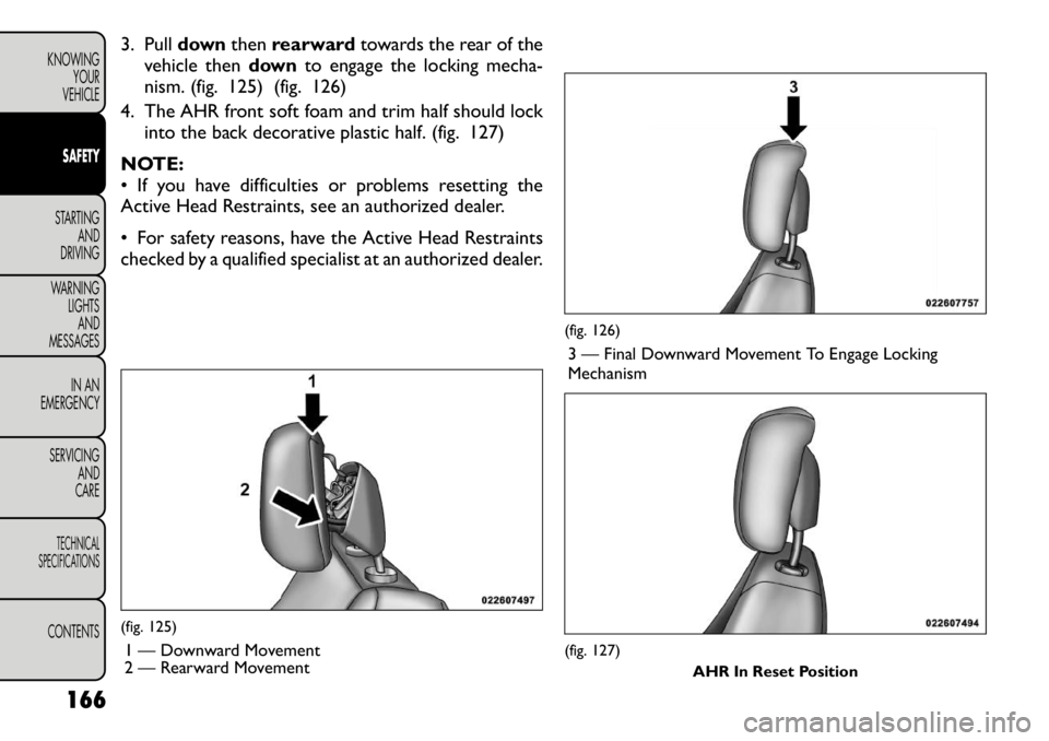
3. Pulldownthenrearward towards the rear of the
vehicle then downto engage the locking mecha-
nism. (fig. 125) (fig. 126)
4. The AHR front soft foam and trim half should lock into the back decorative plastic half. (fig. 127)
NOTE:
• If you have difficulties or problems resetting the
Active Head Restraints, see an authorized dealer.
• For safety reasons, have the Active Head Restraints
checked by a qualified specialist at an authorized dealer.(fig. 125) 1 — Downward Movement
2 — Rearward Movement
(fig. 126)3 — Final Downward Movement To Engage Locking Mechanism(fig. 127) AHR In Reset Position
166
KNOWING YOUR
VEHICLESAFETYSTARTING AND
DRIVING
WARNING LIGHTSAND
MESSAGES
IN AN
EMERGENCY
SERVICING AND
CARETECHNICAL
SPECIFICATIONSCONTENTS
Page 173 of 332
ACTIVE HOOD SYSTEM (for versions/
markets, where provided)
The Active Hood system is intended to enhance pe-
destrian protection by elevating the vehicle’s hood
upon an impact with a pedestrian or other object. The
system is automatically activated when the vehicle is
moving within a specified vehicle speed range. In order
to detect a range of pedestrians, other objects that are
impacted may result in an Active Hood deployment.
Deployment Sensors And Controls
The Electronic Pedestrian Protection Module (EPPM)
determines if deployment of the actuators in a frontal
impact is required. Based on the impact sensors signals,
the EPPM determines when to deploy the actuators.
The impact sensors are located within the front bum-
per area.
The EPPM monitors the readiness of the electronic
parts of the Active Hood system whenever the ignition
switch is in the START or ON/RUN position. If the key
is in the LOCK position, in the ACC position, or not in
the ignition, the Active Hood system is not on and the
Active Hood will not deploy.
The EPPM contains a backup power supply system that
may deploy the actuators even if the battery loses
power or it becomes disconnected prior to
deployment.Service Active Hood System
If the EPPM has deployed the Active Hood, or if it
detects a malfunction in any part of the system, it turns
on the Air Bag Warning Light and it will display the
“SERVICE ACTIVE HOOD” message in the Electronic
Vehicle Information Center (EVIC), for versions/
markets, where provided. A single chime will sound if
the Air Bag Warning Light comes on again after initial
startup. It also includes diagnostics that will illuminate
the Air Bag Warning Light if a malfunction is noted that
could affect the Active Hood system. The diagnostics
also record the nature of the malfunction. If the Air Bag
Warning Light is illuminated, or if “SERVICE ACTIVE
HOOD” appears in the EVIC, see your authorized
dealer.
In the event of an Active Hood deployment, the vehicle
should be serviced by an authorized dealer. The hood
hinges must be serviced and the actuator assemblies
replaced to restore system functionality.
Following an Active Hood deployment, the hood posi-
tion can be temporarily reset by pushing down at the
rear edge over the hood hinges as the internal pressure
of each actuator is relieved. The temporary hood reset
position is intended to improve forward driving visibil-
ity over the hood until the vehicle can be serviced. The
temporary hood reset position will leave the hood
approximately 5 mm above the fender surface.
(fig. 128)
167
KNOWING
YOURVEHICLESAFETYSTARTING ANDDRIVING
WARNING LIGHTSAND
MESSAGES
IN AN
EMERGENCY
SERVICING AND
CARETECHNICAL
SPECIFICATIONSCONTENTS