engine FIAT FREEMONT 2012 Owner handbook (in English)
[x] Cancel search | Manufacturer: FIAT, Model Year: 2012, Model line: FREEMONT, Model: FIAT FREEMONT 2012Pages: 332, PDF Size: 5.61 MB
Page 227 of 332
Automatic Transmission (for versions/markets,
where provided)
The DRIVE range can be selected when towing. How-
ever, if frequent shifting occurs while in this range,
select a lower gear (using the AutoStick
®
shift con-
trol).
NOTE: Using a lower gear while operating the ve-
hicle under heavy operating conditions will improve
performance and extend transmission life by reducing
excessive shifting and heat build up. This action will also
provide better engine braking.
If you REGULARLY tow a trailer for more than 45 min-
utes of continuous operation, then change the trans-
mission fluid and automatic transmission filter accord-
ing to the interval specified for “police, taxi, fleet, or
frequent trailer towing.” Refer to the “Maintenance
Schedule” for the proper maintenance intervals.
Electronic Speed Control (for versions/
markets, where provided)
� Do not use in hilly terrain or with heavy loads.
� When using the speed control, if you experience speed drops greater than 16 km/h, disengage until you can get
back to cruising speed.
� Use speed control in flat terrain and with light loads to maximize fuel efficiency.
AutoStick
®
� By using the AutoStick
®shift control to select a specific
gear, frequent shifting can be avoided. Select the highest
gear that allows for adequate performance. For example,
choose “4” if the desired speed can be maintained.
Choose “3” or “2” if needed to maintain the desiredspeed.
� Extended driving at high RPM should be avoided to pr e-
vent excess heat generation. A reduction in vehicle speed
may be required to avoid extended driving at high RPM.
Return to a higher gear or vehicle speed when road
conditions and RPM level allows.
Cooling System
To reduce potential for engine and transmission over-
heating, take the following actions:� City DrivingWhen stopped for short periods, shift the transmission
into NEUTRAL and increase engine idle speed.� Highway DrivingReduce speed.� Air ConditioningTurn off temporarily.
TRAILER HITCH ATTACHING POINTS
Your vehicle will require extra equipment to tow a
trailer safely and efficiently. The trailer tow hitch must
be attached to your vehicle using the provided attach-
ing points on the vehicle's frame. Refer to the following
221
KNOWING
YOURVEHICLE SAFETYSTARTING ANDDRIVINGWARNING LIGHTSAND
MESSAGES
IN AN
EMERGENCY
SERVICING AND
CARETECHNICAL
SPECIFICATIONSCONTENTS
Page 231 of 332
INSTRUMENT CLUSTER DESCRIPTIONS
1. Air Bag Warning LightThis light will turn on for four to eight sec-
onds as a bulb check when the ignition switch
is first turned to ON/RUN. If the light is
either not on during starting, stays on, or
turns on while driving, have the system inspected at an
authorized dealer as soon as possible. Refer to “Occu-
pant Restraints” in “Safety” for further information.
2. Malfunction Indicator Light (MIL) The Malfunction Indicator Light (MIL) is part of
an onboard diagnostic system, called OBD, that
monitors engine and transmission control sys-
tems. The light will illuminate when the key is in the
ON/RUN position, before engine start. If the bulb does
not come on when turning the key from OFF to
ON/RUN, have the condition checked promptly.
Certain conditions, such as a loose or missing gas cap,
poor fuel quality, etc., may illuminate the MIL after
engine start. The vehicle should be serviced if the MIL
stays on through several of your typical driving cycles.
In most situations, the vehicle will drive normally and
will not require towing.
Prolonged driving with the MIL on could
cause damage to the engine control sys-
tem. It also could affect fuel economy
and drivability. If the MIL is flashing, severe cata-
lytic converter damage and power loss will soon
occur. Immediate service is required.
WARNING!
A malfunctioning catalytic converter, as
referenced above, can reach higher tem-
peratures than in normal operating conditions.
This can cause a fire if you drive slowly or park
over flammable substances such as dry plants,
wood, cardboard, etc .This could result in death or
serious injury to the driver, occupants or others.
3. Electronic Stability Control (ESC)
Activation/Malfunction Indicator Light (for
versions/markets, where provided) The “ESC Activation/Malfunction Indicator
Light” in the instrument cluster will come on
when the ignition switch is turned to the
ON/RUN position. It should go out with the
engine running. If the “ESC Activation/Malfunction In-
dicator Light” comes on continuously with the engine
running, a malfunction has been detected in the ESC
system. If this light remains on after several ignition
225KNOWING
YOURVEHICLE SAFETY
STARTING ANDDRIVINGWARNING LIGHTSAND
MESSAGESIN AN
EMERGENCY
SERVICING AND
CARETECHNICAL
SPECIFICATIONSCONTENTS
Page 237 of 332
IN AN EMERGENCY
JUMP-STARTING
If your vehicle has a discharged battery, it can be
jump-started using a set of jumper cables and a battery
in another vehicle or by using a portable battery
booster pack. Jump-starting can be dangerous if done
improperly so please follow the procedures in this
section carefully.
NOTE: When using a portable battery booster pack
follow the manufacturer's operating instructions and
precautions.
Do not use a portable battery booster
pack or any other booster source with a
system voltage greater than 12 Volts or
damage to the battery, starter motor, alternator
or electrical system may occur.
WARNING!
Do not attempt jump-starting if the bat-
tery is frozen. It could rupture or explode
and cause personal injury. PREPARATIONS FOR JUMP-START
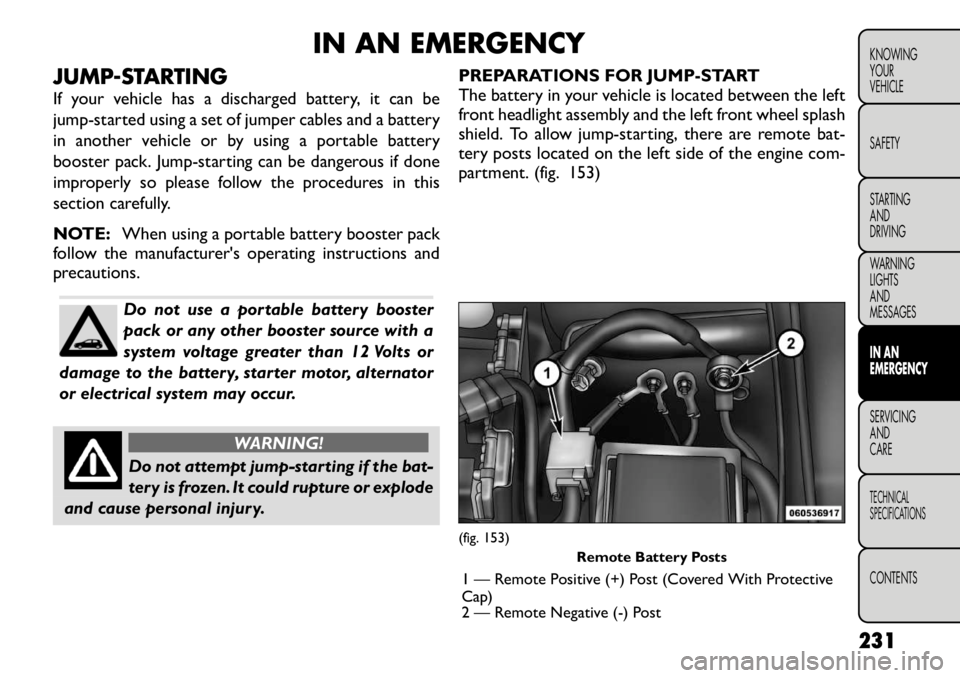
The battery in your vehicle is located between the left
front headlight assembly and the left front wheel splash
shield. To allow jump-starting, there are remote bat-
tery posts located on the left side of the engine com-
partment. (fig. 153)
(fig. 153)
Remote Battery Posts
1 — Remote Positive (+) Post (Covered With Protective
Cap)
2 — Remote Negative (-) Post
231
KNOWING
YOURVEHICLE SAFETY
STARTING ANDDRIVING
WARNING LIGHTSAND
MESSAGESIN AN
EMERGENCYSERVICING AND
CARETECHNICAL
SPECIFICATIONSCONTENTS
Page 239 of 332
WARNING!
Do not connect the cable to the negative
post(-)of the discharged battery. The
resulting electrical spark could cause the battery
to explode and could result in personal injury.
5. Start the engine in the vehicle that has the booster battery, let the engine idle a few minutes, and then
start the engine in the vehicle with the discharged
battery.
Once the engine is started, remove the jumper
cables in the reverse sequence:
6. Disconnect the negative (-)jumper cable from the
remote negative (-)post of the vehicle with the
discharged battery.
7. Disconnect the negative end (-)of the jumper cable
from the negative (-)post of the booster battery.
8. Disconnect the opposite end of the positive (+)
jumper cable from the positive (+)post of the
booster battery.
9. Disconnect the positive (+)end of the jumper cable
from the remote positive (+)post of the discharged
vehicle.
10. Reinstall the protective cover over the remote positive (+)battery post of the discharged vehicle. If frequent jump-starting is required to start your
vehicle, you should have the battery and charging
system inspected at your authorized dealer.
Accessories that can be plugged into the
vehicle power outlets draw power from
the vehicle’s battery, even when not in
use (i.e., cellular phones, etc .). Eventually, if
plugged in long enough, the vehicle’s battery will
discharge sufficiently to degrade battery life
and/or prevent the engine from starting.
233
KNOWING
YOURVEHICLE SAFETY
STARTING ANDDRIVING
WARNING LIGHTSAND
MESSAGESIN AN
EMERGENCYSERVICING AND
CARETECHNICAL
SPECIFICATIONSCONTENTS
Page 240 of 332
JACKING AND TIRE CHANGING
WARNING!
Do not attempt to change a tire on the
side of the vehicle close to moving traf-
fic . Pull far enough off the road to avoid the
danger of being hit when operating the jack or
changing the wheel.
Being under a jacked-up vehicle is dangerous.
The vehicle could slip off the jack and fall on you.
You could be crushed. Never put any part of your
body under a vehicle that is on a jack. If you need
to get under a raised vehicle, take it to a service
center where it can be raised on a lift .
Never start or run the engine while the vehicle
is on a jack.
The jack is designed to be used as a tool for
changing tires only.The jack should not be used to
lift the vehicle for service purposes. The vehicle
should be jacked on a firm level surface only.
Avoid ice or slippery areas. JACK LOCATION
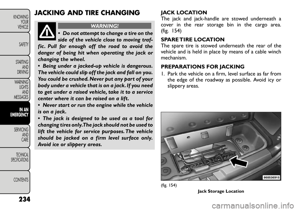
The jack and jack-handle are stowed underneath a
cover in the rear storage bin in the cargo area.
(fig. 154)
SPARE TIRE LOCATION
The spare tire is stowed underneath the rear of the
vehicle and is held in place by means of a cable winchmechanism.
PREPARATIONS FOR JACKING
1. Park the vehicle on a firm, level surface as far from
the edge of the roadway as possible. Avoid icy or
slippery areas.
(fig. 154)
Jack Storage Location
234
KNOWING YOUR
VEHICLE
SAFETY
STARTING AND
DRIVING
WARNING LIGHTSAND
MESSAGES
IN AN
EMERGENCY
SERVICING AND
CARETECHNICAL
SPECIFICATIONSCONTENTS
Page 243 of 332
(Continued)
Never start or run the engine with the vehicle
on a jack.
Do not let anyone sit in the vehicle when it is on
a jack.
Do not get under the vehicle when it is on a
jack.
Only use the jack in the positions indicated and
for lifting this vehicle during a tire change.
If working on or near a roadway, be extremely
careful of motor traffic .
To assure that spare tires, flat or inflated, are
securely stowed, spares must be stowed with the
valve stem facing the ground.
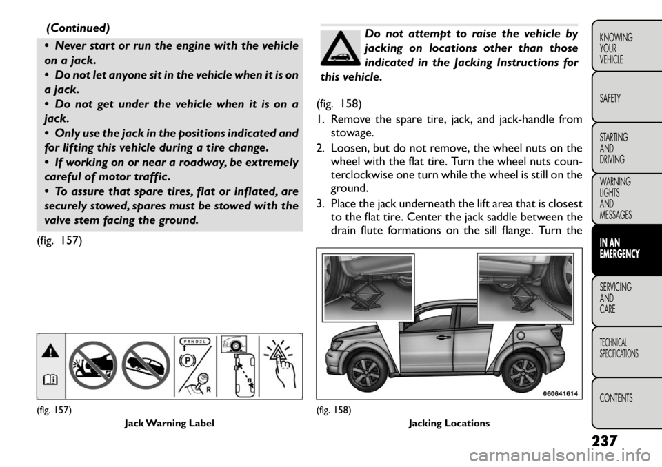
(fig. 157)
Do not attempt to raise the vehicle by
jacking on locations other than those
indicated in the Jacking Instructions for
this vehicle.
(fig. 158)
1. Remove the spare tire, jack, and jack-handle from stowage.
2. Loosen, but do not remove, the wheel nuts on the wheel with the flat tire. Turn the wheel nuts coun-
terclockwise one turn while the wheel is still on the
ground.
3. Place the jack underneath the lift area that is closest to the flat tire. Center the jack saddle between the
drain flute formations on the sill flange. Turn the
(fig. 157)
Jack Warning Label
(fig. 158) Jacking Locations
237
KNOWING
YOURVEHICLE SAFETY
STARTING ANDDRIVING
WARNING LIGHTSAND
MESSAGESIN AN
EMERGENCYSERVICING AND
CARETECHNICAL
SPECIFICATIONSCONTENTS
Page 251 of 332
vehicle as necessary to place the valve stem in this
position before proceeding.
3. Place the transmission in PARK (auto transmission) or in Gear (manual transmission) and turn Off theignition.
4. Set the parking brake.
(B) Setting Up To Use TIREFIT:
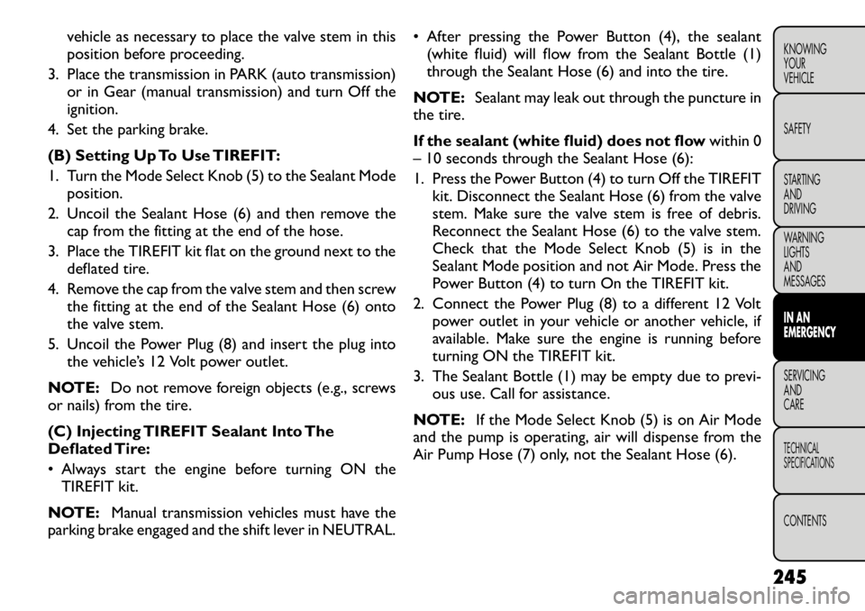
1. Turn the Mode Select Knob (5) to the Sealant Mode position.
2. Uncoil the Sealant Hose (6) and then remove the cap from the fitting at the end of the hose.
3. Place the TIREFIT kit flat on the ground next to the deflated tire.
4. Remove the cap from the valve stem and then screw the fitting at the end of the Sealant Hose (6) onto
the valve stem.
5. Uncoil the Power Plug (8) and insert the plug into the vehicle’s 12 Volt power outlet.
NOTE: Do not remove foreign objects (e.g., screws
or nails) from the tire.
(C) Injecting TIREFIT Sealant Into The
Deflated Tire:
• Always start the engine before turning ON the
TIREFIT kit.
NOTE: Manual transmission vehicles must have the
parking brake engaged and the shift lever in NEUTRAL. • After pressing the Power Button (4), the sealant
(white fluid) will flow from the Sealant Bottle (1)
through the Sealant Hose (6) and into the tire.
NOTE: Sealant may leak out through the puncture in
the tire.
If the sealant (white fluid) does not flow within 0
– 10 seconds through the Sealant Hose (6):
1. Press the Power Button (4) to turn Off the TIREFIT
kit. Disconnect the Sealant Hose (6) from the valve
stem. Make sure the valve stem is free of debris.
Reconnect the Sealant Hose (6) to the valve stem.
Check that the Mode Select Knob (5) is in the
Sealant Mode position and not Air Mode. Press the
Power Button (4) to turn On the TIREFIT kit.
2. Connect the Power Plug (8) to a different 12 Volt power outlet in your vehicle or another vehicle, if
available. Make sure the engine is running before
turning ON the TIREFIT kit.
3. The Sealant Bottle (1) may be empty due to previ- ous use. Call for assistance.
NOTE: If the Mode Select Knob (5) is on Air Mode
and the pump is operating, air will dispense from the
Air Pump Hose (7) only, not the Sealant Hose (6).
245
KNOWING
YOURVEHICLE SAFETY
STARTING ANDDRIVING
WARNING LIGHTSAND
MESSAGESIN AN
EMERGENCYSERVICING AND
CARETECHNICAL
SPECIFICATIONSCONTENTS
Page 262 of 332
UNDERHOOD FUSES (POWER
DISTRIBUTION CENTER)
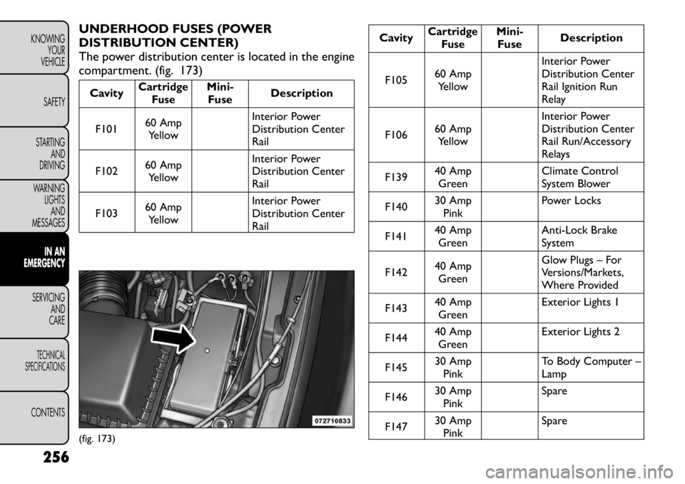
The power distribution center is located in the engine
compartment. (fig. 173)Cavity
CartridgeFuse
Mini-Fuse Description
F101 60 Amp
Yellow Interior Power
Distribution CenterRail
F102 60 Amp
Yellow Interior Power
Distribution CenterRail
F103 60 Amp
Yellow Interior Power
Distribution CenterRail
Cavity
Cartridge
Fuse
Mini-Fuse Description
F105 60 Amp
Yellow Interior Power
Distribution Center
Rail Ignition Run
Relay
F106 60 Amp
Yellow Interior Power
Distribution Center
Rail Run/Accessory
Relays
F139 40 Amp
Green Climate Control
System Blower
F140 30 Amp
Pink Power Locks
F141 40 Amp
Green Anti-Lock Brake
System
F142 40 Amp
Green Glow Plugs – For
Versions/Markets,
Where Provided
F143 40 Amp
Green Exterior Lights 1
F144 40 Amp
Green Exterior Lights 2
F145 30 Amp
Pink To Body Computer –Lamp
F146 30 Amp
Pink Spare
F147 30 Amp
Pink Spare
(fig. 173)
256
KNOWING YOUR
VEHICLE
SAFETY
STARTING AND
DRIVING
WARNING LIGHTSAND
MESSAGES
IN AN
EMERGENCY
SERVICING AND
CARETECHNICAL
SPECIFICATIONSCONTENTS
Page 265 of 332
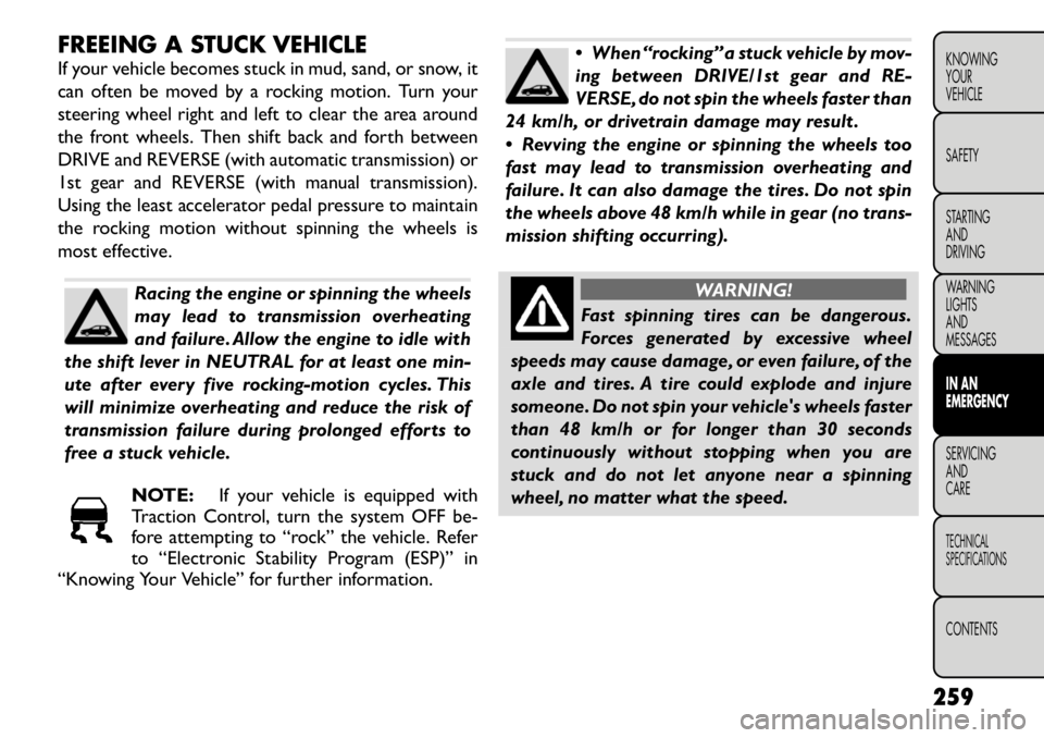
FREEING A STUCK VEHICLE
If your vehicle becomes stuck in mud, sand, or snow, it
can often be moved by a rocking motion. Turn your
steering wheel right and left to clear the area around
the front wheels. Then shift back and forth between
DRIVE and REVERSE (with automatic transmission) or
1st gear and REVERSE (with manual transmission).
Using the least accelerator pedal pressure to maintain
the rocking motion without spinning the wheels is
most effective.
Racing the engine or spinning the wheels
may lead to transmission overheating
and failure. Allow the engine to idle with
the shift lever in NEUTRAL for at least one min-
ute after every five rocking-motion cycles. This
will minimize overheating and reduce the risk of
transmission failure during prolonged efforts to
free a stuck vehicle.
NOTE: If your vehicle is equipped with
Traction Control, turn the system OFF be-
fore attempting to “rock” the vehicle. Refer
to “Electronic Stability Program (ESP)” in
“Knowing Your Vehicle” for further information.
When “rocking” a stuck vehicle by mov-
ing between DRIVE/1st gear and RE-
VERSE, do not spin the wheels faster than
24 km/h, or drivetrain damage may result .
Revving the engine or spinning the wheels too
fast may lead to transmission overheating and
failure. It can also damage the tires. Do not spin
the wheels above 48 km/h while in gear (no trans-
mission shifting occurring).
WARNING!
Fast spinning tires can be dangerous.
Forces generated by excessive wheel
speeds may cause damage, or even failure, of the
axle and tires. A tire could explode and injure
someone. Do not spin your vehicle's wheels faster
than 48 km/h or for longer than 30 seconds
continuously without stopping when you are
stuck and do not let anyone near a spinning
wheel, no matter what the speed.
259KNOWING
YOURVEHICLE SAFETY
STARTING ANDDRIVING
WARNING LIGHTSAND
MESSAGESIN AN
EMERGENCYSERVICING AND
CARETECHNICAL
SPECIFICATIONSCONTENTS
Page 270 of 332
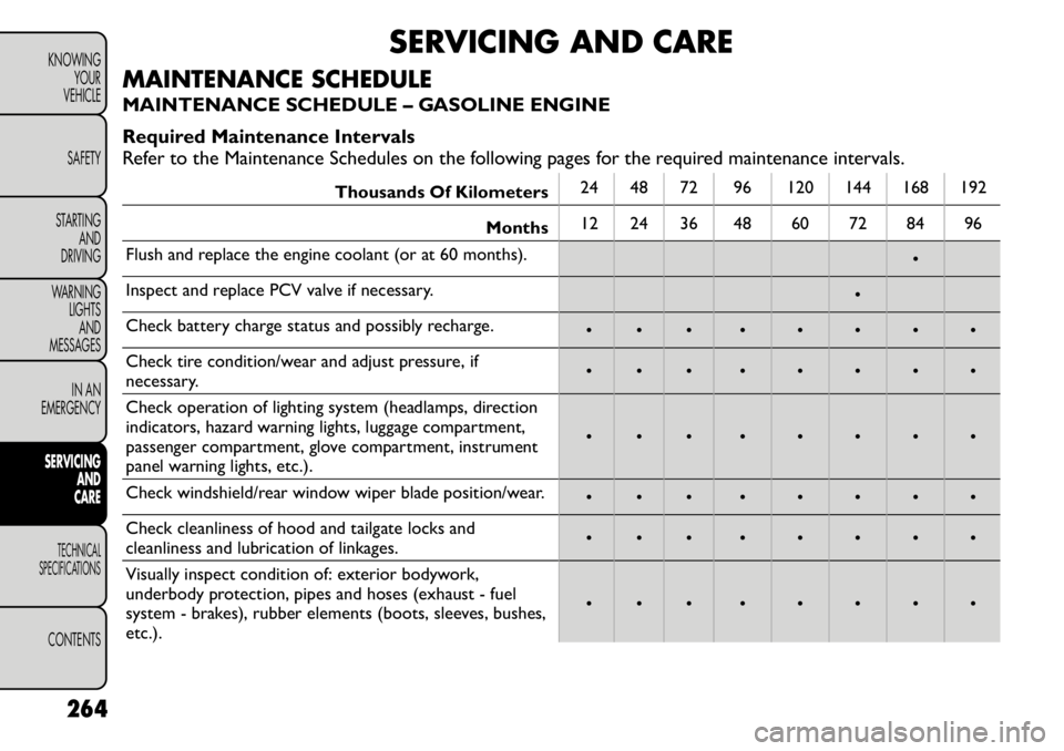
SERVICING AND CARE
MAINTENANCE SCHEDULE
MAINTENANCE SCHEDULE – GASOLINE ENGINE
Required Maintenance Intervals
Refer to the Maintenance Schedules on the following pages for the required maintenance intervals.
Thousands Of Kilometers 24 48 72 96 120 144 168 192
Months 12 24 36 48 60 72 84 96
Flush and replace the engine coolant (or at 60 months). •
Inspect and replace PCV valve if necessary. •
Check battery charge status and possibly recharge. • • • • • • • •
Check tire condition/wear and adjust pressure, if
necessary. • • • • • • • •
Check operation of lighting system (headlamps, direction
indicators, hazard warning lights, luggage compartment,
passenger compartment, glove compartment, instrument
panel warning lights, etc.). • • • • • • • •
Check windshield/rear window wiper blade position/wear. • • • • • • • •
Check cleanliness of hood and tailgate locks and
cleanliness and lubrication of linkages. • • • • • • • •
Visually inspect condition of: exterior bodywork,
underbody protection, pipes and hoses (exhaust - fuel
system - brakes), rubber elements (boots, sleeves, bushes,
etc.). • • • • • • • •
264
KNOWING YOUR
VEHICLE
SAFETY
STARTING AND
DRIVING
WARNING LIGHTS
AND
MESSAGES
IN AN
EMERGENCYSERVICING AND
CARETECHNICAL
SPECIFICATIONSCONTENTS