brake light FIAT FREEMONT 2013 Owner handbook (in English)
[x] Cancel search | Manufacturer: FIAT, Model Year: 2013, Model line: FREEMONT, Model: FIAT FREEMONT 2013Pages: 352, PDF Size: 5.22 MB
Page 257 of 352

raise the spare tire into the storage area. Continue
to rotate the jack-handle assembly until you hear
the winch mechanism click three times. It cannot be
over tightened. Push against the tire several times to
be sure it is held securely in place.
JACKING INSTRUCTIONS
WARNING!
Carefully follow these tire changing
w
arnings to help prevent personal injury
or damage to your vehicle:
Always park on a firm, level surface as far from the
edge of the roadway as possible before raising the
vehicle.
Turn on the Hazard Warning flashers.
Block the wheel diagonally opposite the wheel
to be raised.
Set the parking brake firmly and set an auto-
matic transmission in PARK; a manual transmis-
sion in REVERSE.
Never start or run the engine with the vehicle
on a jack.
Do not let anyone sit in the vehicle when it is
on a jack.
(Continued)(Continued)
Do not get under the vehicle when it is on a
jack. If you need to get under a raised vehicle,
take it to a service center where it can be raised
on a lift .
Only use the jack in the positions indicated
and for lifting this vehicle during a tire change.
If working on or near a roadway, be extremely
careful of motor traffic .
To assure that spare tires, flat or inflated, are
securely stowed, spares must be stowed with the
valve stem facing the ground.
(fig. 153)
(fig. 153) Jack Warning Label
251
KNOWING
YOUR
VEHICLE
SAFETY
STARTING
AND
DRIVING
WARNING
LIGHTS
AND
MESSAGES
IN AN
EMERGENCY
SERVICING
AND
C ARETECHNICAL
SPECIFICATIONSCONTENTS
Page 260 of 352
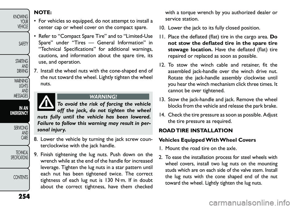
NOTE:
For vehicles so equipped, do not attempt to install acenter cap or wheel cover on the compact spare.
Refer to “Compact Spare Tire” and to “Limited-Use Spare” under “Tires — General Information” in
“Technical Specifications” for additional warnings,
cautions, and information about the spare tire, its
use, and operation.
7. Install the wheel nuts with the cone-shaped end of the nut toward the wheel. Lightly tighten the wheel
nuts.
WARNING!
To avoid the risk of forcing the vehicle
of
f the jack, do not tighten the wheel
nuts fully until the vehicle has been lowered.
Failure to follow this warning may result in per-
sonal injury.
8. Lower the vehicle by turning the jack screw coun- terclockwise with the jack handle.
9. Finish tightening the lug nuts. Push down on the wrench while at the end of the handle for increased
leverage. Tighten the lug nuts in a star pattern until
each nut has been tightened twice. The correct
tightness of each lug nut is 130 N·m. If in doubt
about the correct tightness, have them checked with a torque wrench by you authorized dealer or
service station.
10. Lower the jack to its fully closed position.
11. Place the deflated (flat) tire in the cargo area. Do
not stow the deflated tire in the spare tire
stowage location. Have the deflated (flat) tire
repaired or replaced as soon as possible.
12. To stow the winch cable and retainer, fit the assembled jack-handle over the winch drive nut.
Rotate the jack-handle assembly clockwise until
you hear the winch mechanism click three times. It
cannot be over tightened.
13. Stow the jack-handle and jack. Remove the wheel blocks from the vehicle and release the park brake.
14. Check the tire pressure as soon as possible. Adjust the tire pressure as required.
ROAD TIRE INSTALLATION
Vehicles Equipped With Wheel Covers
1. Mount the road tire on the axle.
2.
To ease the installation process for steel wheels with
wheel covers, install two lug nuts on the mounting
studs which are on each side of the valve stem. Install
the lug nuts with the cone shaped end of the nut
toward the wheel. Lightly tighten the lug nuts.
254
KNOWING YOUR
VEHICLE
SAFETY
STARTING AND
DRIVING
WARNING LIGHTSAND
MESSAGES
IN AN
EMERGENC
Y
SERVICING AND
C
ARETECHNICAL
SPECIFICATIONSCONTENTS
Page 266 of 352

If the tire inflates to the recommended pres-
sure or is at least 1.8 Bar pressure within 15
minutes:
1. Press the Power Button (4) to turn off the TIREFITkit.
2. Remove the Speed Limit sticker from the top of the Sealant Bottle (1) and place the sticker on the
instrument panel.
3. Immediately disconnect the Sealant Hose (6) from the valve stem, reinstall the cap on the fitting at the
end of the hose, and place the TIREFIT kit in the
vehicle storage location. Quickly proceed to (D)
“Drive Vehicle”.
The metal end fitting from Power Plug
(8) may get hot after use, so it should be
handled carefully.
Failure to reinstall the cap on the fitting at the
end of the Sealant Hose (6) can result in sealant
contacting your skin, clothing, and the vehicle’s
interior. It can also result in sealant contacting
internalTIREFIT kit components which may cause
permanent damage to the kit .
(A) Whenever You Stop To Use TIREFIT:
1. Pull over to a safe location and turn on the vehicle’s Hazard Warning flashers. 2. Verify that the valve stem (on the wheel with the
deflated tire) is in a position that is near to the
ground. This will allow the TIREFIT Hoses (6) and
(7) to reach the valve stem and keep the TIREFIT kit
flat on the ground. This will provide the best posi-
tioning of the kit when injecting the sealant into the
deflated tire and running the air pump. Move the
vehicle as necessary to place the valve stem in this
position before proceeding.
3. Place the transmission in PARK (auto transmission) or in Gear (manual transmission) and turn Off the
ignition.
4. Set the parking brake.
(B) Setting Up To Use TIREFIT:
1. Turn the Mode Select Knob (5) to the Sealant Mode position.
2. Uncoil the Sealant Hose (6) and then remove the cap from the fitting at the end of the hose.
3. Place the TIREFIT kit flat on the ground next to the deflated tire.
4. Remove the cap from the valve stem and then screw the fitting at the end of the Sealant Hose (6) onto
the valve stem.
5. Uncoil the Power Plug (8) and insert the plug into the vehicle’s 12 Volt power outlet.
260
KNOWING YOUR
VEHICLE
SAFETY
STARTING AND
DRIVING
WARNING LIGHTSAND
MESSAGES
IN AN
EMERGENC
Y
SERVICING AND
C
ARETECHNICAL
SPECIFICATIONSCONTENTS
Page 267 of 352

NOTE:Do not remove foreign objects (e.g., screws
or nails) from the tire.
(C) Injecting TIREFIT Sealant Into The
Deflated Tire:
Always start the engine before turning ON the TIREFIT kit.
NOTE: Manual transmission vehicles must have the
parking brake engaged and the shift lever in NEUTRAL.
After pressing the Power Button (4), the sealant (white fluid) will flow from the Sealant Bottle (1)
through the Sealant Hose (6) and into the tire.
NOTE: Sealant may leak out through the puncture in
the tire.
If the sealant (white fluid) does not flow within 0
– 10 seconds through the Sealant Hose (6):
1. Press the Power Button (4) to turn Off the TIREFIT kit. Disconnect the Sealant Hose (6) from the valve
stem. Make sure the valve stem is free of debris.
Reconnect the Sealant Hose (6) to the valve stem.
Check that the Mode Select Knob (5) is in the
Sealant Mode position and not Air Mode. Press the
Power Button (4) to turn On the TIREFIT kit.
2. Connect the Power Plug (8) to a different 12 Volt power outlet in your vehicle or another vehicle, if available. Make sure the engine is running before
turning ON the TIREFIT kit.
3. The Sealant Bottle (1) may be empty due to previ- ous use. Call for assistance.
NOTE: If the Mode Select Knob (5) is on Air Mode
and the pump is operating, air will dispense from the
Air Pump Hose (7) only, not the Sealant Hose (6).
If the sealant (white fluid) does flow through the
Sealant Hose (6):
1. Continue to operate the pump until sealant is no longer flowing through hose (typically takes 30 - 70
seconds). As the sealant flows through the Sealant
Hose (6), the Pressure Gauge (3) can read as high as
70 psi (5 Bar). The Pressure Gauge (3) will decrease
quickly from approximately 70 psi (5 Bar) to the
actual tire pressure when the Sealant Bottle (1) is
empty.
2. The pump will start to inject air into the tire immediately after the Sealant Bottle (1) is empty.
Continue to operate the pump and inflate the tire
to the pressure indicated on the tire pressure label
on the driver-side latch pillar (recommended pres-
sure). Check the tire pressure by looking at the
Pressure Gauge (3).
261
KNOWING
YOUR
VEHICLE
SAFETY
STARTING
AND
DRIVING
WARNING
LIGHTS
AND
MESSAGES
IN AN
EMERGENCY
SERVICING
AND
C ARETECHNICAL
SPECIFICATIONSCONTENTS
Page 279 of 352
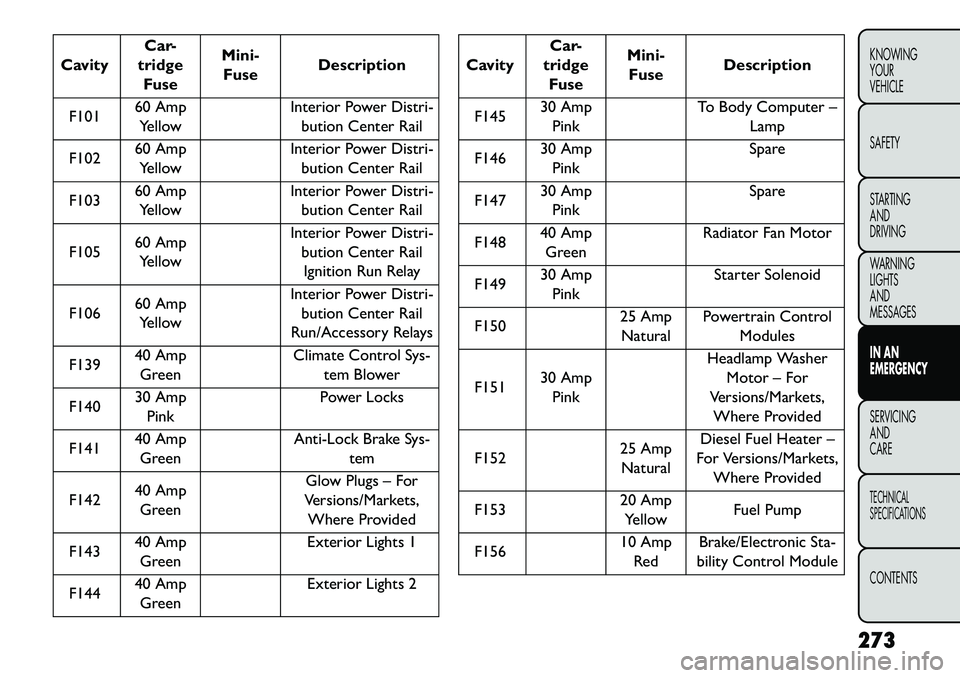
CavityCar-
tridge Fuse Mini-
Fuse Description
F101 60 Amp
Yellow Interior Power Distri-
bution Center Rail
F102 60 Amp
Yellow Interior Power Distri-
bution Center Rail
F103 60 Amp
Yellow Interior Power Distri-
bution Center Rail
F105 60 Amp
Yellow Interior Power Distri-
bution Center RailIgnition Run Relay
F106 60 Amp
Yellow Interior Power Distri-
bution Center Rail
Run/Accessory Relays
F139 40 Amp
Green Climate Control Sys-
tem Blower
F140 30 Amp
Pink Power Locks
F141 40 Amp
Green Anti-Lock Brake Sys-
tem
F142 40 Amp
Green Glow Plugs – For
Versions/Markets, Where Provided
F143 40 Amp
Green Exterior Lights 1
F144 40 Amp
Green Exterior Lights 2
Cavity
Car-
tridge Fuse Mini-
Fuse Description
F145 30 Amp
Pink To Body Computer –
Lamp
F146 30 Amp
Pink Spare
F147 30 Amp
Pink Spare
F148 40 Amp
Green Radiator Fan Motor
F149 30 Amp
Pink Starter Solenoid
F150 25 Amp
Natural Powertrain Control
Modules
F151 30 Amp
Pink Headlamp Washer
Motor – For
Versions/Markets, Where Provided
F152 25 Amp
Natural Diesel Fuel Heater –
For Versions/Markets, Where Provided
F153 20 Amp
Yellow Fuel Pump
F156 10 Amp
Red Brake/Electronic Sta-
bility Control Module
273
KNOWING
YOUR
VEHICLE
SAFETY
STARTING
AND
DRIVING
WARNING
LIGHTS
AND
MESSAGES
IN AN
EMERGENCY
SERVICING
AND
C ARETECHNICAL
SPECIFICATIONSCONTENTS
Page 280 of 352

CavityCar-
tridge Fuse Mini-
Fuse Description
F157 10 Amp
Red Transfer Case Mod-
ule – For Versions/
Markets, Where Pro- vided
F158 10 Amp
Red Active Hood Module
– For Versions/
Markets, Where Pro-
vided
F159 10 Amp
Red Spare
F160 20 Amp
Yellow Interior Lights
F161 20 Amp
Yellow Horn
F162 50 Amp
Red Cabin Heater #1/
Vacuum Pump – For Versions/Markets,Where Provided
F163 50 Amp
Red Cabin Heater #2 –
For Versions/Markets,
Where Provided
F164 25 Amp
Natural Powertrain Auto
Shutdown
F165 20 Amp
Yellow Powertrain Shutdown
Cavity Car-
tridge Fuse Mini-
Fuse Description
F166 20 Amp
Yellow Spare
F167 30 Amp
Green Powertrain Shutdown
F168 10 Amp
Red Air Conditioner
Clutch
F169 40 Amp
Green Emissions – Partial
Zero Emissions Ve- hicle Motor
F170 15 Amp
Blue Emissions – Partial
Zero Emissions Ve- hicle Actuators
F172 20 Amp
Yellow Spare
F173 25 Amp
Natural Anti Lock Brake
Valves
F174 20 Amp
Yellow Siren – For Versions/
Markets, Where Pro- vided
F175 30 Amp
Green Spare
F176 10 Amp
Red Powertrain Control
Modules
274
KNOWING YOUR
VEHICLE
SAFETY
STARTING AND
DRIVING
WARNING LIGHTSAND
MESSAGES
IN AN
EMERGENC
Y
SERVICING AND
C
ARETECHNICAL
SPECIFICATIONSCONTENTS
Page 281 of 352
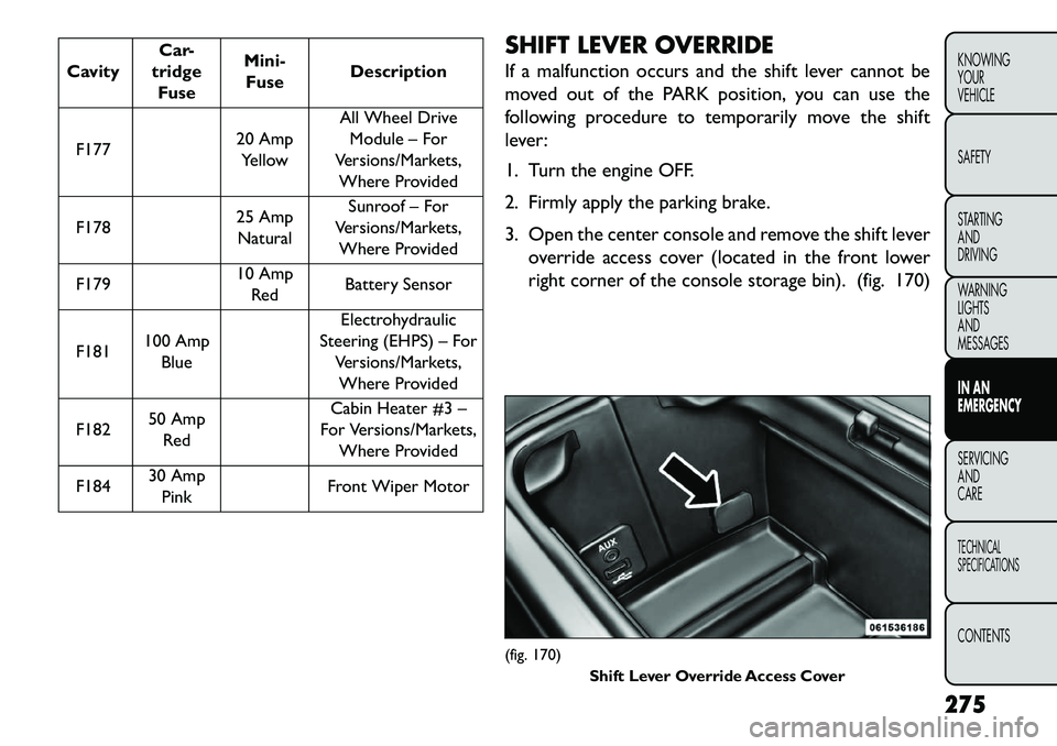
CavityCar-
tridge Fuse Mini-
Fuse Description
F177 20 Amp
Yellow All Wheel Drive
Module – For
Versions/Markets, Where Provided
F178 25 Amp
Natural Sunroof – For
Versions/Markets, Where Provided
F179 10 Amp
Red Battery Sensor
F181 100 Amp
Blue Electrohydraulic
Steering (EHPS) – For Versions/Markets,Where Provided
F182 50 Amp
Red Cabin Heater #3 –
For Versions/Markets, Where Provided
F184 30 Amp
Pink Front Wiper Motor SHIFT LEVER OVERRIDE
If a malfunction occurs and the shift lever cannot be
moved out of the PARK position, you can use the
following procedure to temporarily move the shift
lever:
1. Turn the engine OFF.
2. Firmly apply the parking brake.
3. Open the center console and remove the shift lever
override access cover (located in the front lower
right corner of the console storage bin). (fig. 170)
(fig. 170) Shift Lever Override Access Cover
275
KNOWING
YOUR
VEHICLE
SAFETY
STARTING
AND
DRIVING
WARNING
LIGHTS
AND
MESSAGES
IN AN
EMERGENCY
SERVICING
AND
C ARETECHNICAL
SPECIFICATIONSCONTENTS
Page 282 of 352
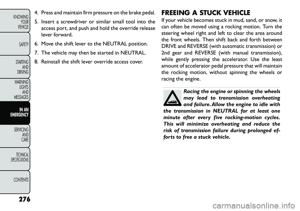
4. Press and maintain firm pressure on the brake pedal.
5. Insert a screwdriver or similar small tool into theaccess port, and push and hold the override release
lever forward.
6. Move the shift lever to the NEUTRAL position.
7. The vehicle may then be started in NEUTRAL.
8. Reinstall the shift lever override access cover. FREEING A STUCK VEHICLE
If your vehicle becomes stuck in mud, sand, or snow, it
can often be moved using a rocking motion. Turn the
steering wheel right and left to clear the area around
the front wheels. Then shift back and forth between
DRIVE and REVERSE (with automatic transmission) or
2nd gear and REVERSE (with manual transmission),
while gently pressing the accelerator. Use the least
amount of accelerator pedal pressure that will maintain
the rocking motion, without spinning the wheels or
racing the engine.
Racing the engine or spinning the wheels
may lead to transmission overheating
and failure. Allow the engine to idle with
the transmission in NEUTRAL for at least one
minute after every five rocking-motion cycles.
This will minimize overheating and reduce the
risk of transmission failure during prolonged ef-
forts to free a stuck vehicle.
276
KNOWING YOUR
VEHICLE
SAFETY
STARTING AND
DRIVING
WARNING LIGHTSAND
MESSAGES
IN AN
EMERGENC
Y
SERVICING AND
C
ARETECHNICAL
SPECIFICATIONSCONTENTS
Page 283 of 352
NOTE:Press the "ESC Off" switch, to place the
Electronic Stability Control (ESC) system in
"Partial Off" mode, before rocking the ve-
hicle. Refer to “Electronic Brake Control” in
“Knowing Your Vehicle” for further informa-
tion. Once the vehicle has been freed, press the "ESC
Off" switch again to restore "ESC On" mode.
When “rocking” a stuck vehicle by
shifting between DRIVE and REVERSE,
do not spin the wheels faster than
15 mph (24 km/h), or drivetrain damage may
result .
Revving the engine or spinning the wheels too
fast may lead to transmission overheating and
failure. It can also damage the tires. Do not spin
the wheels above 30 mph (48 km/h) while in gear
(no transmission shifting occurring).
WARNING!
Fast spinning tires can be dangerous.
F
orces generated by excessive wheel
speeds may cause damage, or even failure, of the
axle and tires. A tire could explode and injure
someone. Do not spin your vehicle's wheels faster
than 48 km/h or for longer than 30 seconds
continuously without stopping when you are
stuck and do not let anyone near a spinning
wheel, no matter what the speed.
277KNOWING
YOUR
VEHICLE
SAFETY
STARTING
AND
DRIVING
WARNING
LIGHTS
AND
MESSAGES
IN AN
EMERGENC Y
SERVICING
AND
C ARETECHNICAL
SPECIFICATIONSCONTENTS
Page 290 of 352
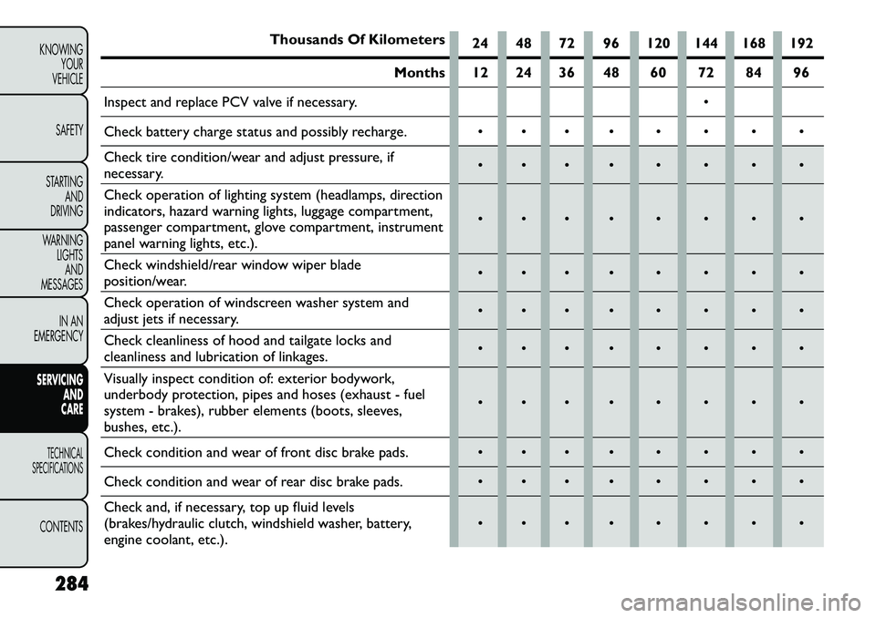
Thousands Of Kilometers24 48 72 96 120 144 168 192
Months 12 24 36 48 60 72 84 96
Inspect and replace PCV valve if necessary.
Check battery charge status and possibly recharge.
Check tire condition/wear and adjust pressure, if
necessary.
Check operation of lighting system (headlamps, direction
indicators, hazard warning lights, luggage compartment,
passenger compartment, glove compartment, instrument
panel warning lights, etc.).
Check windshield/rear window wiper blade
position/wear.
Check operation of windscreen washer system and
adjust jets if necessary.
Check cleanliness of hood and tailgate locks and
cleanliness and lubrication of linkages.
Visually inspect condition of: exterior bodywork,
underbody protection, pipes and hoses (exhaust - fuel
system - brakes), rubber elements (boots, sleeves,
bushes, etc.).
Check condition and wear of front disc brake pads.
Check condition and wear of rear disc brake pads.
Check and, if necessary, top up fluid levels
(brakes/hydraulic clutch, windshield washer, battery,
engine coolant, etc.).
284
KNOWING YOUR
VEHICLE
SAFETY
STARTING AND
DRIVING
WARNING LIGHTSAND
MESSAGES
IN AN
EMERGENCY
SERVICING AND
C
ARETECHNICAL
SPECIFICATIONSCONTENTS