buttons FIAT IDEA 2008 1.G User Guide
[x] Cancel search | Manufacturer: FIAT, Model Year: 2008, Model line: IDEA, Model: FIAT IDEA 2008 1.GPages: 210, PDF Size: 3.64 MB
Page 54 of 210
53
SAFETY
DEVICES
CORRECT USE
OF THE CAR
WARNING
LIGHTS AND
MESSAGES
IN AN
EMERGENCY
CAR
MAINTENANCE
TECHNICAL
SPECIFICATIONS
INDEX
DASHBOARD
AND CONTROLS
During fully automatic operation, the on-
ly manual settings required are the fol-
lowing:
❒MONO, to align the air temperature
and distribution set on the passenger’s
side (front or rear) with that on the
driver’s side;
❒…, air recirculation, to keep it al-
ways on or off;
❒-, to speed up demisting/defrosting
of windscreen, front side windows,
rear window and door mirrors;
❒(, to demist/defrost the rear heat-
ed window and the door mirrors.
During completely automatic system op-
eration, the temperatures, air distribution
and the fan speed set can be changed at
any time through the relevant buttons or
knobs: the system will automatically
change its settings to adjust to the new re-
quirements.
During full automatic operation (FULL
AUTO), any change in air distribution
and/or air flow and/or compressor turn-
ing on and/or air recirculation will obtain
FULLdisappearing. In this way functions
will be controlled manually until pressing
the AUTObutton again. The fan speed is
the same for all passenger compartment
areas.With one or more functions engaged man-
ually, the adjustment of the temperature
of the air admitted to the passenger com-
partment continues to be controlled au-
tomatically by the system, except with the
climate control compressor off. In fact, in
this condition, the air admitted to the pas-
senger compartment cannot have a low-
er temperature than the outside air.
CONTROLS
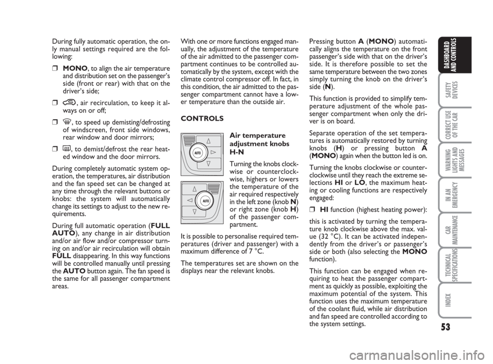
Air temperature
adjustment knobs
H-N
Turning the knobs clock-
wise or counterclock-
wise, highers or lowers
the temperature of the
air required respectively
in the left zone (knob N)
or right zone (knob H)
of the passenger com-
partment.
It is possible to personalise required tem-
peratures (driver and passenger) with a
maximum difference of 7 °C.
The temperatures set are shown on the
displays near the relevant knobs.Pressing button A(MONO) automati-
cally aligns the temperature on the front
passenger’s side with that on the driver’s
side. It is therefore possible to set the
same temperature between the two zones
simply turning the knob on the driver’s
side (N).
This function is provided to simplify tem-
perature adjustment of the whole pas-
senger compartment when only the dri-
ver is on board.
Separate operation of the set tempera-
tures is automatically restored by turning
knobs (H) or pressing button A
(MONO) again when the button led is on.
Turning the knobs clockwise or counter-
clockwise until they reach the extreme se-
lections HIor LO, the maximum heat-
ing or cooling functions are respectively
engaged:
❒HIfunction (highest heating power):
this is activated by turning the tempera-
ture knob clockwise above the max. val-
ue (32 °C). It can be activated indepen-
dently from the driver’s or passenger’s
side or both (also selecting the MONO
function).
This function can be engaged when re-
quiring to heat the passenger compart-
ment as quickly as possible, exploiting the
maximum potential of the system. This
function uses the maximum temperature
of the coolant fluid, while air distribution
and fan speed are controlled according to
the system settings.
036-092 idea GB 1 ed 10-07-2008 16:12 Pagina 53
Page 55 of 210
54
SAFETY
DEVICES
CORRECT USE
OF THE CAR
WARNING
LIGHTS AND
MESSAGES
IN AN
EMERGENCY
CAR
MAINTENANCE
TECHNICAL
SPECIFICATIONS
INDEX
DASHBOARD
AND CONTROLS
More particularly, max. fan speed will not
be immediately engaged if coolant is not
hot enough; this to prevent admitting air
that is not warm enough to the passenger
compartment.
All manual settings are however possible
with this function on.
To switch the function off, simply turn the
temperature knob counterclockwise and
set the required temperature.
❒LOfunction (highest cooling power):
this is activated by turning the tempera-
ture knob counterclockwise below the
min. value (16 °C). It can be activated in-
dependently from the driver’s or passen-
ger’s side or both (also selecting the
MONOfunction).
This function can be engaged when re-
quiring to cool the passenger compart-
ment as quickly as possible, exploiting the
maximum potential of the system. This
function engages inside air recirculation
and climate control compressor, while air
distribution and fan speed are controlled
according to environmental conditions. All manual settings are however possible
with this function on.
To switch the function off, simply turn the
temperature knob clockwise and set the
required temperature.
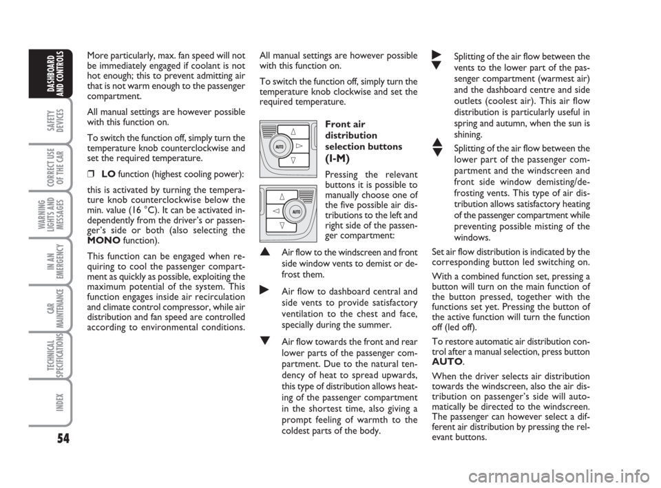
Front air
distribution
selection buttons
(I-M)
Pressing the relevant
buttons it is possible to
manually choose one of
the five possible air dis-
tributions to the left and
right side of the passen-
ger compartment:
▲Air flow to the windscreen and front
side window vents to demist or de-
frost them.
˙Air flow to dashboard central and
side vents to provide satisfactory
ventilation to the chest and face,
specially during the summer.
▼Air flow towards the front and rear
lower parts of the passenger com-
partment. Due to the natural ten-
dency of heat to spread upwards,
this type of distribution allows heat-
ing of the passenger compartment
in the shortest time, also giving a
prompt feeling of warmth to the
coldest parts of the body.
˙
▼Splitting of the air flow between the
vents to the lower part of the pas-
senger compartment (warmest air)
and the dashboard centre and side
outlets (coolest air). This air flow
distribution is particularly useful in
spring and autumn, when the sun is
shining.
▲
▼Splitting of the air flow between the
lower part of the passenger com-
partment and the windscreen and
front side window demisting/de-
frosting vents. This type of air dis-
tribution allows satisfactory heating
of the passenger compartment while
preventing possible misting of the
windows.
Set air flow distribution is indicated by the
corresponding button led switching on.
With a combined function set, pressing a
button will turn on the main function of
the button pressed, together with the
functions set yet. Pressing the button of
the active function will turn the function
off (led off).
To restore automatic air distribution con-
trol after a manual selection, press button
AUTO.
When the driver selects air distribution
towards the windscreen, also the air dis-
tribution on passenger’s side will auto-
matically be directed to the windscreen.
The passenger can however select a dif-
ferent air distribution by pressing the rel-
evant buttons.
036-092 idea GB 1 ed 10-07-2008 16:12 Pagina 54
Page 56 of 210
55
SAFETY
DEVICES
CORRECT USE
OF THE CAR
WARNING
LIGHTS AND
MESSAGES
IN AN
EMERGENCY
CAR
MAINTENANCE
TECHNICAL
SPECIFICATIONS
INDEX
DASHBOARD
AND CONTROLS
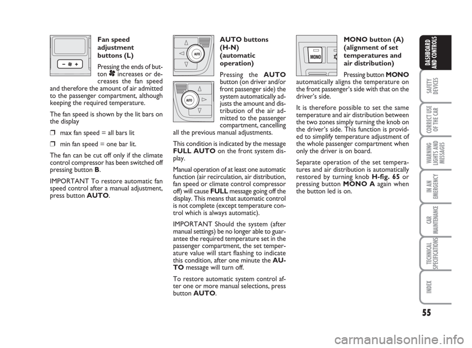
Fan speed
adjustment
buttons (L)
Pressing the ends of but-
ton
pincreases or de-
creases the fan speed
and therefore the amount of air admitted
to the passenger compartment, although
keeping the required temperature.
The fan speed is shown by the lit bars on
the display
❒max fan speed = all bars lit
❒min fan speed = one bar lit.
The fan can be cut off only if the climate
control compressor has been switched off
pressing button B.
IMPORTANT To restore automatic fan
speed control after a manual adjustment,
press button AUTO.AUTO buttons
(H-N)
(automatic
operation)
Pressing the AUTO
button (on driver and/or
front passenger side) the
system automatically ad-
justs the amount and dis-
tribution of the air ad-
mitted to the passenger
compartment, cancelling
all the previous manual adjustments.
This condition is indicated by the message
FULL AUTOon the front system dis-
play.
Manual operation of at least one automatic
function (air recirculation, air distribution,
fan speed or climate control compressor
off) will cause FULLmessage going off the
display. This means that automatic control
is not complete (except temperature con-
trol which is always automatic).
IMPORTANT Should the system (after
manual settings) be no longer able to guar-
antee the required temperature set in the
passenger compartment, the set temper-
ature value will start flashing to indicate
this condition, after one minute the AU-
TOmessage will turn off.
To restore automatic system control af-
ter one or more manual selections, press
button AUTO.MONO button (A)
(alignment of set
temperatures and
air distribution)
Pressing button MONO
automatically aligns the temperature on
the front passenger’s side with that on the
driver’s side.
It is therefore possible to set the same
temperature and air distribution between
the two zones simply turning the knob on
the driver’s side. This function is provid-
ed to simplify temperature adjustment of
the whole passenger compartment when
only the driver is on board.
Separate operation of the set tempera-
tures and air distribution is automatically
restored by turning knob H-fig. 65or
pressing button MONO Aagain when
the button led is on.
036-092 idea GB 1 ed 10-07-2008 16:12 Pagina 55
Page 58 of 210
57
SAFETY
DEVICES
CORRECT USE
OF THE CAR
WARNING
LIGHTS AND
MESSAGES
IN AN
EMERGENCY
CAR
MAINTENANCE
TECHNICAL
SPECIFICATIONS
INDEX
DASHBOARD
AND CONTROLS
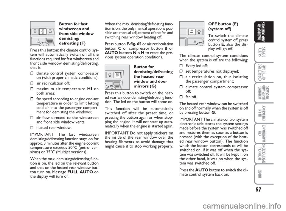
Button for fast
windscreen and
front side window
demisting/
defrosting (F)
Press this button: the climate control sys-
tem will automatically switch on all the
functions required for fast windscreen and
front side window demisting/defrosting,
that is:
❒climate control system compressor
on (with proper climatic conditions);
❒air recirculation off;
❒maximum air temperature HIon
both areas;
❒fan speed according to engine coolant
temperature in order to limit letting
cold air into the passenger compart-
ment for demisting the windows;
❒air flow directed to the windscreen
and front side window vents;
❒heated rear window.
IMPORTANT The fast windscreen
demisting/defrosting function stays on for
approx. 3 minutes after the engine coolant
temperature exceeds 50°C (petrol ver-
sions) or 35°C (Multijet versions).
When the max. demisting/defrosting func-
tion is on, the led on the relevant button
and that on the heated rear window but-
ton turn on. Message FULL AUTOon
the display will turn off.When the max. demisting/defrosting func-
tion is on, the only manual operations pos-
sible are manual adjustment of the fan and
switching rear window heating off.
Press button F-fig. 65or air recirculation
button Cor compressor button Bor
AUTObuttons No Hto reset the pre-
vious system operation conditions.
Button for
demisting/defrosting
the heated rear
window and door
mirrors (G)
Press this button to switch on the heat-
ed rear window demisting/defrosting func-
tion. The led on the button will come on.
This function will be automatically
switched off after the preset time, or
pressing the button again or when stop-
ping the engine. It will not start up auto-
matically when the engine is started again.
IMPORTANT Do not apply stickers on
the inside of the rear window over the
heating filaments to avoid damage that
might cause it to stop working properly.OFF button (E)
(system off)
To switch the climate
control system off, press
button E, also the dis-
play will go off.
The climate control system conditions
when the system is off are the following:
❒Every led off;
❒set temperatures not displayed;
❒air recirculation on, thus isolating
the passenger compartment;
❒climate control system compressor
off;
❒fan off.
The heated rear window can be switched
on and off normally when the system is off
by pressing button G.
IMPORTANT The climate control system
electronic unit stores the system settings
made before the system was switched off
and restores them as soon as a button is
pressed (with the exception of the heat-
ed rear window button). The function
which the button corresponds to will be
switched on, if it was off when the sys-
tem was switched off. It will be kept if, on
the other hand, it was on when the sys-
tem was switched off.
Press the AUTObutton to switch the cli-
mate control system back on.
036-092 idea GB 1 ed 10-07-2008 16:12 Pagina 57
Page 61 of 210
60
SAFETY
DEVICES
CORRECT USE
OF THE CAR
WARNING
LIGHTS AND
MESSAGES
IN AN
EMERGENCY
CAR
MAINTENANCE
TECHNICAL
SPECIFICATIONS
INDEX
DASHBOARD
AND CONTROLS
WINDOW WASHING
WINDSCREEN
WASHER/WIPER
The device can work only when the igni-
tion key is on MAR.
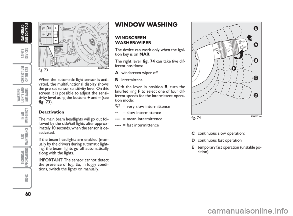
The right lever fig. 74can take five dif-
ferent positions:
Awindscreen wiper off
Bintermittent.
With the lever in position B, turn the
knurled ring Fto select one of four dif-
ferent speeds for the intermittent opera-
tion mode:
,= very slow intermittence
--= slow intermittence
---= mean intermittence
----= fast intermittence
When the automatic light sensor is acti-
vated, the multifunctional display shows
the pre-set sensor sensitivity level. On this
screen it is possible to adjust the sensi-
tivity level using the buttons +and –(see
fig. 73).
Deactivation
The main beam headlights will go out fol-
lowed by the side/tail lights after approx-
imately 10 seconds, when the sensor is de-
activated.
If the beam headlights are enabled (man-
ually by the driver) during automatic light-
ing, the beam lights go off automatically
along with the lights.
IMPORTANT The sensor cannot detect
the presence of fog. So, in foggy condi-
tions, switch the lights on manually.
fig. 73F0H0736m
fig. 74F0H0073m
Ccontinuous slow operation;
Dcontinuous fast operation
Etemporary fast operation (unstable po-
sition).
036-092 idea GB 1 ed 10-07-2008 16:12 Pagina 60
Page 69 of 210
68
SAFETY
DEVICES
CORRECT USE
OF THE CAR
WARNING
LIGHTS AND
MESSAGES
IN AN
EMERGENCY
CAR
MAINTENANCE
TECHNICAL
SPECIFICATIONS
INDEX
DASHBOARD
AND CONTROLS
INTERIOR EQUIPMENT
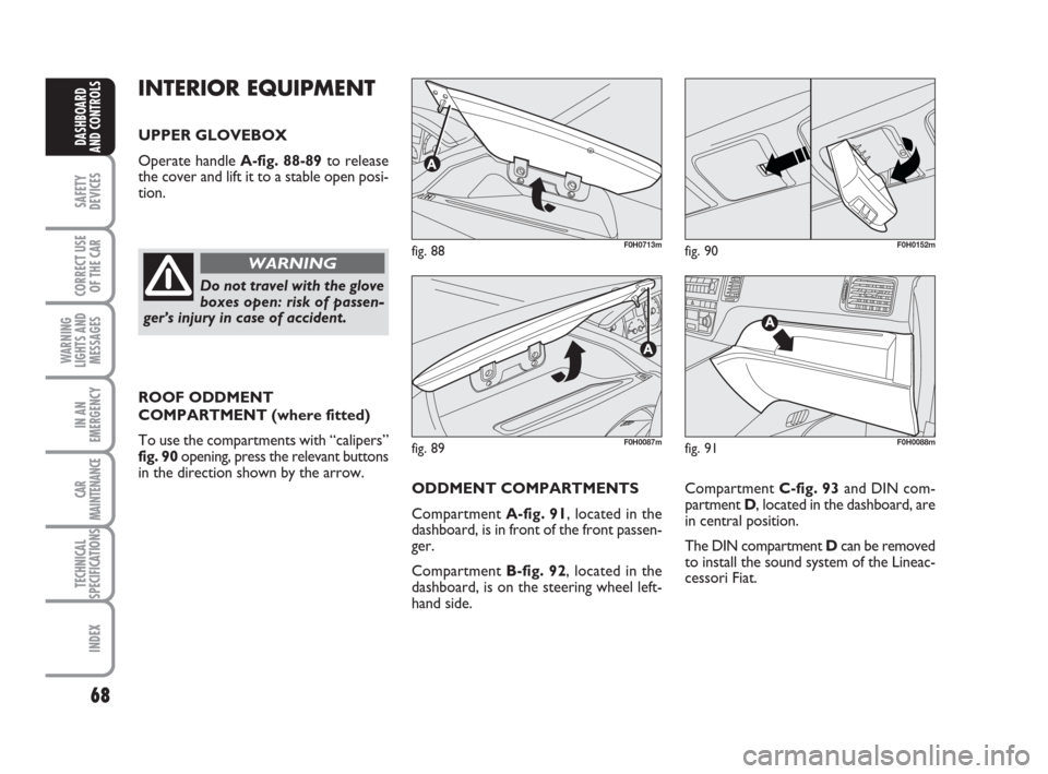
UPPER GLOVEBOX
Operate handle A-fig. 88-89to release
the cover and lift it to a stable open posi-
tion.
ROOF ODDMENT
COMPARTMENT (where fitted)
To use the compartments with “calipers”
fig. 90 opening, press the relevant buttons
in the direction shown by the arrow.
fig. 88F0H0713m
fig. 89F0H0087m
fig. 90F0H0152m
Do not travel with the glove
boxes open: risk of passen-
ger’s injury in case of accident.
WARNING
Compartment C-fig. 93and DIN com-
partment D, located in the dashboard, are
in central position.
The DIN compartment Dcan be removed
to install the sound system of the Lineac-
cessori Fiat.
fig. 91F0H0088m
ODDMENT COMPARTMENTS
Compartment A-fig. 91, located in the
dashboard, is in front of the front passen-
ger.
Compartment B-fig. 92, located in the
dashboard, is on the steering wheel left-
hand side.
036-092 idea GB 1 ed 10-07-2008 16:12 Pagina 68
Page 75 of 210
74
SAFETY
DEVICES
CORRECT USE
OF THE CAR
WARNING
LIGHTS AND
MESSAGES
IN AN
EMERGENCY
CAR
MAINTENANCE
TECHNICAL
SPECIFICATIONS
INDEX
DASHBOARD
AND CONTROLS
POWER WINDOWS
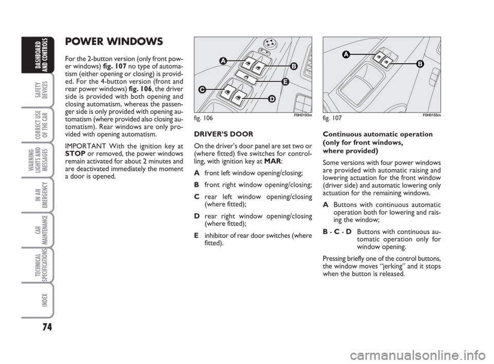
For the 2-button version (only front pow-
er windows) fig. 107no type of automa-
tism (either opening or closing) is provid-
ed. For the 4-button version (front and
rear power windows) fig. 106, the driver
side is provided with both opening and
closing automatism, whereas the passen-
ger side is only provided with opening au-
tomatism (where provided also closing au-
tomatism). Rear windows are only pro-
vided with opening automatism.
IMPORTANT With the ignition key at
STOPor removed, the power windows
remain activated for about 2 minutes and
are deactivated immediately the moment
a door is opened.
fig. 106F0H0103mfig. 107F0H0155m
DRIVER’S DOOR
On the driver’s door panel are set two or
(where fitted) five switches for control-
ling, with ignition key at MAR:
Afront left window opening/closing;
Bfront right window opening/closing;
Crear left window opening/closing
(where fitted);
Drear right window opening/closing
(where fitted);
Einhibitor of rear door switches (where
fitted).Continuous automatic operation
(only for front windows,
where provided)
Some versions with four power windows
are provided with automatic raising and
lowering actuation for the front window
(driver side) and automatic lowering only
actuation for the remaining windows.
AButtons with continuous automatic
operation both for lowering and rais-
ing the window;
B -C -DButtons with continuous au-
tomatic operation only for
window opening.
Pressing briefly one of the control buttons,
the window moves “jerking” and it stops
when the button is released.
036-092 idea GB 1 ed 10-07-2008 16:12 Pagina 74
Page 203 of 210
202
SAFETY
DEVICES
CORRECT USE
OF THE CAR
WARNING
LIGHTS AND
MESSAGES
IN AN
EMERGENCY
CAR
MAINTENANCE
TECHNICAL
SPECIFICATIONS
DASHBOARD
AND CONTROLS
INDEX
In an emergency ........................ 133
Instrument panel ....................... 7
Instruments ................................. 19
Interior equipment ................... 68
Interior fittings
– glass / can holder ................. 69
– magnetic card/ticket slots .. 69
– oddment compartments .... 68
– rear CD compartment
with glass/can holder .......... 70
– roof bracket .......................... 68
– roof console.......................... 70
– upper oddment
compartments ....................... 68
Interiors ...................................... 180
Isofix ............................................. 103
Jack .............................................. 141
Jacking the car ............................ 158
Key kit and door locking ........ 10
Light control buttons ............. 58Load limiters ............................... 97
Lubricants (specifications)........ 196
Magnetic card/ticket slots ...... 69
Main beam headlights
– bulb replacement ................. 147
– control .................................. 58
– flashing .................................... 58
Manual climate control
system ....................................... 48
Multifunction display (on
comfort instrument panel) ... 20
– controls .................................. 21
Multifunction display
(on modal instrument panel) 23
– controls .................................. 23
Number plate light
– bulb replacement ................ 151
Oddment compartments ........ 68
Outlets ......................................... 70
Parking ....................................... 114
Parking sensors .......................... 88
Performance................................ 193
Plates ........................................... 182
Pollen filter ................................. 166
Power windows ......................... 74
Pretensioners.............................. 97
Prolonged car inactivity .......... 122
Protecting the environment .... 92
Radio transmitters and
cellular telephones .................. 86
Rain sensor ................................ 61
Rear fog lights
– bulb replacement ................. 150
– control button ...................... 66
Rear window washer
– control .................................. 62
– fluid level ............................... 171
Rear window wipers
– control .................................. 62
200-208 idea GB 1 ed 13-10-2008 10:54 Pagina 202