technical specifications FIAT IDEA 2012 1.G Owners Manual
[x] Cancel search | Manufacturer: FIAT, Model Year: 2012, Model line: IDEA, Model: FIAT IDEA 2012 1.GPages: 210, PDF Size: 3.65 MB
Page 135 of 210
134
CAR
MAINTENANCE
TECHNICAL
SPECIFICATIONS
INDEX
DASHBOARD
AND CONTROLS
SAFETY
DEVICES
CORRECT USE
OF THE CAR
WARNING
LIGHTS AND
MESSAGES
IN AN
EMERGENCY
DOOR
OPENING/CLOSING
Emergency door locking device
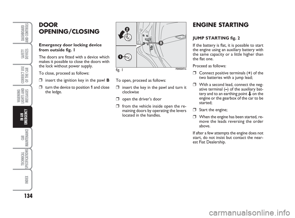
from outside fig. 1
The doors are fitted with a device which
makes it possible to close the doors with
the lock without power supply.
To close, proceed as follows:
❒insert the ignition key in the pawl B
❒turn the device to position 1and close
the ledge.To open, proceed as follows:❒insert the key in the pawl and turn it
clockwise
❒open the driver’s door
❒from the vehicle inside open the re-
maining doors by operating the levers
located in the handles.
fig. 1F0H0247m
ENGINE STARTING
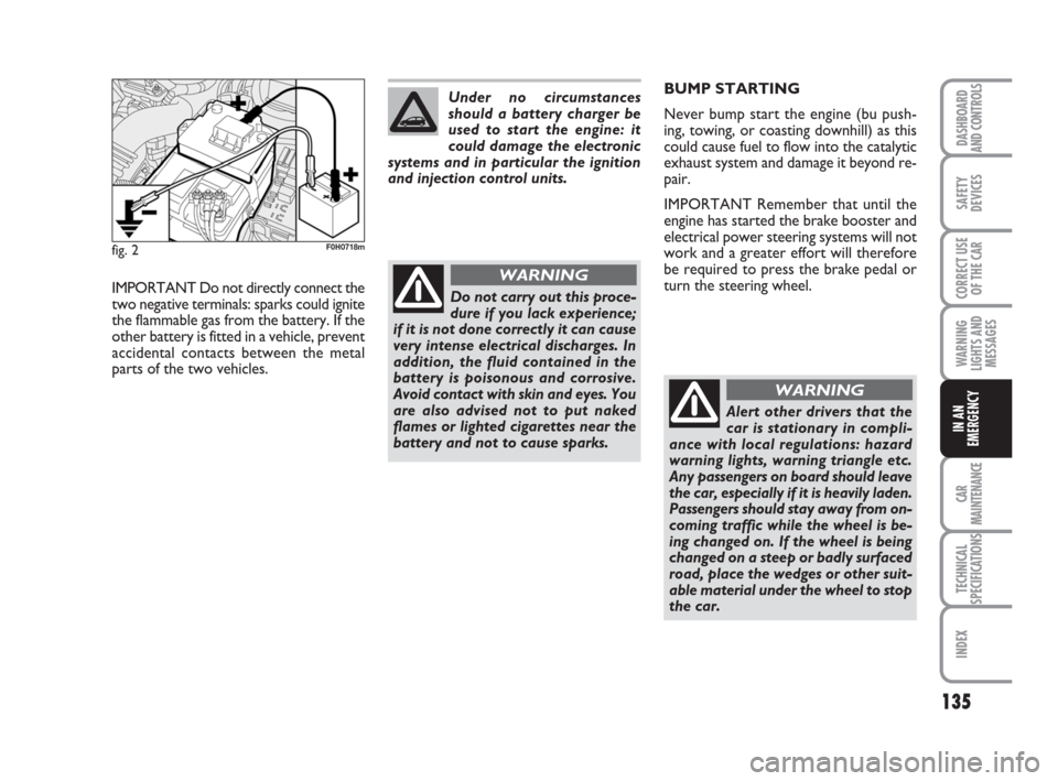
JUMP STARTING fig. 2
If the battery is flat, it is possible to start
the engine using an auxiliary battery with
the same capacity or a little higher than
the flat one.
Proceed as follows:
❒Connect positive terminals (+) of the
two batteries with a jump lead;
❒With a second lead, connect the neg-
ative terminal (–) of the auxiliary bat-
tery and to an earthing point
Eon the
engine or the gearbox of the car to be
started;
❒Start the engine;
❒When the engine has been started, re-
move the leads reversing the order
above.
If after a few attempts the engine does not
start, do not insist but contact the near-
est Fiat Dealership.
133-160 idea GB 1 ed 10-07-2008 8:30 Pagina 134
Page 136 of 210
135
CAR
MAINTENANCE
TECHNICAL
SPECIFICATIONS
INDEX
DASHBOARD
AND CONTROLS
SAFETY
DEVICES
CORRECT USE
OF THE CAR
WARNING
LIGHTS AND
MESSAGES
IN AN
EMERGENCY
fig. 2F0H0718m
IMPORTANT Do not directly connect the
two negative terminals: sparks could ignite
the flammable gas from the battery. If the
other battery is fitted in a vehicle, prevent
accidental contacts between the metal
parts of the two vehicles.Do not carry out this proce-
dure if you lack experience;
if it is not done correctly it can cause
very intense electrical discharges. In
addition, the fluid contained in the
battery is poisonous and corrosive.
Avoid contact with skin and eyes. You
are also advised not to put naked
flames or lighted cigarettes near the
battery and not to cause sparks.
WARNING
Under no circumstances
should a battery charger be
used to start the engine: it
could damage the electronic
systems and in particular the ignition
and injection control units.BUMP STARTING
Never bump start the engine (bu push-
ing, towing, or coasting downhill) as this
could cause fuel to flow into the catalytic
exhaust system and damage it beyond re-
pair.
IMPORTANT Remember that until the
engine has started the brake booster and
electrical power steering systems will not
work and a greater effort will therefore
be required to press the brake pedal or
turn the steering wheel.
Alert other drivers that the
car is stationary in compli-
ance with local regulations: hazard
warning lights, warning triangle etc.
Any passengers on board should leave
the car, especially if it is heavily laden.
Passengers should stay away from on-
coming traffic while the wheel is be-
ing changed on. If the wheel is being
changed on a steep or badly surfaced
road, place the wedges or other suit-
able material under the wheel to stop
the car.
WARNING
133-160 idea GB 1 ed 10-07-2008 8:30 Pagina 135
Page 137 of 210
136
CAR
MAINTENANCE
TECHNICAL
SPECIFICATIONS
INDEX
DASHBOARD
AND CONTROLS
SAFETY
DEVICES
CORRECT USE
OF THE CAR
WARNING
LIGHTS AND
MESSAGES
IN AN
EMERGENCY
FIX & GO automatic
(QUICK TYRE REPAIR
KIT) (where provided)
The quick tyre repair kit Fix & Go auto-
matic is placed in the boot.
The kit includes:
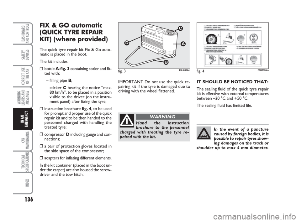
❒bottle A-fig. 3containing sealer and fit-
ted with:
– filling pipe B;
– sticker Cbearing the notice “max.
80 km/h”, to be placed in a position
visible to the driver (on the instru-
ment panel) after fixing the tyre;
❒instruction brochure fig. 4, to be used
for prompt and proper use of the quick
repair kit and to be then handed to the
personnel charged with handling the
treated tyre;
❒compressor Dincluding gauge and con-
nections;
❒a pair of protection gloves located in
the side space of the compressor;
❒adapters for inflating different elements.
In the kit container (placed in the boot un-
der the carpet) are also housed the screw-
driver and the tow hitch.IMPORTANT Do not use the quick re-
pairing kit if the tyre is damaged due to
driving with the wheel flattened.
fig. 3F0H0354mfig. 4F0H0355m
Hand the instruction
brochure to the personnel
charged with treating the tyre re-
paired with the kit.
WARNING
IT SHOULD BE NOTICED THAT:
The sealing fluid of the quick tyre repair
kit is effective with external temperatures
between –20 °C and +50 °C.
The sealing fluid has limited life.
In the event of a puncture
caused by foreign bodies, it is
possible to repair tyres show-
ing damages on the track or
shoulder up to max 4 mm diameter.
133-160 idea GB 1 ed 10-07-2008 8:30 Pagina 136
Page 138 of 210
137
CAR
MAINTENANCE
TECHNICAL
SPECIFICATIONS
INDEX
DASHBOARD
AND CONTROLS
SAFETY
DEVICES
CORRECT USE
OF THE CAR
WARNING
LIGHTS AND
MESSAGES
IN AN
EMERGENCY
Holes and damages on the
tyre side walls cannot be re-
paired. Do not use the quick tyre re-
pair kit if damaging is due to running
with flat tyre.
WARNING
Repairs are not possible in
case of damages on the
wheel rim (bad groove distortion
causing air loss). Do not remove for-
eign bodies (screws or nails) from the
tyre.
WARNING
The compressor shall not be
operated for more than 20
minutes. Risk of overheating!. Tyres
repaired with the quick tyre repair kit
shall be used temporarily only.
WARNING
INFLATING PROCEDURE
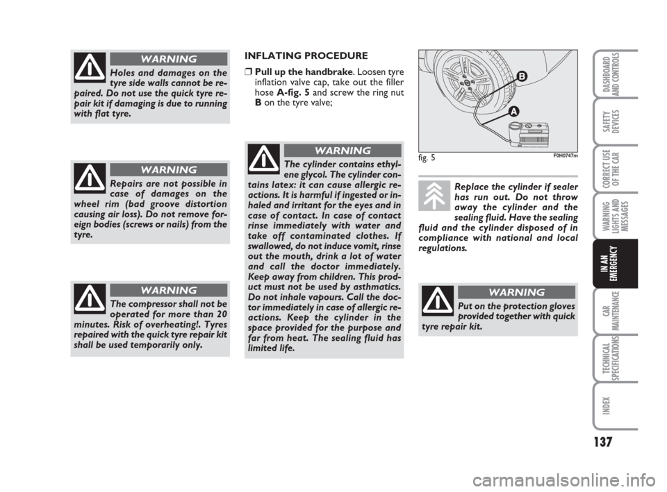
❒Pull up the handbrake. Loosen tyre
inflation valve cap, take out the filler
hose A-fig. 5and screw the ring nut
Bon the tyre valve;
fig. 5F0H0747mThe cylinder contains ethyl-
ene glycol. The cylinder con-
tains latex: it can cause allergic re-
actions. It is harmful if ingested or in-
haled and irritant for the eyes and in
case of contact. In case of contact
rinse immediately with water and
take off contaminated clothes. If
swallowed, do not induce vomit, rinse
out the mouth, drink a lot of water
and call the doctor immediately.
Keep away from children. This prod-
uct must not be used by asthmatics.
Do not inhale vapours. Call the doc-
tor immediately in case of allergic re-
actions. Keep the cylinder in the
space provided for the purpose and
far from heat. The sealing fluid has
limited life.
WARNING
Replace the cylinder if sealer
has run out. Do not throw
away the cylinder and the
sealing fluid. Have the sealing
fluid and the cylinder disposed of in
compliance with national and local
regulations.
Put on the protection gloves
provided together with quick
tyre repair kit.
WARNING
133-160 idea GB 1 ed 10-07-2008 8:30 Pagina 137
Page 139 of 210
138
CAR
MAINTENANCE
TECHNICAL
SPECIFICATIONS
INDEX
DASHBOARD
AND CONTROLS
SAFETY
DEVICES
CORRECT USE
OF THE CAR
WARNING
LIGHTS AND
MESSAGES
IN AN
EMERGENCY
fig. 6F0H0357mfig. 7F0H0177mfig. 8F0H0748m
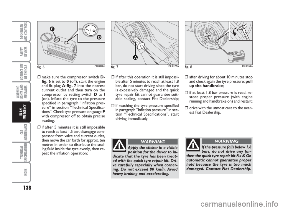
❒make sure the compressor switch D-
fig. 6is set to 0(off), start the engine
and fit plug A-fig. 7into the nearest
current outlet and then turn on the
compressor by setting switch Dto I
(on). Inflate the tyre to the pressure
specified in paragraph “Inflation pres-
sure” in section “Technical Specifica-
tions”. Check tyre pressure on gauge F
with compressor off to obtain precise
reading;
❒if after 5 minutes it is still impossible
to reach at least 1.5 bar, disengage com-
pressor from valve and current outlet,
then move the car forth for approx. ten
metres in order to distribute the seal-
ing fluid inside the tyre evenly, then re-
peat the inflation operation;
❒If after this operation it is still impossi-
ble after 5 minutes to reach at least 1.8
bar, do not start driving since the tyre
is excessively damaged and the quick
tyre repair kit cannot guarantee suit-
able sealing, contact Fiat Dealership;
❒if reaching the tyre pressure specified
in paragraph “Inflation pressure” in sec-
tion “Technical Specifications”, start
driving immediately;
Apply the sticker in a visible
position for the driver to in-
dicate that the tyre has been treat-
ed with the quick tyre repair kit. Dri-
ve carefully especially when corner-
ing. Do not exceed 80 km/h. Avoid
heavy braking and accelerating.
WARNING
If the pressure falls below 1.8
bars, do not drive any fur-
ther: the quick tyre repair kit Fix & Go
automatic cannot guarantee proper
hold because the tyre is too much
damaged. Contact Fiat Dealership.
WARNING
❒after driving for about 10 minutes stop
and check again the tyre pressure; pull
up the handbrake;
❒if at least 1.8 bar pressure is read, re-
store proper pressure (with engine
running and handbrake on) and restart;
❒drive with the utmost care to the near-
est Fiat Dealership.
133-160 idea GB 1 ed 10-07-2008 8:30 Pagina 138
Page 140 of 210
139
CAR
MAINTENANCE
TECHNICAL
SPECIFICATIONS
INDEX
DASHBOARD
AND CONTROLS
SAFETY
DEVICES
CORRECT USE
OF THE CAR
WARNING
LIGHTS AND
MESSAGES
IN AN
EMERGENCY
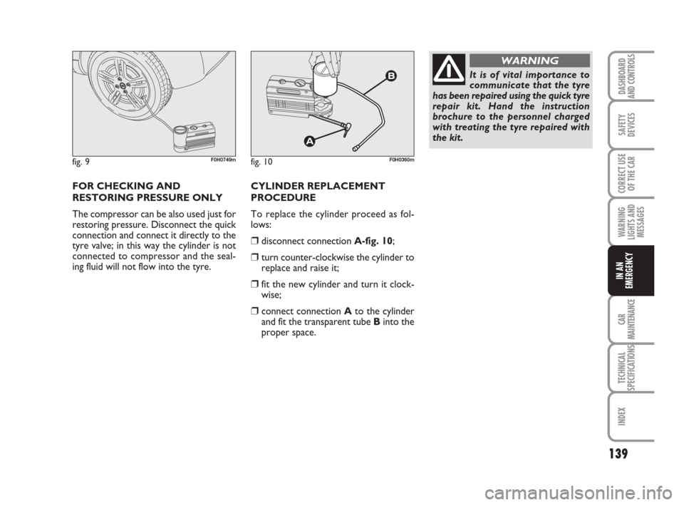
fig. 9F0H0749m
FOR CHECKING AND
RESTORING PRESSURE ONLY
The compressor can be also used just for
restoring pressure. Disconnect the quick
connection and connect it directly to the
tyre valve; in this way the cylinder is not
connected to compressor and the seal-
ing fluid will not flow into the tyre.
fig. 10F0H0360m
CYLINDER REPLACEMENT
PROCEDURE
To replace the cylinder proceed as fol-
lows:
❒disconnect connection A-fig. 10;
❒turn counter-clockwise the cylinder to
replace and raise it;
❒fit the new cylinder and turn it clock-
wise;
❒connect connection Ato the cylinder
and fit the transparent tube Binto the
proper space.
It is of vital importance to
communicate that the tyre
has been repaired using the quick tyre
repair kit. Hand the instruction
brochure to the personnel charged
with treating the tyre repaired with
the kit.
WARNING
133-160 idea GB 1 ed 10-07-2008 8:30 Pagina 139
Page 141 of 210
140
CAR
MAINTENANCE
TECHNICAL
SPECIFICATIONS
INDEX
DASHBOARD
AND CONTROLS
SAFETY
DEVICES
CORRECT USE
OF THE CAR
WARNING
LIGHTS AND
MESSAGES
IN AN
EMERGENCY
IF A TYRE IS
PUNCTURED
GENERAL INSTRUCTIONS
Wheel changing and correct use of the
jack and space-saver spare wheel call for
some precautions as listed below.
WARNING If the car is equipped with
“Kit for tyre quick repair Fix & Go”, see
the instructions contained in the follow-
ing chapter.
The space-saver spare wheel
is specific to the vehicle: do
not use it on other models and do not
use spare wheels designed for other
models on your car. The space-saver
spare wheel must only be used in the
event of an emergency, and then on-
ly for as little as possible and at no
more than 80 km/h. The space-saver
spare wheel is fitted with an orange
sticker giving the main instructions for
its use and limitations. The sticker
must never be removed or covered.
Do not fit the hub cap to the spare
wheel. The sticker gives the following
information in four languages: C
AU-TION! FOR TEMPORARY USE ONLY! 80KM/H MAX! REPLACE BY NORMAL WHEEL
AS SOON AS POSSIBLE. DO NOT COVER THIS
LABEL IN USE.
WARNING
When driving with a space-
saver spare wheel fitted, the
driving performance of your car may
change. Avoid accelerating or brak-
ing suddenly, steering abruptly or fast
cornering. The lifespan of a space-
saver spare wheel is approximately
3000 km, after which it will need to
be replaced with another spare wheel
of the same type. Never fit a standard
tyre on the space-saver spare wheel
rim. Have the wheel replaced and re-
fitted as soon as possible. Never use
two or more spare wheels at the same
time. Do not lubricate the bolt
threads before fitting them back: they
could come loose.
WARNING
133-160 idea GB 1 ed 10-07-2008 8:30 Pagina 140
Page 142 of 210
141
CAR
MAINTENANCE
TECHNICAL
SPECIFICATIONS
INDEX
DASHBOARD
AND CONTROLS
SAFETY
DEVICES
CORRECT USE
OF THE CAR
WARNING
LIGHTS AND
MESSAGES
IN AN
EMERGENCY
The jack should only be used
to change a wheel on the car
for which it was designed. It should
not be put to other uses or employed
to raise other models of cars. Under
no circumstances should it be used
when carrying out repairs under the
car. An incorrectly positioned jack
may cause the car to fall. Do not use
the jack to lift loads exceeding that
indicated on the label attached to the
jack itself. Do not fit snow chains on
a space-saver spare wheel. If a front
wheel (drive wheel) is punctured and
you require snow chains to proceed,
take a standard wheel from the rear
axle and fit the space-saver spare
wheel in its place. Having fitted two
standard wheels on the front drive
axle you can use snow chains, thus
solving the emergency situation.
WARNING
Fasten the wheel cap cor-
rectly to prevent the wheel
from coming free in motion. Never
tamper with the inflation valve. Nev-
er place tools between the rim and
tyre. Check the tyre and space-saver
spare wheel pressure regularly. The
tyre inflation pressure is shown in the
“Technical specifications” chapter.
WARNINGPlease note:
❒the jack cannot be repaired. If it breaks
it must be replaced with a new jack;
❒no tool other than its cranking device
may be fitted on the jack.
To change a wheel proceed as follows:
❒Stop the car in a position that is not
dangerous for oncoming traffic where
you can change the wheel safely. The
ground should be flat and adequately
firm;
❒Turn the engine off and pull up the
handbrake;
❒Engage first gear or reverse;
❒Lift the luggage compartment panel
mat;
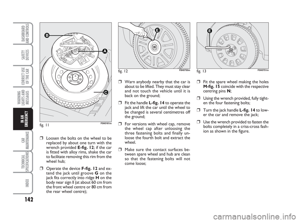
❒Loosen the fastener A-fig. 11;
❒Take the tool bag Band go to the
wheel to be replaced;
❒Take the space-saver spare wheel C;
❒If the car is fitted with alloy rims, re-
move the wheel hub with the screw-
driver provided levering in the groove
E-fig. 12, as shown in the figure;
133-160 idea GB 1 ed 10-07-2008 8:30 Pagina 141
Page 143 of 210
142
CAR
MAINTENANCE
TECHNICAL
SPECIFICATIONS
INDEX
DASHBOARD
AND CONTROLS
SAFETY
DEVICES
CORRECT USE
OF THE CAR
WARNING
LIGHTS AND
MESSAGES
IN AN
EMERGENCY
❒Loosen the bolts on the wheel to be
replaced by about one turn with the
wrench provided E-fig. 12; if the car
is fitted with alloy rims, shake the car
to facilitate removing this rim from the
wheel hub;
❒Operate the device F-fig. 12and ex-
tend the jack until groove Gon the
jack fits correctly into ridge Hon the
body near sign I(at about 60 cm from
the front wheel centre or 80 cm from
the rear wheel centre);
fig. 12F0H0750m
❒Warn anybody nearby that the car is
about to be lifted. They must stay clear
and not touch the vehicle until it is
back on the ground;
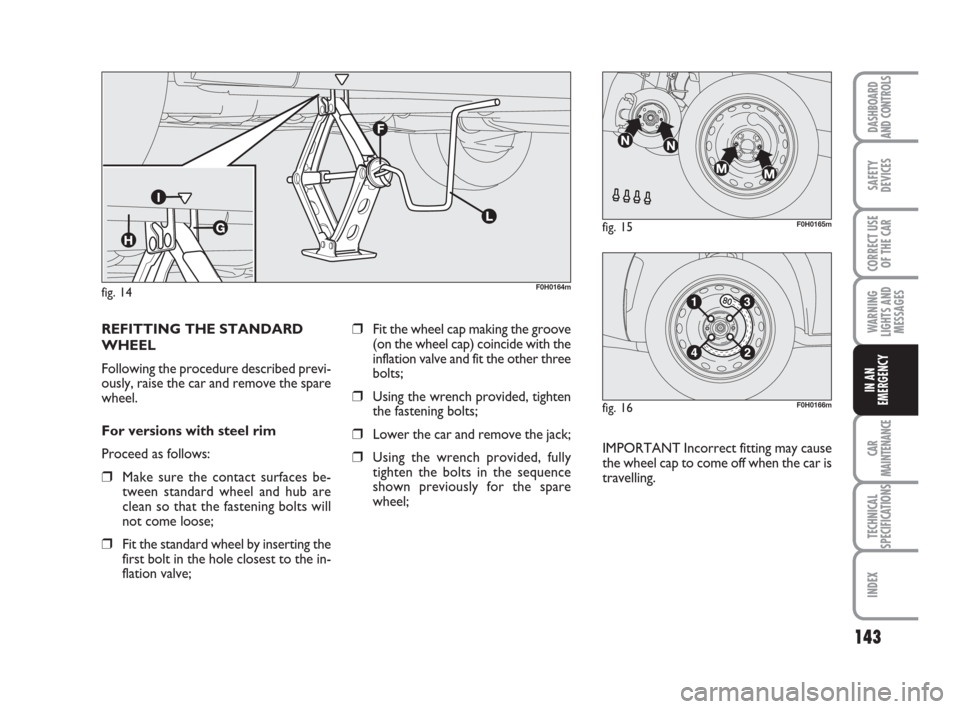
❒Fit the handle L-fig. 14to operate the
jack and lift the car until the wheel to
be changed is several centimetres off
the ground;
❒For versions with wheel cap, remove
the wheel cap after unloosing the
three fastening bolts and finally un-
loose the fourth bolt and extract the
wheel.
❒Make sure the contact surfaces be-
tween spare wheel and hub are clean
so that the fastening bolts will not
come loose;
fig. 13F0H0751m
❒Fit the spare wheel making the holes
M-fig. 15coincide with the respective
centring pins N;
❒Using the wrench provided, fully tight-
en the four fastening bolts;
❒Turn the jack handle L-fig. 14to low-
er the car and remove the jack;
❒Use the wrench provided to fasten the
bolts completely in a criss-cross fash-
ion as shown in the figure.fig. 11F0H0161m
133-160 idea GB 1 ed 10-07-2008 8:30 Pagina 142
Page 144 of 210
143
CAR
MAINTENANCE
TECHNICAL
SPECIFICATIONS
INDEX
DASHBOARD
AND CONTROLS
SAFETY
DEVICES
CORRECT USE
OF THE CAR
WARNING
LIGHTS AND
MESSAGES
IN AN
EMERGENCY
fig. 14F0H0164m
fig. 15F0H0165m
fig. 16F0H0166m
REFITTING THE STANDARD
WHEEL
Following the procedure described previ-
ously, raise the car and remove the spare
wheel.
For versions with steel rim
Proceed as follows:
❒Make sure the contact surfaces be-
tween standard wheel and hub are
clean so that the fastening bolts will
not come loose;
❒Fit the standard wheel by inserting the
first bolt in the hole closest to the in-
flation valve;
❒Fit the wheel cap making the groove
(on the wheel cap) coincide with the
inflation valve and fit the other three
bolts;
❒Using the wrench provided, tighten
the fastening bolts;
❒Lower the car and remove the jack;
❒Using the wrench provided, fully
tighten the bolts in the sequence
shown previously for the spare
wheel;IMPORTANT Incorrect fitting may cause
the wheel cap to come off when the car is
travelling.
133-160 idea GB 1 ed 10-07-2008 8:30 Pagina 143