technical specifications FIAT IDEA 2012 1.G Workshop Manual
[x] Cancel search | Manufacturer: FIAT, Model Year: 2012, Model line: IDEA, Model: FIAT IDEA 2012 1.GPages: 210, PDF Size: 3.65 MB
Page 55 of 210
54
SAFETY
DEVICES
CORRECT USE
OF THE CAR
WARNING
LIGHTS AND
MESSAGES
IN AN
EMERGENCY
CAR
MAINTENANCE
TECHNICAL
SPECIFICATIONS
INDEX
DASHBOARD
AND CONTROLS
More particularly, max. fan speed will not
be immediately engaged if coolant is not
hot enough; this to prevent admitting air
that is not warm enough to the passenger
compartment.
All manual settings are however possible
with this function on.
To switch the function off, simply turn the
temperature knob counterclockwise and
set the required temperature.
❒LOfunction (highest cooling power):
this is activated by turning the tempera-
ture knob counterclockwise below the
min. value (16 °C). It can be activated in-
dependently from the driver’s or passen-
ger’s side or both (also selecting the
MONOfunction).
This function can be engaged when re-
quiring to cool the passenger compart-
ment as quickly as possible, exploiting the
maximum potential of the system. This
function engages inside air recirculation
and climate control compressor, while air
distribution and fan speed are controlled
according to environmental conditions. All manual settings are however possible
with this function on.
To switch the function off, simply turn the
temperature knob clockwise and set the
required temperature.
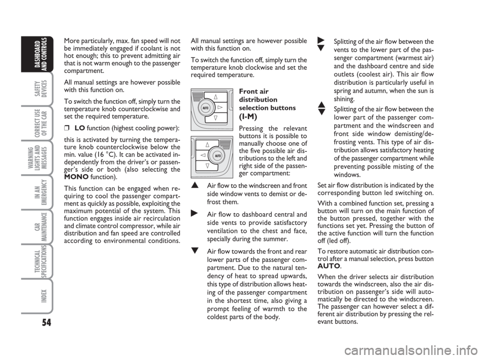
Front air
distribution
selection buttons
(I-M)
Pressing the relevant
buttons it is possible to
manually choose one of
the five possible air dis-
tributions to the left and
right side of the passen-
ger compartment:
▲Air flow to the windscreen and front
side window vents to demist or de-
frost them.
˙Air flow to dashboard central and
side vents to provide satisfactory
ventilation to the chest and face,
specially during the summer.
▼Air flow towards the front and rear
lower parts of the passenger com-
partment. Due to the natural ten-
dency of heat to spread upwards,
this type of distribution allows heat-
ing of the passenger compartment
in the shortest time, also giving a
prompt feeling of warmth to the
coldest parts of the body.
˙
▼Splitting of the air flow between the
vents to the lower part of the pas-
senger compartment (warmest air)
and the dashboard centre and side
outlets (coolest air). This air flow
distribution is particularly useful in
spring and autumn, when the sun is
shining.
▲
▼Splitting of the air flow between the
lower part of the passenger com-
partment and the windscreen and
front side window demisting/de-
frosting vents. This type of air dis-
tribution allows satisfactory heating
of the passenger compartment while
preventing possible misting of the
windows.
Set air flow distribution is indicated by the
corresponding button led switching on.
With a combined function set, pressing a
button will turn on the main function of
the button pressed, together with the
functions set yet. Pressing the button of
the active function will turn the function
off (led off).
To restore automatic air distribution con-
trol after a manual selection, press button
AUTO.
When the driver selects air distribution
towards the windscreen, also the air dis-
tribution on passenger’s side will auto-
matically be directed to the windscreen.
The passenger can however select a dif-
ferent air distribution by pressing the rel-
evant buttons.
036-092 idea GB 1 ed 10-07-2008 16:12 Pagina 54
Page 56 of 210
55
SAFETY
DEVICES
CORRECT USE
OF THE CAR
WARNING
LIGHTS AND
MESSAGES
IN AN
EMERGENCY
CAR
MAINTENANCE
TECHNICAL
SPECIFICATIONS
INDEX
DASHBOARD
AND CONTROLS
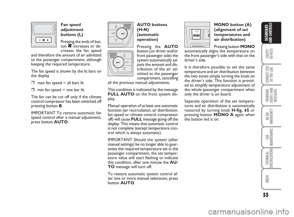
Fan speed
adjustment
buttons (L)
Pressing the ends of but-
ton
pincreases or de-
creases the fan speed
and therefore the amount of air admitted
to the passenger compartment, although
keeping the required temperature.
The fan speed is shown by the lit bars on
the display
❒max fan speed = all bars lit
❒min fan speed = one bar lit.
The fan can be cut off only if the climate
control compressor has been switched off
pressing button B.
IMPORTANT To restore automatic fan
speed control after a manual adjustment,
press button AUTO.AUTO buttons
(H-N)
(automatic
operation)
Pressing the AUTO
button (on driver and/or
front passenger side) the
system automatically ad-
justs the amount and dis-
tribution of the air ad-
mitted to the passenger
compartment, cancelling
all the previous manual adjustments.
This condition is indicated by the message
FULL AUTOon the front system dis-
play.
Manual operation of at least one automatic
function (air recirculation, air distribution,
fan speed or climate control compressor
off) will cause FULLmessage going off the
display. This means that automatic control
is not complete (except temperature con-
trol which is always automatic).
IMPORTANT Should the system (after
manual settings) be no longer able to guar-
antee the required temperature set in the
passenger compartment, the set temper-
ature value will start flashing to indicate
this condition, after one minute the AU-
TOmessage will turn off.
To restore automatic system control af-
ter one or more manual selections, press
button AUTO.MONO button (A)
(alignment of set
temperatures and
air distribution)
Pressing button MONO
automatically aligns the temperature on
the front passenger’s side with that on the
driver’s side.
It is therefore possible to set the same
temperature and air distribution between
the two zones simply turning the knob on
the driver’s side. This function is provid-
ed to simplify temperature adjustment of
the whole passenger compartment when
only the driver is on board.
Separate operation of the set tempera-
tures and air distribution is automatically
restored by turning knob H-fig. 65or
pressing button MONO Aagain when
the button led is on.
036-092 idea GB 1 ed 10-07-2008 16:12 Pagina 55
Page 57 of 210
56
SAFETY
DEVICES
CORRECT USE
OF THE CAR
WARNING
LIGHTS AND
MESSAGES
IN AN
EMERGENCY
CAR
MAINTENANCE
TECHNICAL
SPECIFICATIONS
INDEX
DASHBOARD
AND CONTROLS
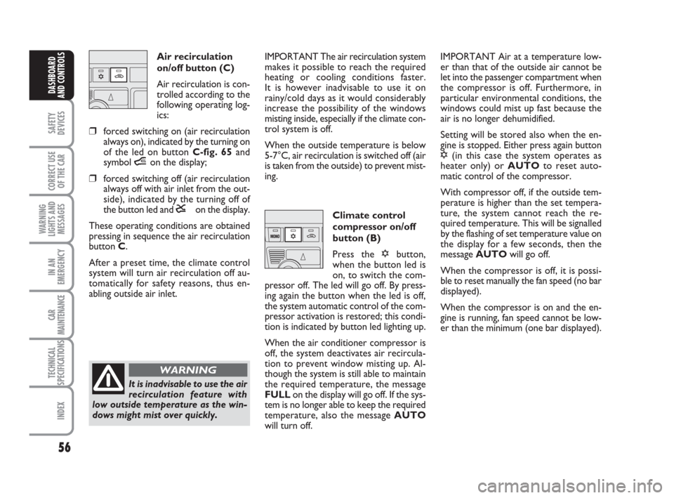
Air recirculation
on/off button (C)
Air recirculation is con-
trolled according to the
following operating log-
ics:
❒forced switching on (air recirculation
always on), indicated by the turning on
of the led on button C-fig. 65and
symbol íon the display;
❒forced switching off (air recirculation
always off with air inlet from the out-
side), indicated by the turning off of
the button led and êon the display.
These operating conditions are obtained
pressing in sequence the air recirculation
button C.
After a preset time, the climate control
system will turn air recirculation off au-
tomatically for safety reasons, thus en-
abling outside air inlet.IMPORTANT The air recirculation system
makes it possible to reach the required
heating or cooling conditions faster.
It is however inadvisable to use it on
rainy/cold days as it would considerably
increase the possibility of the windows
misting inside, especially if the climate con-
trol system is off.
When the outside temperature is below
5-7°C, air recirculation is switched off (air
is taken from the outside) to prevent mist-
ing.
Climate control
compressor on/off
button (B)
Press the √button,
when the button led is
on, to switch the com-
pressor off. The led will go off. By press-
ing again the button when the led is off,
the system automatic control of the com-
pressor activation is restored; this condi-
tion is indicated by button led lighting up.
When the air conditioner compressor is
off, the system deactivates air recircula-
tion to prevent window misting up. Al-
though the system is still able to maintain
the required temperature, the message
FULLon the display will go off. If the sys-
tem is no longer able to keep the required
temperature, also the message AUTO
will turn off.IMPORTANT Air at a temperature low-
er than that of the outside air cannot be
let into the passenger compartment when
the compressor is off. Furthermore, in
particular environmental conditions, the
windows could mist up fast because the
air is no longer dehumidified.
Setting will be stored also when the en-
gine is stopped. Either press again button
√(in this case the system operates as
heater only) or AUTOto reset auto-
matic control of the compressor.
With compressor off, if the outside tem-
perature is higher than the set tempera-
ture, the system cannot reach the re-
quired temperature. This will be signalled
by the flashing of set temperature value on
the display for a few seconds, then the
message AUTOwill go off.
When the compressor is off, it is possi-
ble to reset manually the fan speed (no bar
displayed).
When the compressor is on and the en-
gine is running, fan speed cannot be low-
er than the minimum (one bar displayed).
It is inadvisable to use the air
recirculation feature with
low outside temperature as the win-
dows might mist over quickly.
WARNING
036-092 idea GB 1 ed 10-07-2008 16:12 Pagina 56
Page 58 of 210
57
SAFETY
DEVICES
CORRECT USE
OF THE CAR
WARNING
LIGHTS AND
MESSAGES
IN AN
EMERGENCY
CAR
MAINTENANCE
TECHNICAL
SPECIFICATIONS
INDEX
DASHBOARD
AND CONTROLS
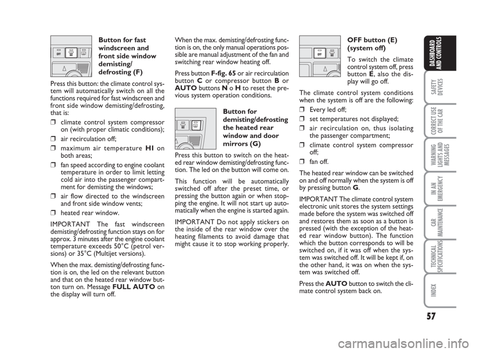
Button for fast
windscreen and
front side window
demisting/
defrosting (F)
Press this button: the climate control sys-
tem will automatically switch on all the
functions required for fast windscreen and
front side window demisting/defrosting,
that is:
❒climate control system compressor
on (with proper climatic conditions);
❒air recirculation off;
❒maximum air temperature HIon
both areas;
❒fan speed according to engine coolant
temperature in order to limit letting
cold air into the passenger compart-
ment for demisting the windows;
❒air flow directed to the windscreen
and front side window vents;
❒heated rear window.
IMPORTANT The fast windscreen
demisting/defrosting function stays on for
approx. 3 minutes after the engine coolant
temperature exceeds 50°C (petrol ver-
sions) or 35°C (Multijet versions).
When the max. demisting/defrosting func-
tion is on, the led on the relevant button
and that on the heated rear window but-
ton turn on. Message FULL AUTOon
the display will turn off.When the max. demisting/defrosting func-
tion is on, the only manual operations pos-
sible are manual adjustment of the fan and
switching rear window heating off.
Press button F-fig. 65or air recirculation
button Cor compressor button Bor
AUTObuttons No Hto reset the pre-
vious system operation conditions.
Button for
demisting/defrosting
the heated rear
window and door
mirrors (G)
Press this button to switch on the heat-
ed rear window demisting/defrosting func-
tion. The led on the button will come on.
This function will be automatically
switched off after the preset time, or
pressing the button again or when stop-
ping the engine. It will not start up auto-
matically when the engine is started again.
IMPORTANT Do not apply stickers on
the inside of the rear window over the
heating filaments to avoid damage that
might cause it to stop working properly.OFF button (E)
(system off)
To switch the climate
control system off, press
button E, also the dis-
play will go off.
The climate control system conditions
when the system is off are the following:
❒Every led off;
❒set temperatures not displayed;
❒air recirculation on, thus isolating
the passenger compartment;
❒climate control system compressor
off;
❒fan off.
The heated rear window can be switched
on and off normally when the system is off
by pressing button G.
IMPORTANT The climate control system
electronic unit stores the system settings
made before the system was switched off
and restores them as soon as a button is
pressed (with the exception of the heat-
ed rear window button). The function
which the button corresponds to will be
switched on, if it was off when the sys-
tem was switched off. It will be kept if, on
the other hand, it was on when the sys-
tem was switched off.
Press the AUTObutton to switch the cli-
mate control system back on.
036-092 idea GB 1 ed 10-07-2008 16:12 Pagina 57
Page 59 of 210
58
SAFETY
DEVICES
CORRECT USE
OF THE CAR
WARNING
LIGHTS AND
MESSAGES
IN AN
EMERGENCY
CAR
MAINTENANCE
TECHNICAL
SPECIFICATIONS
INDEX
DASHBOARD
AND CONTROLS
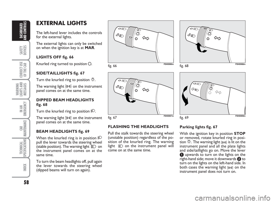
EXTERNAL LIGHTS
The left-hand lever includes the controls
for the external lights.
The external lights can only be switched
on when the ignition key is at MAR.
LIGHTS OFF fig. 66
Knurled ring turned to position
å.
SIDE/TAILLIGHTS fig. 67
Turn the knurled ring to position
6.
The warning light
3on the instrument
panel comes on at the same time.
DIPPED BEAM HEADLIGHTS
fig. 68
Turn the knurled ring to position 2.
The warning light
3on the instrument
panel comes on at the same time.
BEAM HEADLIGHTS fig. 69
When the knurled ring is in position 2
pull the lever towards the steering wheel
(stable position). The warning light
1on
the instrument panel comes on at the
same time.
To turn the beam headlights off, pull again
the lever towards the steering wheel
(dipped beams will turn on again).FLASHING THE HEADLIGHTS
Pull the stalk towards the steering wheel
(unstable position) regardless of the po-
sition of the knurled ring. The warning
light
1on the instrument panel will
come on at the same time.Parking lights fig. 67
With the ignition key in position STOP
or removed, rotate knurled ring in posi-
tion 6. The warning light 3is lit on the
instrument panel and all the plate lights
and side/taillights go on. Move the lever
aupwards to turn on the lights on the
right-hand side; move it downwards bto
turn on the lights on the left-hand side. In
both cases the warning light
3on the
instrument panel does not turn on.
fig. 66F0H0066m
fig. 69F0H0069m
fig. 68F0H0068m
fig. 67F0H0067m
036-092 idea GB 1 ed 10-07-2008 16:12 Pagina 58
Page 60 of 210
59
SAFETY
DEVICES
CORRECT USE
OF THE CAR
WARNING
LIGHTS AND
MESSAGES
IN AN
EMERGENCY
CAR
MAINTENANCE
TECHNICAL
SPECIFICATIONS
INDEX
DASHBOARD
AND CONTROLS
fig. 70F0H0071mfig. 71F0H0070mfig. 72F0H0072m
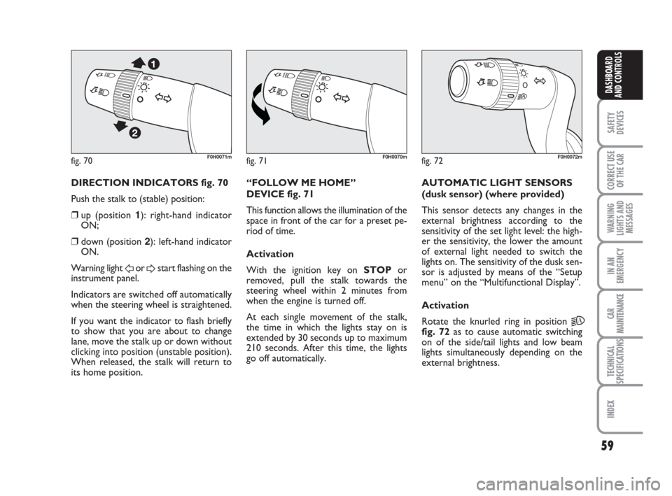
DIRECTION INDICATORS fig. 70
Push the stalk to (stable) position:
❒up (position 1): right-hand indicator
ON;
❒down (position 2): left-hand indicator
ON.
Warning light
For Dstart flashing on the
instrument panel.
Indicators are switched off automatically
when the steering wheel is straightened.
If you want the indicator to flash briefly
to show that you are about to change
lane, move the stalk up or down without
clicking into position (unstable position).
When released, the stalk will return to
its home position.“FOLLOW ME HOME”
DEVICE fig. 71
This function allows the illumination of the
space in front of the car for a preset pe-
riod of time.
Activation
With the ignition key on STOPor
removed, pull the stalk towards the
steering wheel within 2 minutes from
when the engine is turned off.
At each single movement of the stalk,
the time in which the lights stay on is
extended by 30 seconds up to maximum
210 seconds. After this time, the lights
go off automatically. AUTOMATIC LIGHT SENSORS
(dusk sensor) (where provided)
This sensor detects any changes in the
external brightness according to the
sensitivity of the set light level: the high-
er the sensitivity, the lower the amount
of external light needed to switch the
lights on. The sensitivity of the dusk sen-
sor is adjusted by means of the “Setup
menu” on the “Multifunctional Display”.
Activation
Rotate the knurled ring in position
2A
fig. 72as to cause automatic switching
on of the side/tail lights and low beam
lights simultaneously depending on the
external brightness.
036-092 idea GB 1 ed 10-07-2008 16:12 Pagina 59
Page 61 of 210
60
SAFETY
DEVICES
CORRECT USE
OF THE CAR
WARNING
LIGHTS AND
MESSAGES
IN AN
EMERGENCY
CAR
MAINTENANCE
TECHNICAL
SPECIFICATIONS
INDEX
DASHBOARD
AND CONTROLS
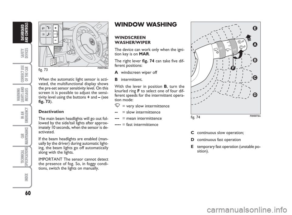
WINDOW WASHING
WINDSCREEN
WASHER/WIPER
The device can work only when the igni-
tion key is on MAR.
The right lever fig. 74can take five dif-
ferent positions:
Awindscreen wiper off
Bintermittent.
With the lever in position B, turn the
knurled ring Fto select one of four dif-
ferent speeds for the intermittent opera-
tion mode:
,= very slow intermittence
--= slow intermittence
---= mean intermittence
----= fast intermittence
When the automatic light sensor is acti-
vated, the multifunctional display shows
the pre-set sensor sensitivity level. On this
screen it is possible to adjust the sensi-
tivity level using the buttons +and –(see
fig. 73).
Deactivation
The main beam headlights will go out fol-
lowed by the side/tail lights after approx-
imately 10 seconds, when the sensor is de-
activated.
If the beam headlights are enabled (man-
ually by the driver) during automatic light-
ing, the beam lights go off automatically
along with the lights.
IMPORTANT The sensor cannot detect
the presence of fog. So, in foggy condi-
tions, switch the lights on manually.
fig. 73F0H0736m
fig. 74F0H0073m
Ccontinuous slow operation;
Dcontinuous fast operation
Etemporary fast operation (unstable po-
sition).
036-092 idea GB 1 ed 10-07-2008 16:12 Pagina 60
Page 62 of 210
61
SAFETY
DEVICES
CORRECT USE
OF THE CAR
WARNING
LIGHTS AND
MESSAGES
IN AN
EMERGENCY
CAR
MAINTENANCE
TECHNICAL
SPECIFICATIONS
INDEX
DASHBOARD
AND CONTROLS
Operation in position Eis limited to the
time during which the lever is kept in that
position manually. When released, the
stalk will return to position Aand the
wiper will be automatically stopped.
IMPORTANT Replace wiper blades as
specified in section “Car maintenance”.RAIN SENSOR
(where provided)
The rain sensor is located behind the dri-
ving mirror in contact with the windscreen
and has the purpose of automatically ad-
just the frequency of the windscreen
wiper strokes as to the rain intensity.
IMPORTANT Keep the window clean in
the sensor area.
Activation
Move the right lever down by one click.
The activation of the rain sensor is sig-
nalled by a control acquisition “stroke”.
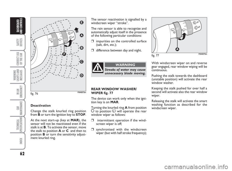
Turn the knurled ring F-fig. 76to increase
the rain sensor sensitivity.
The increase of the sensitivity of the rain
sensor is signalled by a control and acqui-
sition “stroke”.
By operating the windscreen washer with
the rain sensor enabled, a smart washing
cycle is carried out, without the addition-
al stroke after 5 seconds; once complet-
ed, the sensor resumes its regular auto-
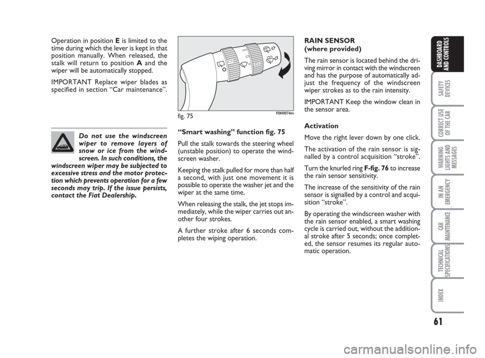
matic operation. “Smart washing” function fig. 75
Pull the stalk towards the steering wheel
(unstable position) to operate the wind-
screen washer.
Keeping the stalk pulled for more than half
a second, with just one movement it is
possible to operate the washer jet and the
wiper at the same time.
When releasing the stalk, the jet stops im-
mediately, while the wiper carries out an-
other four strokes.
A further stroke after 6 seconds com-
pletes the wiping operation. Do not use the windscreen
wiper to remove layers of
snow or ice from the wind-
screen. In such conditions, the
windscreen wiper may be subjected to
excessive stress and the motor protec-
tion which prevents operation for a few
seconds may trip. If the issue persists,
contact the Fiat Dealership.
fig. 75F0H0074m
036-092 idea GB 1 ed 10-07-2008 16:12 Pagina 61
Page 63 of 210
62
SAFETY
DEVICES
CORRECT USE
OF THE CAR
WARNING
LIGHTS AND
MESSAGES
IN AN
EMERGENCY
CAR
MAINTENANCE
TECHNICAL
SPECIFICATIONS
INDEX
DASHBOARD
AND CONTROLS
The sensor reactivation is signalled by a
windscreen wiper “stroke”.
The rain sensor is able to recognize and
automatically adjust itself in the presence
of the following particular conditions:
❒impurities on the controlled surface
(salt, dirt, etc.);
❒difference between day and night.
Deactivation
Change the stalk knurled ring position
from Bor turn the ignition key to STOP.
At the next start-up (key at MAR), the
sensor will not be reactivated even if the
stalk is at B. To activate the sensor, move
the stalk to position Aor Cand then to
position Bor turn the sensitivity adjust-
ment knurled ring.
fig. 76F0H0073m
Streaks of water may cause
unnecessary blade moving.
WARNINGWith windscreen wiper on and reverse
gear engaged, rear window wiping will be
continuous.
Pushing the stalk towards the dashboard
(unstable position) will activate the rear
window washer.
Keeping the stalk pushed for over half a
second will activate also the rear window
wiper.
Releasing the stalk will activate the smart
washing function as described for the
windscreen wiper.
fig. 77F0H0075m
REAR WINDOW WASHER/
WIPER fig. 77
The device can work only when the igni-
tion key is on MAR.
Turning the knurled ring Afrom position
åto position 'will operate the rear
window wiper as follows:
❒intermittent operation if the wind-
screen wiper is off;
❒synchronised with the windscreen
wiper (but with half stroke frequency);
036-092 idea GB 1 ed 10-07-2008 16:12 Pagina 62
Page 64 of 210
63
SAFETY
DEVICES
CORRECT USE
OF THE CAR
WARNING
LIGHTS AND
MESSAGES
IN AN
EMERGENCY
CAR
MAINTENANCE
TECHNICAL
SPECIFICATIONS
INDEX
DASHBOARD
AND CONTROLS
CRUISE CONTROL
(where provided)
It is a device able to support the driver,
with electronic control, which allows dri-
ving at speed over 30 km/h on long and
straight dry roads (e.g.: motorways), at a
desired speed, without pressing the ac-
celerator pedal. Therefore it is not sug-
gested to use this device on extra-urban
roads with traffic. Do not use it in town.
DEVICE ENGAGEMENT
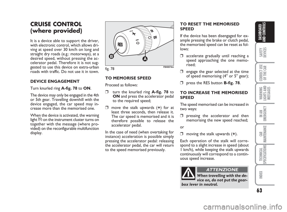
Turn knurled ring A-fig. 78to ON.
The device may only be engaged in the 4th
or 5th gear. Travelling downhill with the
device engaged, the car speed may in-
crease more than the memorised one.
When the device is activated, the warning
light
Üon the instrument cluster turns on
together with the message (where pro-
vided) on the reconfigurable multifunction
display.
fig. 78F0H0074m
TO MEMORISE SPEED
Proceed as follows:
❒turn the knurled ring A-fig. 78to
ONand press the accelerator pedal
to the required speed;
❒move the stalk upwards (+) for at
least three seconds, then release it.
The car speed is memorised and it is
therefore possible to release the
accelerator pedal.
In the case of need (when overtaking for
instance) acceleration is possible simply
pressing the accelerator pedal: releasing
the accelerator pedal, the car will return
to the speed memorised previously.TO RESET THE MEMORISED
SPEED
If the device has been disengaged for ex-
ample pressing the brake or clutch pedal,
the memorised speed can be reset as fol-
lows:
❒accelerate gradually until reaching a
speed approaching the one memo-
rised;
❒engage the gear selected at the time
of speed memorising (4thor 5thgear);
❒press the RES button B-fig. 78.
TO INCREASE THE MEMORISED
SPEED
The speed memorised can be increased in
two ways:
❒pressing the accelerator and then
memorising the new speed reached;
or
❒moving the stalk upwards (+).
Each operation of the stalk will corre-
spond to a slight increase in speed (about
1 km/h), while keeping the stalk upwards
continuously will correspond to a contin-
uous speed increase.
When travelling with the de-
vice on, do not put the gear-
box lever in neutral.
ATTENZIONE
036-092 idea GB 1 ed 10-07-2008 16:12 Pagina 63