technical specifications FIAT IDEA 2012 1.G Repair Manual
[x] Cancel search | Manufacturer: FIAT, Model Year: 2012, Model line: IDEA, Model: FIAT IDEA 2012 1.GPages: 210, PDF Size: 3.65 MB
Page 65 of 210
64
SAFETY
DEVICES
CORRECT USE
OF THE CAR
WARNING
LIGHTS AND
MESSAGES
IN AN
EMERGENCY
CAR
MAINTENANCE
TECHNICAL
SPECIFICATIONS
INDEX
DASHBOARD
AND CONTROLS
TO REDUCE MEMORISED
SPEED
The speed memorised can be increased in
two ways:
❒disengaging the device and then
memorising the new speed;
or
❒moving the stalk downwards (–) until
reaching the new speed which will be
memorised automatically.
Each operation of the stalk will corre-
spond to a slight reduction in speed (about
1 km/h), while keeping the stalk down-
wards continuously will correspond to a
continuous speed reduction.
DEVICE DISENGAGEMENT
Turn the ring A-fig. 78to OFFor the ig-
nition key to STOP. The device is auto-
matically deactivated also in one of the fol-
lowing cases:
❒pressing the brake or clutch pedal.
In the event of device mal-
function or failure, turn the
knurled ring A to OFF and contact a
Fiat Dealership after checking the
protective fuse integrity.
WARNING
CEILING LIGHTS
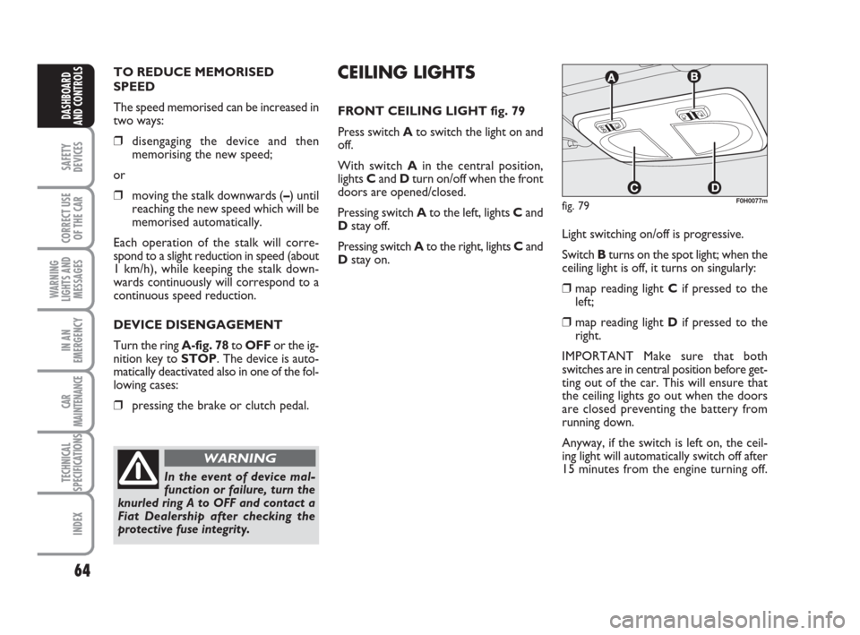
FRONT CEILING LIGHT fig. 79
Press switch Ato switch the light on and
off.
With switch Ain the central position,
lights Cand Dturn on/off when the front
doors are opened/closed.
Pressing switch Ato the left, lights Cand
Dstay off.
Pressing switch Ato the right, lights Cand
Dstay on.
fig. 79F0H0077m
Light switching on/off is progressive.
Switch Bturns on the spot light; when the
ceiling light is off, it turns on singularly:
❒map reading light Cif pressed to the
left;
❒map reading light Dif pressed to the
right.
IMPORTANT Make sure that both
switches are in central position before get-
ting out of the car. This will ensure that
the ceiling lights go out when the doors
are closed preventing the battery from
running down.
Anyway, if the switch is left on, the ceil-
ing light will automatically switch off after
15 minutes from the engine turning off.
036-092 idea GB 1 ed 10-07-2008 16:12 Pagina 64
Page 66 of 210
65
SAFETY
DEVICES
CORRECT USE
OF THE CAR
WARNING
LIGHTS AND
MESSAGES
IN AN
EMERGENCY
CAR
MAINTENANCE
TECHNICAL
SPECIFICATIONS
INDEX
DASHBOARD
AND CONTROLS
Ceiling light timing
Two timing strategies are available in or-
der to facilitate getting in and out of the
car, especially at night in dark areas:
T
IMING FOR GETTING INTO THE CAR
The ceiling lights will come on as follows:
❒for about 10 seconds when a door is
unlocked;
❒for about 3 minutes when a door is
opened;
❒for about 10 seconds when a door is
closed (within the 3 minutes).
Timing will be stopped when the ignition
key is turned to MAR.
T
IMING FOR GETTING OUT OF THE CAR
The ceiling lights will come on as follows
when the key is removed from the igni-
tion switch:
❒for about 10 seconds within 2 min-
utes after stopping the engine;
❒for about 3 minutes when a door is
opened;
❒for about 10 seconds when a door is
closed (within the three minutes).
The timeout will automatically end when
the doors are locked.
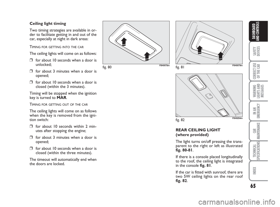
fig. 80F0H0078mfig. 81F0H0079m
fig. 82F0H0254m
REAR CEILING LIGHT
(where provided)
The light turns on/off pressing the trans-
parent to the right or left as illustrated
fig. 80-81.
If there is a console placed longitudinally
to the roof, the ceiling light is integrated
in the console fig. 81.
If the car is fitted with sunroof, there are
two 5W ceiling lights on the rear roof
fig. 82.
036-092 idea GB 1 ed 10-07-2008 16:12 Pagina 65
Page 67 of 210
66
SAFETY
DEVICES
CORRECT USE
OF THE CAR
WARNING
LIGHTS AND
MESSAGES
IN AN
EMERGENCY
CAR
MAINTENANCE
TECHNICAL
SPECIFICATIONS
INDEX
DASHBOARD
AND CONTROLS
CONTROLS
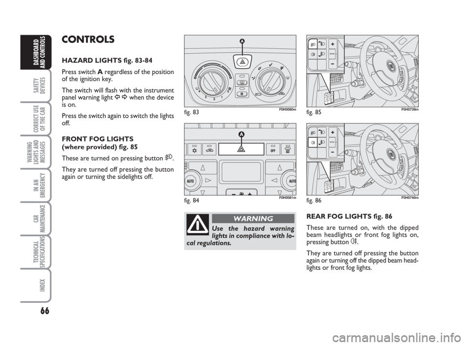
HAZARD LIGHTS fig. 83-84
Press switch Aregardless of the position
of the ignition key.
The switch will flash with the instrument
panel warning light
Î¥when the device
is on.
Press the switch again to switch the lights
off.
FRONT FOG LIGHTS
(where provided) fig. 85
These are turned on pressing button
5.
They are turned off pressing the button
again or turning the sidelights off.
REAR FOG LIGHTS fig. 86
These are turned on, with the dipped
beam headlights or front fog lights on,
pressing button
4.
They are turned off pressing the button
again or turning off the dipped beam head-
lights or front fog lights.
fig. 83F0H0080m
fig. 84F0H0081m
fig. 85F0H0739m
Use the hazard warning
lights in compliance with lo-
cal regulations.
WARNING
fig. 86F0H0740m
036-092 idea GB 1 ed 10-07-2008 16:12 Pagina 66
Page 68 of 210
67
SAFETY
DEVICES
CORRECT USE
OF THE CAR
WARNING
LIGHTS AND
MESSAGES
IN AN
EMERGENCY
CAR
MAINTENANCE
TECHNICAL
SPECIFICATIONS
INDEX
DASHBOARD
AND CONTROLS
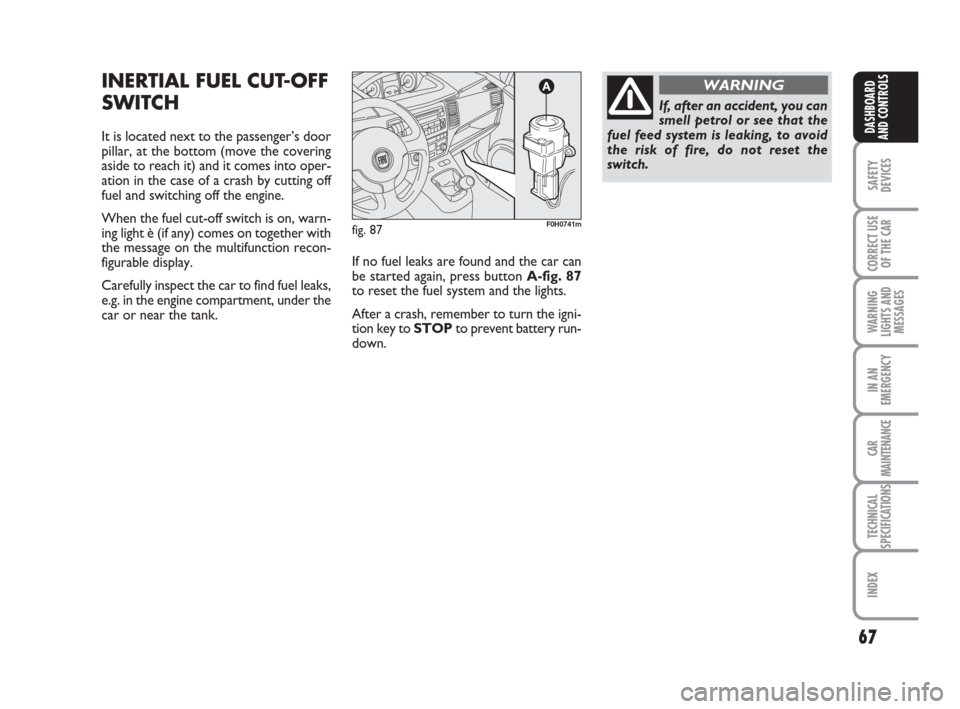
INERTIAL FUEL CUT-OFF
SWITCH
It is located next to the passenger’s door
pillar, at the bottom (move the covering
aside to reach it) and it comes into oper-
ation in the case of a crash by cutting off
fuel and switching off the engine.
When the fuel cut-off switch is on, warn-
ing light è (if any) comes on together with
the message on the multifunction recon-
figurable display.
Carefully inspect the car to find fuel leaks,
e.g. in the engine compartment, under the
car or near the tank.If no fuel leaks are found and the car can
be started again, press button A-fig. 87
to reset the fuel system and the lights.
After a crash, remember to turn the igni-
tion key to STOPto prevent battery run-
down.
fig. 87F0H0741m
If, after an accident, you can
smell petrol or see that the
fuel feed system is leaking, to avoid
the risk of fire, do not reset the
switch.
WARNING
036-092 idea GB 1 ed 10-07-2008 16:12 Pagina 67
Page 69 of 210
68
SAFETY
DEVICES
CORRECT USE
OF THE CAR
WARNING
LIGHTS AND
MESSAGES
IN AN
EMERGENCY
CAR
MAINTENANCE
TECHNICAL
SPECIFICATIONS
INDEX
DASHBOARD
AND CONTROLS
INTERIOR EQUIPMENT
UPPER GLOVEBOX
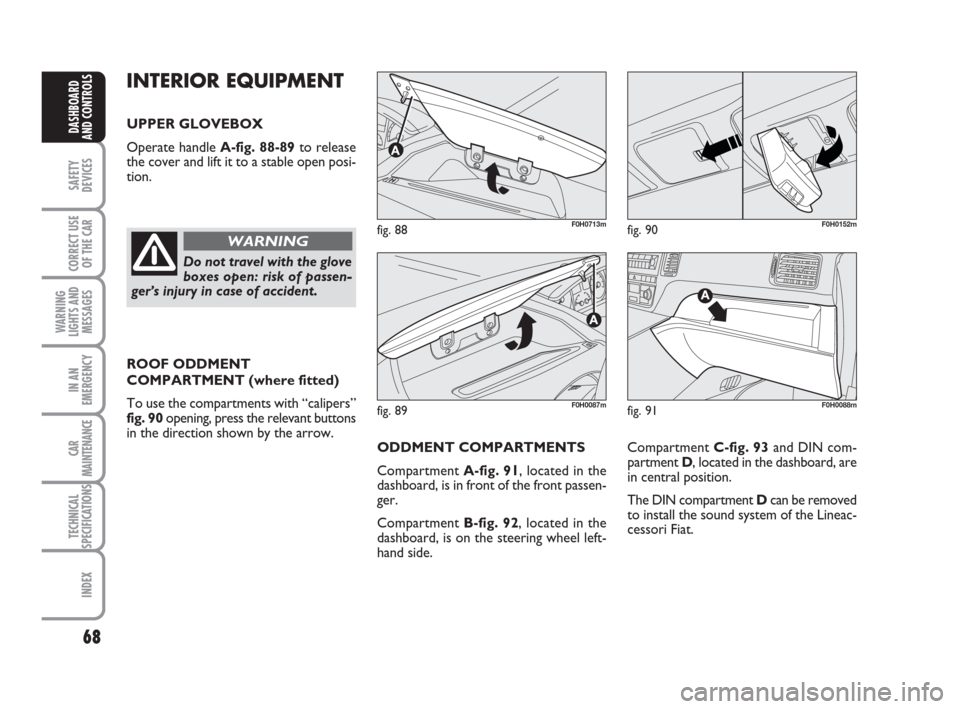
Operate handle A-fig. 88-89to release
the cover and lift it to a stable open posi-
tion.
ROOF ODDMENT
COMPARTMENT (where fitted)
To use the compartments with “calipers”
fig. 90 opening, press the relevant buttons
in the direction shown by the arrow.
fig. 88F0H0713m
fig. 89F0H0087m
fig. 90F0H0152m
Do not travel with the glove
boxes open: risk of passen-
ger’s injury in case of accident.
WARNING
Compartment C-fig. 93and DIN com-
partment D, located in the dashboard, are
in central position.
The DIN compartment Dcan be removed
to install the sound system of the Lineac-
cessori Fiat.
fig. 91F0H0088m
ODDMENT COMPARTMENTS
Compartment A-fig. 91, located in the
dashboard, is in front of the front passen-
ger.
Compartment B-fig. 92, located in the
dashboard, is on the steering wheel left-
hand side.
036-092 idea GB 1 ed 10-07-2008 16:12 Pagina 68
Page 70 of 210

69
SAFETY
DEVICES
CORRECT USE
OF THE CAR
WARNING
LIGHTS AND
MESSAGES
IN AN
EMERGENCY
CAR
MAINTENANCE
TECHNICAL
SPECIFICATIONS
INDEX
DASHBOARD
AND CONTROLS
fig. 93F0H0090m
fig. 92F0H0714m
DOOR POCKETS fig. 94
Each door has a pocket/oddment com-
partment.GLASS/CAN HOLDER fig. 95
The central console houses the glass/can
holders in front of the handbrake.
Cargo box (where provided) fig. 96
It is made up of a special preformed ele-
ment, which is placed in the boot for cars
with non sliding rear seat and can be used
to house objects; this element provides
load plane uniform level with depressed
seat back.
MAGNETIC CARD/TICKET
SLOTS fig. 97
The slots for holding magnetic cards and
tickets (phone card, toll slips, etc.) can be
found on the central tunnel unit.
fig. 94F0H0153mfig. 95F0H0091m
fig. 96F0H0349m
fig. 97F0H0092m
036-092 idea GB 1 ed 10-07-2008 16:12 Pagina 69
Page 71 of 210
70
SAFETY
DEVICES
CORRECT USE
OF THE CAR
WARNING
LIGHTS AND
MESSAGES
IN AN
EMERGENCY
CAR
MAINTENANCE
TECHNICAL
SPECIFICATIONS
INDEX
DASHBOARD
AND CONTROLS
fig. 98F0H0093m
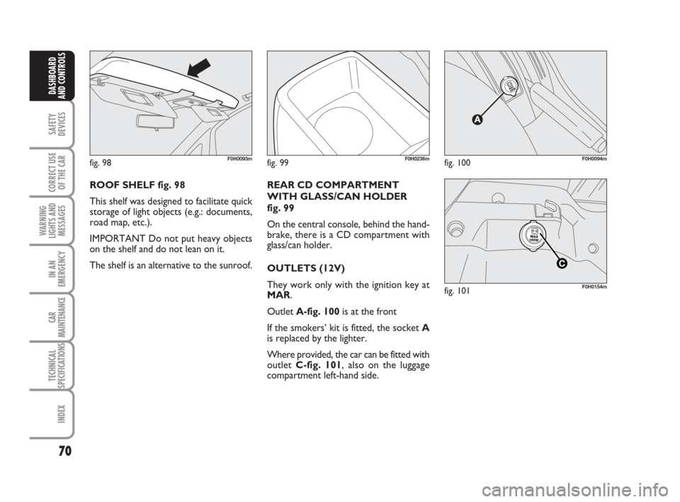
ROOF SHELF fig. 98
This shelf was designed to facilitate quick
storage of light objects (e.g.: documents,
road map, etc.).
IMPORTANT Do not put heavy objects
on the shelf and do not lean on it.
The shelf is an alternative to the sunroof.
fig. 99F0H0236mfig. 100F0H0094m
REAR CD COMPARTMENT
WITH GLASS/CAN HOLDER
fig. 99
On the central console, behind the hand-
brake, there is a CD compartment with
glass/can holder.
OUTLETS (12V)
They work only with the ignition key at
MAR.
Outlet A-fig. 100is at the front
If the smokers’ kit is fitted, the socket A
is replaced by the lighter.
Where provided, the car can be fitted with
outlet C-fig. 101, also on the luggage
compartment left-hand side.
fig. 101F0H0154m
036-092 idea GB 1 ed 10-07-2008 16:12 Pagina 70
Page 72 of 210
71
SAFETY
DEVICES
CORRECT USE
OF THE CAR
WARNING
LIGHTS AND
MESSAGES
IN AN
EMERGENCY
CAR
MAINTENANCE
TECHNICAL
SPECIFICATIONS
INDEX
DASHBOARD
AND CONTROLS
SMOKER’S KIT
(where provided)
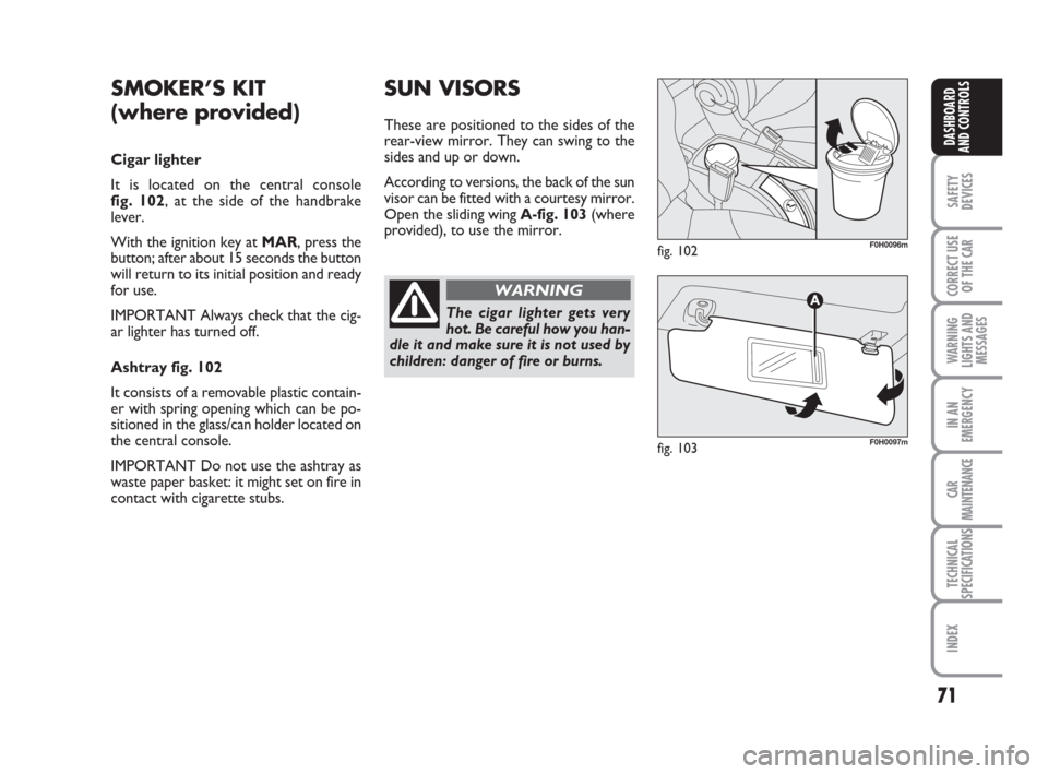
Cigar lighter
It is located on the central console
fig. 102, at the side of the handbrake
lever.
With the ignition key at MAR, press the
button; after about 15 seconds the button
will return to its initial position and ready
for use.
IMPORTANT Always check that the cig-
ar lighter has turned off.
Ashtray fig. 102
It consists of a removable plastic contain-
er with spring opening which can be po-
sitioned in the glass/can holder located on
the central console.
IMPORTANT Do not use the ashtray as
waste paper basket: it might set on fire in
contact with cigarette stubs.
SUN VISORS
These are positioned to the sides of the
rear-view mirror. They can swing to the
sides and up or down.
According to versions, the back of the sun
visor can be fitted with a courtesy mirror.
Open the sliding wing A-fig. 103(where
provided), to use the mirror.
fig. 102F0H0096m
fig. 103F0H0097m
The cigar lighter gets very
hot. Be careful how you han-
dle it and make sure it is not used by
children: danger of fire or burns.
WARNING
036-092 idea GB 1 ed 10-07-2008 16:12 Pagina 71
Page 73 of 210
72
SAFETY
DEVICES
CORRECT USE
OF THE CAR
WARNING
LIGHTS AND
MESSAGES
IN AN
EMERGENCY
CAR
MAINTENANCE
TECHNICAL
SPECIFICATIONS
INDEX
DASHBOARD
AND CONTROLS
SUNROOF
(where provided)
The sunroof is fitted with a safety anti-
crushing system able to detect the pres-
ence of an obstacle during the window
winding up; should it happen, the system
stops and lowers the window.
The sunroof is fitted with a “skydome”
consisting of two glass panels - one fixed
and one moving - with sun visors operat-
ed manually in two positions (open/
closed). The sunroof will only work when
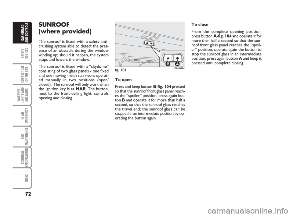
the ignition key is at MAR. The button,
next to the front ceiling light, controls
opening and closing. To close
From the complete opening position,
press button A-fig. 104and operate it for
more than half a second so that the sun-
roof front glass panel reaches the “spoil-
er” position; operate again the button to
stop the sunroof glass in an intermediate
position; press again button Aand keep it
pressed until complete closing.
fig. 104F0H0098m
To open
Press and keep button B-fig. 104pressed
so that the sunroof front glass panel reach-
es the “spoiler” position; press again but-
ton Band operate it for more than half a
second, so that the sunroof glass reaches
the travel end; the sunroof glass can be
stopped in an intermediate position by op-
erating the button again.
036-092 idea GB 1 ed 10-07-2008 16:12 Pagina 72
Page 74 of 210
73
SAFETY
DEVICES
CORRECT USE
OF THE CAR
WARNING
LIGHTS AND
MESSAGES
IN AN
EMERGENCY
CAR
MAINTENANCE
TECHNICAL
SPECIFICATIONS
INDEX
DASHBOARD
AND CONTROLS
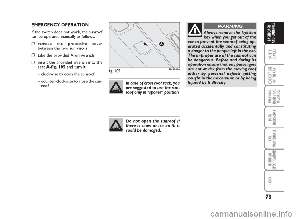
fig. 105F0H0099m
EMERGENCY OPERATION
If the switch does not work, the sunroof
can be operated manually as follows:
❒remove the protective cover
between the two sun visors
❒take the provided Allen wrench
❒insert the provided wrench into the
seat A-fig. 105and turn it:
– clockwise to open the sunroof
– counter-clockwise to close the sun-
roof.In case of cross roof rack, you
are suggested to use the sun-
roof only in “spoiler” position.
Do not open the sunroof if
there is snow or ice on it: it
could be damaged.
Always remove the ignition
key when you get out of the
car to prevent the sunroof being op-
erated accidentally and constituting
a danger to the people left in the car.
The improper use of the sunroof can
be dangerous. Before and during its
operation ensure that any passengers
are not at risk from the moving roof
either by personal objects getting
caught in the mechanism or by being
injured by it directly.
WARNING
036-092 idea GB 1 ed 10-07-2008 16:12 Pagina 73