FIAT LINEA 2007 1.G Owners Manual
Manufacturer: FIAT, Model Year: 2007, Model line: LINEA, Model: FIAT LINEA 2007 1.GPages: 230, PDF Size: 3.31 MB
Page 161 of 230
160
WARNING
LIGHTS AND
MESSAGES
CAR
MAINTENANCE
TECHNICAL
SPECIFICATIONS
IINDEX
DASHBOARD
AND CONTROLS
SAFETY
DEVICES
CORRECT USE
OF THE
CAR
IN AN
EMERGENCY
IF AN EXTERIOR LIGHT
BURNS OUT
For the type of bulb and power rating, see
“When needing to change a bulb”.
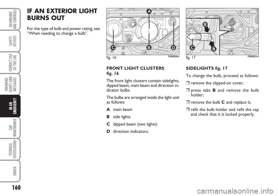
FRONT LIGHT CLUSTERS
fig. 16
The front light clusters contain sidelights,
dipped beam, main beam and direction in-
dicator bulbs.
The bulbs are arranged inside the light unit
as follows:
Amain beam
Bside lights
Cdipped beam (two lights)
Ddirection indicators. SIDELIGHTS fig. 17
To change the bulb, proceed as follows:
❒remove the clipped-on cover;
❒press tabs Band remove the bulb
holder;
❒remove the bulb Cand replace it;
❒refit the bulb holder and refit the cap
and check that it is locked properly.
fig. 16
CBD
A
F0R0220mfig. 17F0R0221m
Page 162 of 230
161
WARNING
LIGHTS AND
MESSAGES
CAR
MAINTENANCE
TECHNICAL
SPECIFICATIONS
INDEX
DASHBOARD
AND CONTROLS
SAFETY
DEVICES
CORRECT USE
OF THE
CAR
IN AN
EMERGENCY
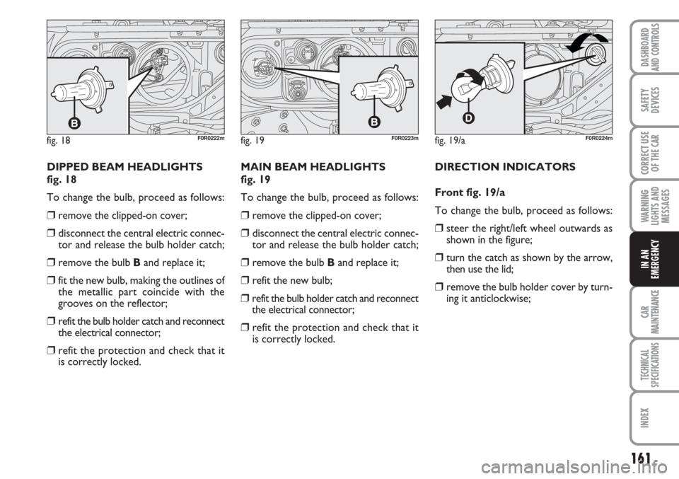
DIPPED BEAM HEADLIGHTS
fig. 18
To change the bulb, proceed as follows:
❒remove the clipped-on cover;
❒disconnect the central electric connec-
tor and release the bulb holder catch;
❒remove the bulb Band replace it;
❒fit the new bulb, making the outlines of
the metallic part coincide with the
grooves on the reflector;
❒refit the bulb holder catch and reconnect
the electrical connector;
❒refit the protection and check that it
is correctly locked.MAIN BEAM HEADLIGHTS
fig. 19
To change the bulb, proceed as follows:
❒remove the clipped-on cover;
❒disconnect the central electric connec-
tor and release the bulb holder catch;
❒remove the bulb Band replace it;
❒refit the new bulb;
❒refit the bulb holder catch and reconnect
the electrical connector;
❒refit the protection and check that it
is correctly locked.DIRECTION INDICATORS
Front fig. 19/a
To change the bulb, proceed as follows:
❒steer the right/left wheel outwards as
shown in the figure;
❒turn the catch as shown by the arrow,
then use the lid;
❒remove the bulb holder cover by turn-
ing it anticlockwise;
fig. 18F0R0222mfig. 19/aF0R0224mfig. 19F0R0223m
Page 163 of 230
162
WARNING
LIGHTS AND
MESSAGES
CAR
MAINTENANCE
TECHNICAL
SPECIFICATIONS
IINDEX
DASHBOARD
AND CONTROLS
SAFETY
DEVICES
CORRECT USE
OF THE
CAR
IN AN
EMERGENCY
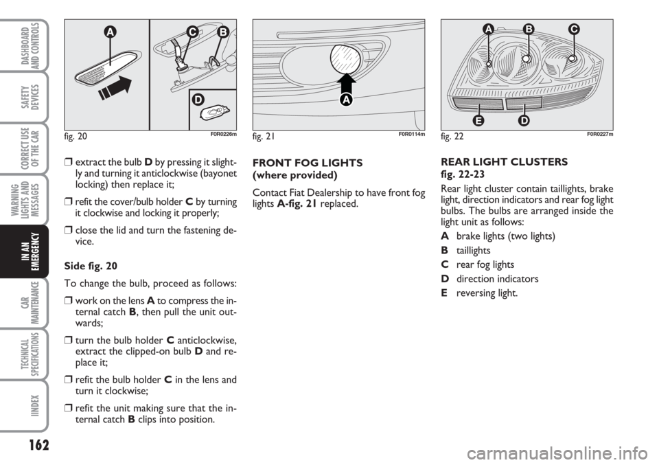
❒extract the bulb Dby pressing it slight-
ly and turning it anticlockwise (bayonet
locking) then replace it;
❒refit the cover/bulb holder Cby turning
it clockwise and locking it properly;
❒close the lid and turn the fastening de-
vice.
Side fig. 20
To change the bulb, proceed as follows:
❒work on the lens Ato compress the in-
ternal catch B, then pull the unit out-
wards;
❒turn the bulb holder Canticlockwise,
extract the clipped-on bulb Dand re-
place it;
❒refit the bulb holder Cin the lens and
turn it clockwise;
❒refit the unit making sure that the in-
ternal catch Bclips into position.FRONT FOG LIGHTS
(where provided)
Contact Fiat Dealership to have front fog
lights A-fig. 21replaced.REAR LIGHT CLUSTERS
fig. 22-23
Rear light cluster contain taillights, brake
light, direction indicators and rear fog light
bulbs. The bulbs are arranged inside the
light unit as follows:
Abrake lights (two lights)
Btaillights
Crear fog lights
Ddirection indicators
Ereversing light.
fig. 20F0R0226mfig. 22
D
ABC
E
F0R0227mfig. 21F0R0114m
Page 164 of 230
163
WARNING
LIGHTS AND
MESSAGES
CAR
MAINTENANCE
TECHNICAL
SPECIFICATIONS
INDEX
DASHBOARD
AND CONTROLS
SAFETY
DEVICES
CORRECT USE
OF THE
CAR
IN AN
EMERGENCY
fig. 23/aF0R0228m
fig. 24F0R0230m
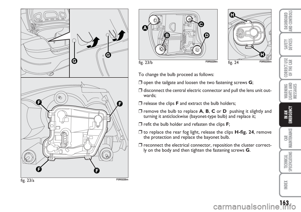
To change the bulb proceed as follows:
❒open the tailgate and loosen the two fastening screws G;
❒disconnect the central electric connector and pull the lens unit out-
wards;
❒release the clips Fand extract the bulb holders;
❒remove the bulb to replace A, B, Cor D pushing it slightly and
turning it anticlockwise (bayonet-type bulb) and replace it;
❒refit the bulb holder and refasten the clips F;
❒to replace the rear fog light, release the clips H-fig. 24, remove
the protection and replace the bayonet bulb.
❒reconnect the electrical connector, reposition the cluster correct-
ly on the body and then tighten the fastening screws G.
fig. 23/bF0R0229m
Page 165 of 230
164
WARNING
LIGHTS AND
MESSAGES
CAR
MAINTENANCE
TECHNICAL
SPECIFICATIONS
IINDEX
DASHBOARD
AND CONTROLS
SAFETY
DEVICES
CORRECT USE
OF THE
CAR
IN AN
EMERGENCY
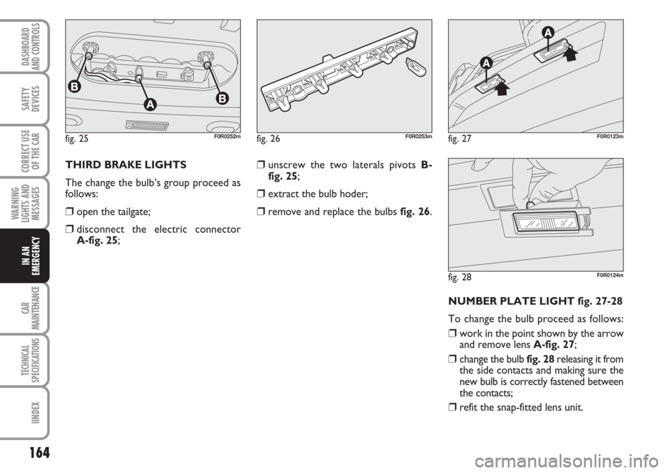
THIRD BRAKE LIGHTS
The change the bulb’s group proceed as
follows:
❒open the tailgate;
❒disconnect the electric connector
A-fig. 25;
❒unscrew the two laterals pivots B-
fig. 25;
❒extract the bulb hoder;
❒remove and replace the bulbs fig. 26.
NUMBER PLATE LIGHT fig. 27-28
To change the bulb proceed as follows:
❒work in the point shown by the arrow
and remove lens A-fig. 27;
❒change the bulb fig. 28releasing it from
the side contacts and making sure the
new bulb is correctly fastened between
the contacts;
❒refit the snap-fitted lens unit.
fig. 25F0R0252mfig. 26F0R0253mfig. 27F0R0123m
fig. 28F0R0124m
Page 166 of 230
165
WARNING
LIGHTS AND
MESSAGES
CAR
MAINTENANCE
TECHNICAL
SPECIFICATIONS
INDEX
DASHBOARD
AND CONTROLS
SAFETY
DEVICES
CORRECT USE
OF THE
CAR
IN AN
EMERGENCY
IF AN INTERIOR LIGHT
BURNS OUT
For the type of bulb and power rating, see
“When needing to change a bulb”.
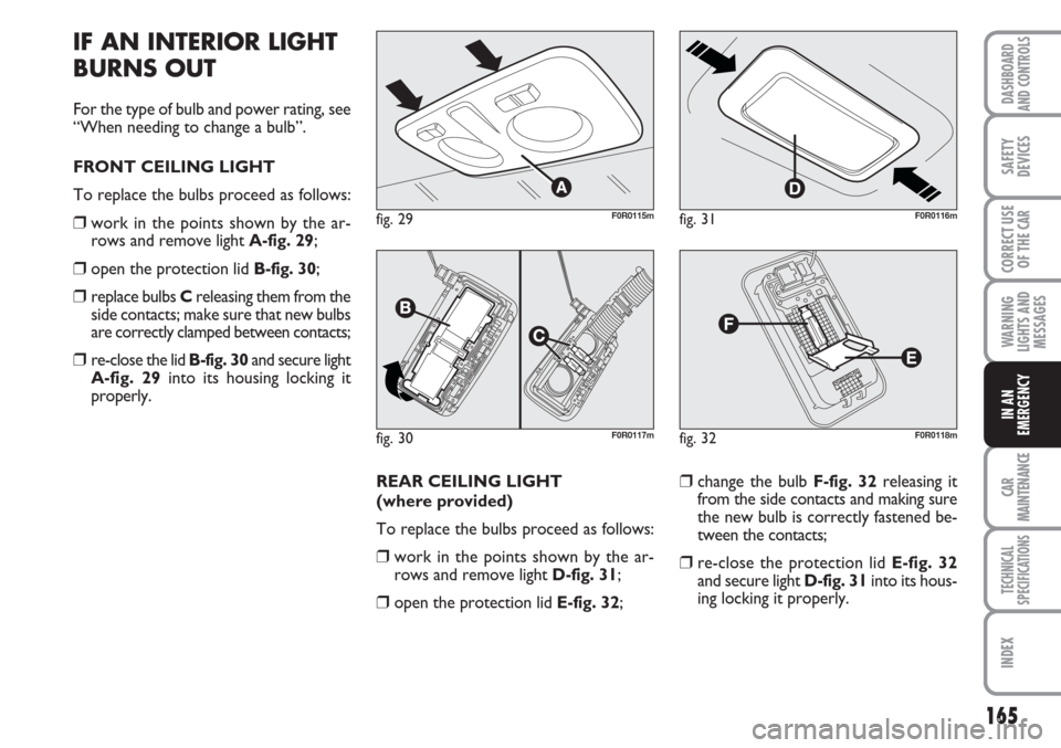
FRONT CEILING LIGHT
To replace the bulbs proceed as follows:
❒work in the points shown by the ar-
rows and remove light A-fig. 29;
❒open the protection lid B-fig. 30;
❒replace bulbs Creleasing them from the
side contacts; make sure that new bulbs
are correctly clamped between contacts;
❒re-close the lid B-fig. 30and secure light
A-fig. 29into its housing locking it
properly.
REAR CEILING LIGHT
(where provided)
To replace the bulbs proceed as follows:
❒work in the points shown by the ar-
rows and remove light D-fig. 31;
❒open the protection lid E-fig. 32;
❒change the bulb F-fig. 32releasing it
from the side contacts and making sure
the new bulb is correctly fastened be-
tween the contacts;
❒re-close the protection lid E-fig. 32
and secure light D-fig. 31into its hous-
ing locking it properly.
fig. 29F0R0115m
fig. 30F0R0117m
fig. 31F0R0116m
fig. 32F0R0118m
Page 167 of 230
166
WARNING
LIGHTS AND
MESSAGES
CAR
MAINTENANCE
TECHNICAL
SPECIFICATIONS
IINDEX
DASHBOARD
AND CONTROLS
SAFETY
DEVICES
CORRECT USE
OF THE
CAR
IN AN
EMERGENCY
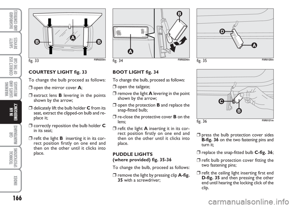
COURTESY LIGHT fig. 33
To change the bulb proceed as follows:
❒open the mirror cover A;
❒extract lens Blevering in the points
shown by the arrow;
❒delicately lift the bulb holder Cfrom its
seat, extract the clipped-on bulb and re-
place it;
❒correctly reposition the bulb holder C
in its seat;
❒refit the light Binserting it in its cor-
rect position firstly on one end and
then on the other until it clicks into
place.BOOT LIGHT fig. 34
To change the bulb, proceed as follows:
❒open the tailgate;
❒remove the light Alevering in the point
shown by the arrow;
❒open the protection Band replace the
snap-fitted bulb;
❒re-close the protective cover Bon the
lens;
❒refit the light Ainserting it in its cor-
rect position firstly on one end and
then on the other until it clicks into
place.
PUDDLE LIGHTS
(where provided) fig. 35-36
To change the bulb, proceed as follows:
❒remove the light by pressing clip A-fig.
35with a screwdriver;
❒press the bulb protection cover sides
B-fig. 36on the two fastening pins and
turn it;
❒replace the snap-fitted bulb C-fig. 36;
❒refit bulb protection cover fitting the
two fastening pins;
❒refit the ceiling light inserting first end
D-fig. 35and then pressing the other
end until hearing the locking click of the
clip.
fig. 33F0R0233mfig. 34F0R0234mfig. 35F0R0120m
fig. 36F0R0121m
Page 168 of 230
167
WARNING
LIGHTS AND
MESSAGES
CAR
MAINTENANCE
TECHNICAL
SPECIFICATIONS
INDEX
DASHBOARD
AND CONTROLS
SAFETY
DEVICES
CORRECT USE
OF THE
CAR
IN AN
EMERGENCY
IF A FUSE BLOWS
GENERAL
The fuse is a protective device for the
electric system: it comes into action (i.e.
it cuts off) mainly due to a fault or im-
proper action on the system.
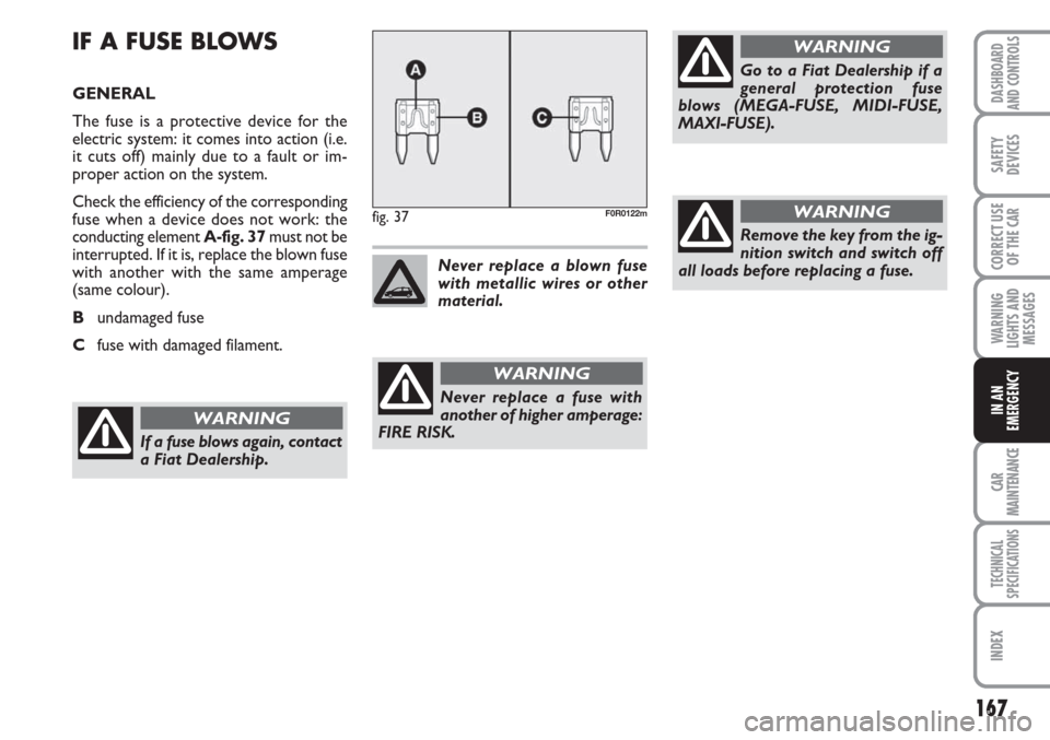
Check the efficiency of the corresponding
fuse when a device does not work: the
conducting element A-fig. 37must not be
interrupted. If it is, replace the blown fuse
with another with the same amperage
(same colour).
Bundamaged fuse
Cfuse with damaged filament.
fig. 37F0R0122m
Never replace a fuse with
another of higher amperage:
FIRE RISK.
WARNING
Never replace a blown fuse
with metallic wires or other
material.
Go to a Fiat Dealership if a
general protection fuse
blows (MEGA-FUSE, MIDI-FUSE,
MAXI-FUSE).
WARNING
If a fuse blows again, contact
a Fiat Dealership.
WARNING
Remove the key from the ig-
nition switch and switch off
all loads before replacing a fuse.
WARNING
Page 169 of 230
168
WARNING
LIGHTS AND
MESSAGES
CAR
MAINTENANCE
TECHNICAL
SPECIFICATIONS
IINDEX
DASHBOARD
AND CONTROLS
SAFETY
DEVICES
CORRECT USE
OF THE
CAR
IN AN
EMERGENCY
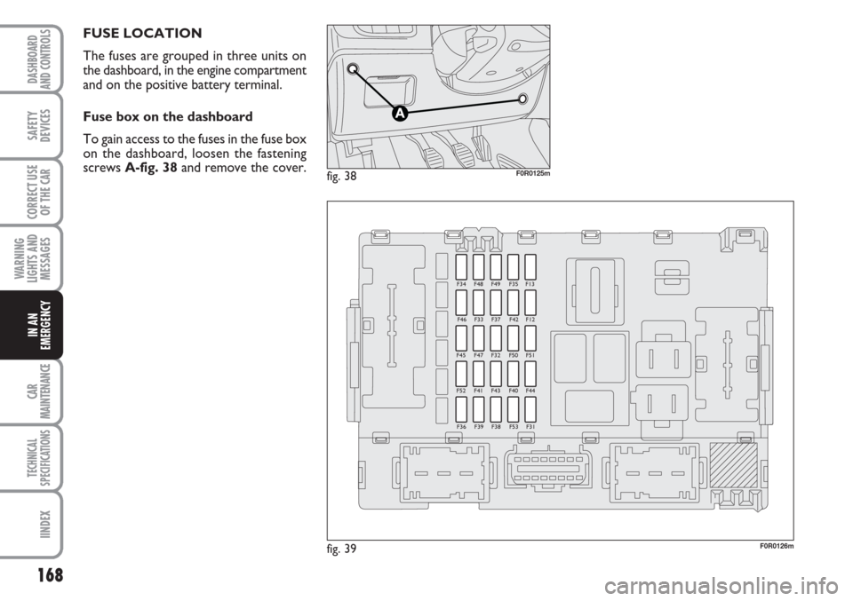
FUSE LOCATION
The fuses are grouped in three units on
the dashboard, in the engine compartment
and on the positive battery terminal.
Fuse box on the dashboard
To gain access to the fuses in the fuse box
on the dashboard, loosen the fastening
screws A-fig. 38and remove the cover.
fig. 39F0R0126m
F34 F48 F49 F35 F13
F46 F33 F37 F42 F12
F45 F47 F32 F50 F51
F52 F41 F43 F40 F44
F36 F39 F38 F53 F31
fig. 38F0R0125m
Page 170 of 230
169
WARNING
LIGHTS AND
MESSAGES
CAR
MAINTENANCE
TECHNICAL
SPECIFICATIONS
INDEX
DASHBOARD
AND CONTROLS
SAFETY
DEVICES
CORRECT USE
OF THE
CAR
IN AN
EMERGENCY
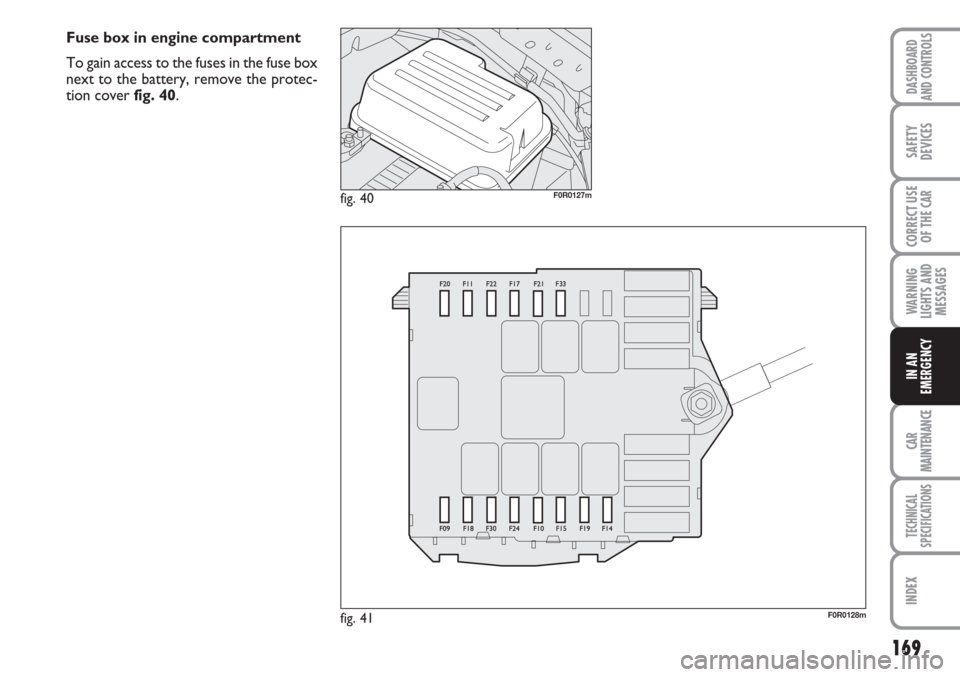
Fuse box in engine compartment
To gain access to the fuses in the fuse box
next to the battery, remove the protec-
tion cover fig. 40.
fig. 40F0R0127m
fig. 41F0R0128m