technical specifications FIAT LINEA 2007 1.G Service Manual
[x] Cancel search | Manufacturer: FIAT, Model Year: 2007, Model line: LINEA, Model: FIAT LINEA 2007 1.GPages: 230, PDF Size: 3.31 MB
Page 45 of 230
44
SAFETY
DEVICES
CORRECT USE
OF THE
CAR
WARNING
LIGHTS AND
MESSAGES
IN AN
EMERGENCY
CAR
MAINTENANCE
TECHNICAL
SPECIFICATIONS
INDEX
DASHBOARD
AND CONTROLS
The fabric upholstery of your
car is designed to withstand
the normal wear and tear of
your car for a long time. Some
precautions are however needed. Avoid
prolonged rubbing against clothing ac-
cessories, such as metal buckles, Velcro
strips and the like, which by applying a
high pressure on the fabric in a small
area could cause the breakage of some
threads and damage the upholstery.
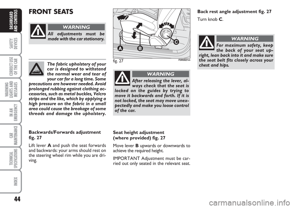
Seat height adjustment
(where provided) fig. 27
Move lever Bupwards or downwards to
achieve the required height.
IMPORTANT Adjustment must be car-
ried out only seated in the relevant seat.
FRONT SEATS
fig. 27F0R0021m
All adjustments must be
made with the car stationary.
WARNING
Backwards/Forwards adjustment
fig. 27
Lift lever Aand push the seat forwards
and backwards: your arms should rest on
the steering wheel rim while you are dri-
ving.
After releasing the lever, al-
ways check that the seat is
locked on the guides by trying to
move it backwards and forth. If it is
not locked, the seat may move unex-
pectedly and make you loose control
of the car.
WARNING
For maximum safety, keep
the back of your seat up-
right, lean back into it and make sure
the seat belt fits closely across your
chest and hips.
WARNING
Back rest angle adjustment fig. 27
Turn knob C.
Page 46 of 230
45
SAFETY
DEVICES
CORRECT USE
OF THE
CAR
WARNING
LIGHTS AND
MESSAGES
IN AN
EMERGENCY
CAR
MAINTENANCE
TECHNICAL
SPECIFICATIONS
INDEX
DASHBOARD
AND CONTROLS
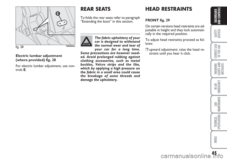
fig. 28F0R0022m
Electric lumbar adjustment
(where provided) fig. 28
For electric lumbar adjustment, use con-
trols E.The fabric upholstery of your
car is designed to withstand
the normal wear and tear of
your car for a long time.
Some precautions are however need-
ed. Avoid prolonged rubbing against
clothing accessories, such as metal
buckles, Velcro strips and the like,
which by applying a high pressure on
the fabric in a small area could cause
the breakage of some threads and
damage the upholstery.
HEAD RESTRAINTS
FRONT fig. 29
On certain versions head restraints are ad-
justable in height and they lock automati-
cally in the required position.
To adjust head restraints proceed as fol-
lows:
❒upward adjustment: raise the head re-
straint until you hear it click.
REAR SEATS
To folds the rear seats refer to paragraph
“Extending the boot” in this section.
Page 47 of 230
46
SAFETY
DEVICES
CORRECT USE
OF THE
CAR
WARNING
LIGHTS AND
MESSAGES
IN AN
EMERGENCY
CAR
MAINTENANCE
TECHNICAL
SPECIFICATIONS
INDEX
DASHBOARD
AND CONTROLS
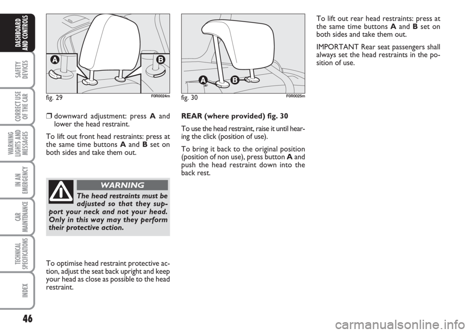
❒downward adjustment: press Aand
lower the head restraint.
To lift out front head restraints: press at
the same time buttons Aand Bset on
both sides and take them out.REAR (where provided) fig. 30
To use the head restraint, raise it until hear-
ing the click (position of use).
To bring it back to the original position
(position of non use), press button Aand
push the head restraint down into the
back rest.
fig. 29F0R0024mfig. 30F0R0025m
To optimise head restraint protective ac-
tion, adjust the seat back upright and keep
your head as close as possible to the head
restraint.
The head restraints must be
adjusted so that they sup-
port your neck and not your head.
Only in this way may they perform
their protective action.
WARNING
To lift out rear head restraints: press at
the same time buttons Aand Bset on
both sides and take them out.
IMPORTANT Rear seat passengers shall
always set the head restraints in the po-
sition of use.
Page 48 of 230
47
SAFETY
DEVICES
CORRECT USE
OF THE
CAR
WARNING
LIGHTS AND
MESSAGES
IN AN
EMERGENCY
CAR
MAINTENANCE
TECHNICAL
SPECIFICATIONS
INDEX
DASHBOARD
AND CONTROLS
REARVIEW MIRRORS
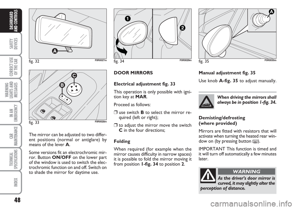
DRIVING MIRROR fig. 32
The mirror is fitted with a safety device
that causes it to be released in the event
of a violent crash.
STEERING WHEEL
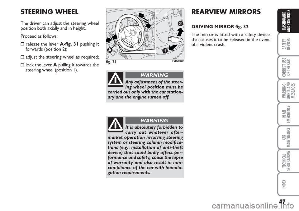
The driver can adjust the steering wheel
position both axially and in height.
Proceed as follows:
❒release the lever A-fig. 31pushing it
forwards (position 2);
❒adjust the steering wheel as required;
❒lock the lever Apulling it towards the
steering wheel (position 1).fig. 31F0R0026m
Any adjustment of the steer-
ing wheel position must be
carried out only with the car station-
ary and the engine turned off.
WARNING
It is absolutely forbidden to
carry out whatever after-
market operation involving steering
system or steering column modifica-
tions (e.g.: installation of anti-theft
device) that could badly affect per-
formance and safety, cause the lapse
of warranty and also result in non-
compliance of the car with homolo-
gation requirements.
WARNING
Page 49 of 230
48
SAFETY
DEVICES
CORRECT USE
OF THE
CAR
WARNING
LIGHTS AND
MESSAGES
IN AN
EMERGENCY
CAR
MAINTENANCE
TECHNICAL
SPECIFICATIONS
INDEX
DASHBOARD
AND CONTROLS
DOOR MIRRORS
Electrical adjustment fig. 33
This operation is only possible with igni-
tion key at MAR.
Proceed as follows:
❒use switch Bto select the mirror re-
quired (left or right);
❒to adjust the mirror move the switch
Cin the four directions;
Folding
When required (for example when the
mirror causes difficulty in narrow spaces)
it is possible to fold the mirror moving it
from position 1-fig. 34 to position 2.
fig. 32F0R0027m
fig. 33F0R0028m
The mirror can be adjusted to two differ-
ent positions (normal or antiglare) by
means of the lever A.
Some versions fit an electrochromic mir-
ror. Button ON/OFFon the lower part
of the window is used to switch the elec-
trochromic function on and off. Switch on
to shade the mirror for daytime use.When driving the mirrors shall
always be in position 1-fig. 34.
As the driver’s door mirror is
curved, it may slightly alter the
perception of distance.
WARNING
fig. 34F0R0029mfig. 35F0R0030m
Manual adjustment fig. 35
Use knob A-fig. 35to adjust manually.
Demisting/defrosting
(where provided)
Mirrors are fitted with resistors that will
activate when turning the heated rear win-
dow on (by pressing button
().
IMPORTANT This function is timed and
it will turn off automatically a few minutes
later.
Page 50 of 230
49
SAFETY
DEVICES
CORRECT USE
OF THE
CAR
WARNING
LIGHTS AND
MESSAGES
IN AN
EMERGENCY
CAR
MAINTENANCE
TECHNICAL
SPECIFICATIONS
INDEX
DASHBOARD
AND CONTROLS
fig. 36
F0R0031m
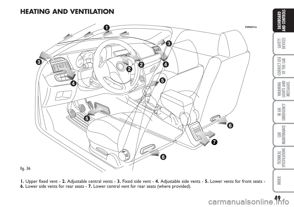
HEATING AND VENTILATION
1.Upper fixed vent - 2.Adjustable central vents - 3.Fixed side vent - 4.Adjustable side vents - 5. Lower vents for front seats -
6.Lower side vents for rear seats - 7.Lower central vent for rear seats (where provided).
Page 51 of 230
50
SAFETY
DEVICES
CORRECT USE
OF THE
CAR
WARNING
LIGHTS AND
MESSAGES
IN AN
EMERGENCY
CAR
MAINTENANCE
TECHNICAL
SPECIFICATIONS
INDEX
DASHBOARD
AND CONTROLS
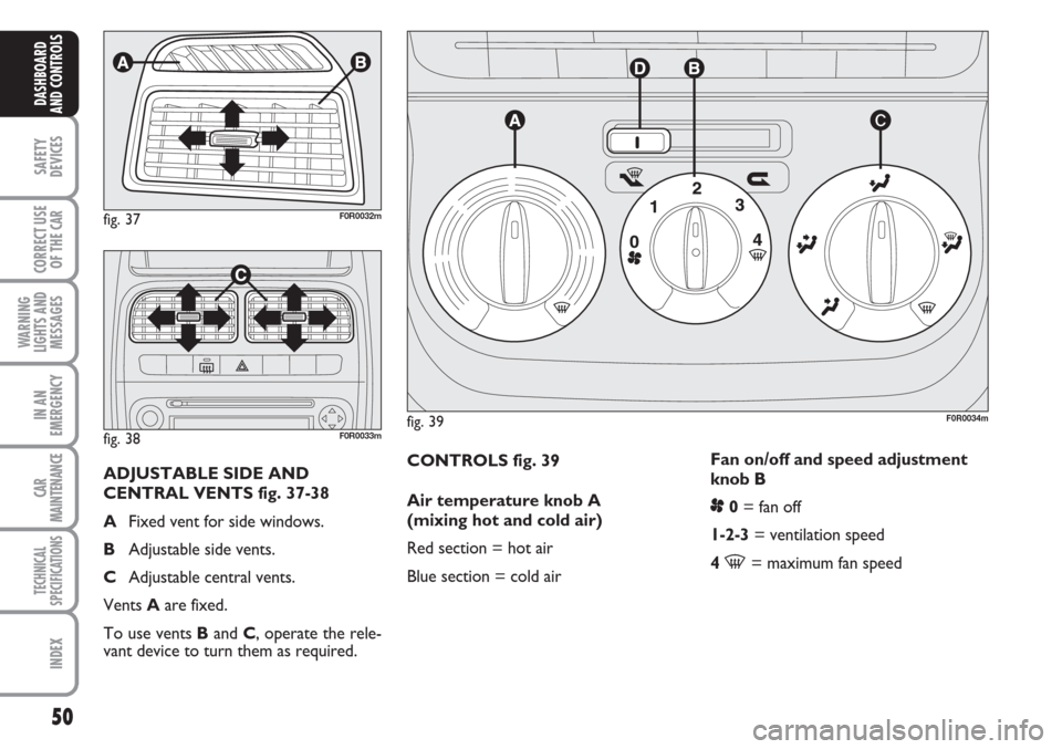
CONTROLS fig. 39
Air temperature knob A
(mixing hot and cold air)
Red section = hot air
Blue section = cold airFan on/off and speed adjustment
knob B
p0= fan off
1-2-3= ventilation speed
4
-= maximum fan speed
fig. 39F0R0034m
fig. 37F0R0032m
fig. 38F0R0033m
ADJUSTABLE SIDE AND
CENTRAL VENTS fig. 37-38
AFixed vent for side windows.
BAdjustable side vents.
CAdjustable central vents.
Vents Aare fixed.
To use vents Band C, operate the rele-
vant device to turn them as required.
Page 52 of 230
51
SAFETY
DEVICES
CORRECT USE
OF THE
CAR
WARNING
LIGHTS AND
MESSAGES
IN AN
EMERGENCY
CAR
MAINTENANCE
TECHNICAL
SPECIFICATIONS
INDEX
DASHBOARD
AND CONTROLS
Air distribution knob C
¶to convey air to the central and side
vents;
ßto warm the feet and convey cooler
air to the dashboard vents, in inter-
mediate temperature conditions;
©for heating when the outside temper-
ature is very cold: for maximum air
flow to feet;
®to warm the feet and demist the wind-
screen at the same time;
-for quick windscreen demisting.
Air recirculation on/off slider D
Take the slider to position
vto re-
circulate internal air.
Take the slider to position
¶to switch
internal air recirculation off.FAST HEATING
For fast heating of the passenger com-
partment, proceed as follows:
❒turn knob Ato the red sector;
❒switch internal air recirculation on;
❒turn knob Cto ¶;
❒knob Bturned to 4 -(max. fan
speed).
Then use the controls to keep the re-
quired comfort conditions and press but-
ton Dto
¶to turn air recirculation off
(button led off) and to prevent misting up.
IMPORTANT With cold engine, you have
to wait for a few minutes to let the sys-
tem fluid reach the operating temperature. VENTILATION
To ventilate the passenger’s compartment
properly proceed as follows:
❒knob Aturned to blue section;
❒switch internal air recirculation off;
❒turn knob Cto ¶;
❒turn knob Bto required speed.
WARMING THE PASSENGER
COMPARTMENT
Proceed as follows:
❒turn knob Ato the red sector;
❒turn knob Cto the required position;
❒turn knob Bto required speed.
Page 53 of 230
52
SAFETY
DEVICES
CORRECT USE
OF THE
CAR
WARNING
LIGHTS AND
MESSAGES
IN AN
EMERGENCY
CAR
MAINTENANCE
TECHNICAL
SPECIFICATIONS
INDEX
DASHBOARD
AND CONTROLS
FRONT WINDOW FAST
DEMISTING/
DEFROSTING (WINDSCREEN
AND SIDE WINDOWS)
Proceed as follows:
❒turn knob Ato the red sector;
❒switch internal air recirculation off;
❒turn knob Cto -;
❒knob Bturned to 4 -(max. fan
speed).
After demisting/defrosting, operate the
controls to restore the required comfort.Window demisting
In the event of considerable outside mois-
ture and/or rain and/or considerable dif-
ferences in temperature inside and outside
the passenger compartment, perform the
following preventive demisting procedure:
❒turn knob Ato the red sector;
❒switch internal air recirculation off;
❒turn knob Cto -. Change it to posi-
tion con
®if demisting is insufficient;
❒turn knob Bto 2ndspeed.HEATED REAR WINDOW
AND DOOR MIRROR
DEMISTING/DEFROSTING
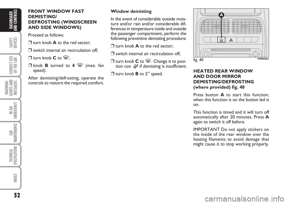
(where provided) fig. 40
Press button Ato start this function;
when this function is on the button led is
on.
This function is timed and it will turn off
automatically after 20 minutes. Press A
again to switch it off before.
IMPORTANT Do not apply stickers on
the inside of the rear window over the
heating filaments to avoid damage that
might cause it to stop working properly.
fig. 40F0R0035m
Page 54 of 230
53
SAFETY
DEVICES
CORRECT USE
OF THE
CAR
WARNING
LIGHTS AND
MESSAGES
IN AN
EMERGENCY
CAR
MAINTENANCE
TECHNICAL
SPECIFICATIONS
INDEX
DASHBOARD
AND CONTROLS
MANUAL CLIMATE
CONTROL SYSTEM
(where provided)
CONTROLS fig. 41
Air temperature knob A
(mixing hot and cold air)
Red section = hot air
Blue section = cold air
Fan activation /speed adjustment
knob B
p0= fan off
1-2-3= ventilation speed
4
-= maximum fan speed INTERNAL AIR
RECIRCULATION
Move slider Dto position vto switch
internal air recirculation on.
It is advisable to switch internal air recir-
culation on while standing in queues or in
tunnels to prevent the introduction of pol-
luted air. Do not use the function for a
long time, particularly if there are many
occupants on board, to prevent the win-
dows from misting up.IMPORTANT The inside air recirculation
system makes it possible to reach the re-
quired “heating” or “cooling” conditions
faster.
Do not use the air recirculation function
on rainy/cold days as it would consider-
ably increase the possibility of the win-
dows misting up.