technical specifications FIAT LINEA 2007 1.G Manual PDF
[x] Cancel search | Manufacturer: FIAT, Model Year: 2007, Model line: LINEA, Model: FIAT LINEA 2007 1.GPages: 230, PDF Size: 3.31 MB
Page 75 of 230
74
SAFETY
DEVICES
CORRECT USE
OF THE
CAR
WARNING
LIGHTS AND
MESSAGES
IN AN
EMERGENCY
CAR
MAINTENANCE
TECHNICAL
SPECIFICATIONS
INDEX
DASHBOARD
AND CONTROLS
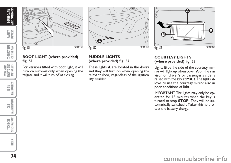
COURTESY LIGHTS
(where provided) fig. 53
Lights Bby the side of the courtesy mir-
ror will light up when cover Aon the sun
visor on driver’s or passenger’s side is
raised with the key at MAR. The lights al-
lows to use the courtesy mirror also in
poor conditions of light.
IMPORTANT The lights may only be op-
erated for 15 minutes when the key is
turned to stop STOP. They will be au-
tomatically switched off after this to pro-
tect the battery charge.
fig. 51F0R0044mfig. 53
B
B
A
F0R0216mfig. 52F0R0045m
BOOT LIGHT (where provided)
fig. 51
For versions fitted with boot light, it will
turn on automatically when opening the
tailgate and it will turn off at closing.PUDDLE LIGHTS
(where provided) fig. 52
These lights Aare located in the doors
and they will turn on when opening the
relevant door, regardless of the ignition
key position.
Page 76 of 230
75
SAFETY
DEVICES
CORRECT USE
OF THE
CAR
WARNING
LIGHTS AND
MESSAGES
IN AN
EMERGENCY
CAR
MAINTENANCE
TECHNICAL
SPECIFICATIONS
INDEX
DASHBOARD
AND CONTROLS
CONTROLS
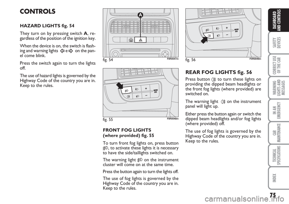
HAZARD LIGHTS fig. 54
They turn on by pressing switch A, re-
gardless of the position of the ignition key.
When the device is on, the switch is flash-
ing and warning lights
Îe ¥on the pan-
el come blink.
Press the switch again to turn the lights
off.
The use of hazard lights is governed by the
Highway Code of the country you are in.
Keep to the rules.
FRONT FOG LIGHTS
(where provided) fig. 55
To turn front fog lights on, press button
5, to activate these lights it is necessary
to have the side/taillights switched on.
The warning light
5on the instrument
cluster will come on at the same time.
Press the button again to turn the lights off.
The use of fog lights is governed by the
Highway Code of the country you are in.
Keep to the rules.
REAR FOG LIGHTS fig. 56
Press button 4to turn these lights on
providing the dipped beam headlights or
the front fog lights (where provided) are
switched on.
The warning light
4on the instrument
panel will light up.
Either press the button again or switch the
dipped beam headlights and/or fog lights
(where provided) off.
The use of fog lights is governed by the
Highway Code of the country you are in.
Keep to the rules.
fig. 54F0R0047m
fig. 55F0R0048m
fig. 56F0R0049m
Page 77 of 230
76
SAFETY
DEVICES
CORRECT USE
OF THE
CAR
WARNING
LIGHTS AND
MESSAGES
IN AN
EMERGENCY
CAR
MAINTENANCE
TECHNICAL
SPECIFICATIONS
INDEX
DASHBOARD
AND CONTROLS
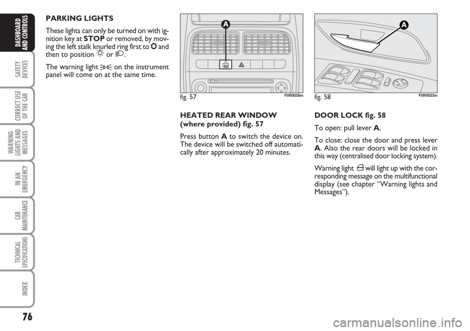
DOOR LOCK fig. 58
To open: pull lever A.
To close: close the door and press lever
A. Also the rear doors will be locked in
this way (centralised door locking system).
Warning light ´will light up with the cor-
responding message on the multifunctional
display (see chapter “Warning lights and
Messages”).
fig. 57F0R0035m
HEATED REAR WINDOW
(where provided) fig. 57
Press button Ato switch the device on.
The device will be switched off automati-
cally after approximately 20 minutes. PARKING LIGHTS
These lights can only be turned on with ig-
nition key at STOPor removed, by mov-
ing the left stalk knurled ring first to Oand
then to position
6or 2.
The warning light
3on the instrument
panel will come on at the same time.
fig. 58F0R0023m
Page 78 of 230
77
SAFETY
DEVICES
CORRECT USE
OF THE
CAR
WARNING
LIGHTS AND
MESSAGES
IN AN
EMERGENCY
CAR
MAINTENANCE
TECHNICAL
SPECIFICATIONS
INDEX
DASHBOARD
AND CONTROLS
Door unlocking in the event
of a crash
If the fuel cut-off switch trips following an
accident, the doors will be automatically
unlocked to let you leave the car and the
ceiling lights will be switched on at the
same time. The doors can always be
opened from the inside of the car by
means of the specific levers.
Proceed as follows if no fuel leakage is
found and and the car is in condition to be
driven to rearm the fuel cut-off switch.FUEL CUT-OFF SWITCH
The car is fitted with a safety switch that
in the event of a crash comes into opera-
tion by cutting off fuel and turning off the
engine as a consequence.
This device therefore prevents fuel leaks
due to fuel piping breaking.
IMPORTANT After the accident, re-
member to remove the electronic key
from the ignition device to prevent drain-
ing the battery.The message “FPS on” will appear on the
digital display when the switch trips. The
message “Inertia switch tripped. See hand-
book” will appear on the multifunctional
display.
If, after a crash, you smell fu-
el or see leaks from the fuel
system, do not reset the switch to
avoid fine risk.
WARNING
If the centralised door lock-
ing system was operated
from inside the car and the fuel cut-
off switch did not manage to auto-
matically release the doors, it will not
be possible to access the passenger
compartment from the outside after
an accident. The possibility of open-
ing the doors from the outside de-
pends on the conditions of the doors
themselves after the accident: if may
not be possible to open a damaged
door. In this case, try to open the oth-
er doors of the car.
WARNING
Page 79 of 230
78
SAFETY
DEVICES
CORRECT USE
OF THE
CAR
WARNING
LIGHTS AND
MESSAGES
IN AN
EMERGENCY
CAR
MAINTENANCE
TECHNICAL
SPECIFICATIONS
INDEX
DASHBOARD
AND CONTROLS
fig. 61F0R0077m
fig. 60F0R0104m
fig. 62F0R0078m
INTERIOR FITTINGS
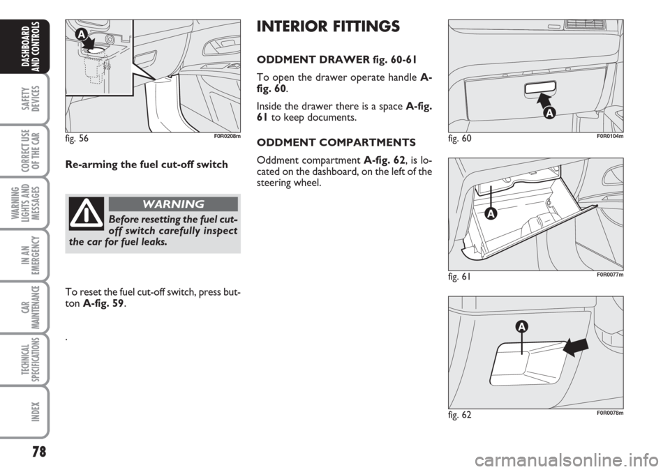
ODDMENT DRAWER fig. 60-61
To open the drawer operate handle A-
fig. 60.
Inside the drawer there is a space A-fig.
61to keep documents.
ODDMENT COMPARTMENTS
Oddment compartment A-fig. 62, is lo-
cated on the dashboard, on the left of the
steering wheel. Re-arming the fuel cut-off switch
Before resetting the fuel cut-
off switch carefully inspect
the car for fuel leaks.
WARNING
To reset the fuel cut-off switch, press but-
ton A-fig. 59.
.
fig. 56F0R0208m
Page 80 of 230
79
SAFETY
DEVICES
CORRECT USE
OF THE
CAR
WARNING
LIGHTS AND
MESSAGES
IN AN
EMERGENCY
CAR
MAINTENANCE
TECHNICAL
SPECIFICATIONS
INDEX
DASHBOARD
AND CONTROLS
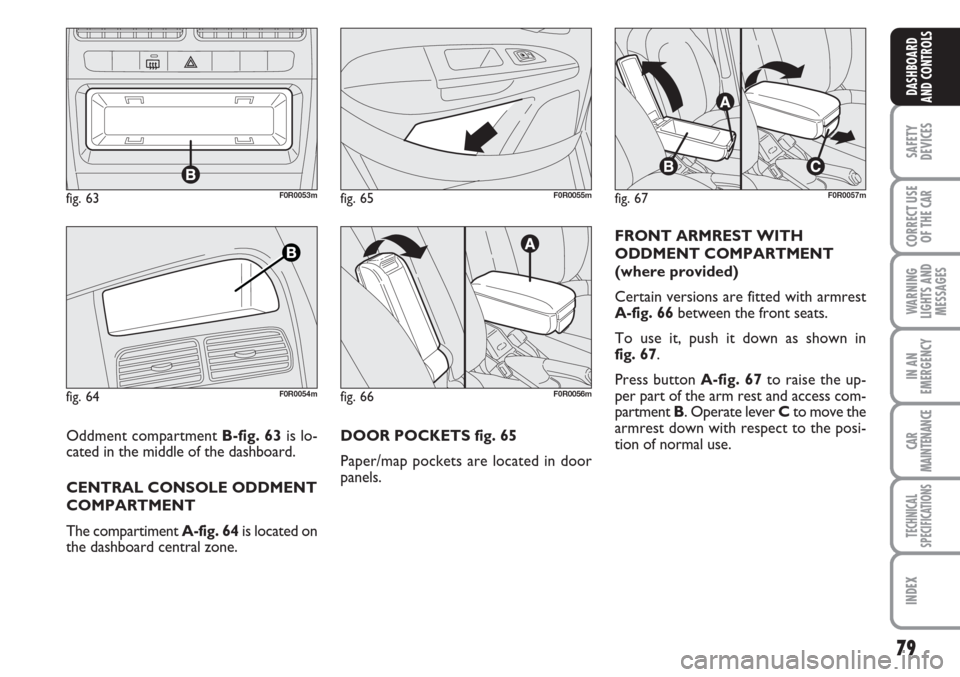
DOOR POCKETS fig. 65
Paper/map pockets are located in door
panels.FRONT ARMREST WITH
ODDMENT COMPARTMENT
(where provided)
Certain versions are fitted with armrest
A-fig. 66between the front seats.
To use it, push it down as shown in
fig. 67.
Press button A-fig. 67to raise the up-
per part of the arm rest and access com-
partment B. Operate lever Cto move the
armrest down with respect to the posi-
tion of normal use.
fig. 63F0R0053m
fig. 64F0R0054mfig. 66F0R0056m
fig. 67F0R0057mfig. 65F0R0055m
Oddment compartment B-fig. 63 is lo-
cated in the middle of the dashboard.
CENTRAL CONSOLE ODDMENT
COMPARTMENT
The compartiment A-fig. 64is located on
the dashboard central zone.
Page 81 of 230
80
SAFETY
DEVICES
CORRECT USE
OF THE
CAR
WARNING
LIGHTS AND
MESSAGES
IN AN
EMERGENCY
CAR
MAINTENANCE
TECHNICAL
SPECIFICATIONS
INDEX
DASHBOARD
AND CONTROLS
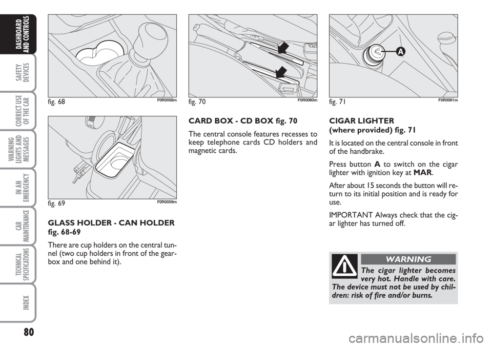
CIGAR LIGHTER
(where provided) fig. 71
It is located on the central console in front
of the handbrake.
Press button Ato switch on the cigar
lighter with ignition key at MAR.
After about 15 seconds the button will re-
turn to its initial position and is ready for
use.
IMPORTANT Always check that the cig-
ar lighter has turned off.
fig. 71F0R0061m
The cigar lighter becomes
very hot. Handle with care.
The device must not be used by chil-
dren: risk of fire and/or burns.
WARNING
GLASS HOLDER - CAN HOLDER
fig. 68-69
There are cup holders on the central tun-
nel (two cup holders in front of the gear-
box and one behind it). CARD BOX - CD BOX fig. 70
The central console features recesses to
keep telephone cards CD holders and
magnetic cards.
fig. 68F0R0058mfig. 70F0R0060m
fig. 69F0R0059m
Page 82 of 230
81
SAFETY
DEVICES
CORRECT USE
OF THE
CAR
WARNING
LIGHTS AND
MESSAGES
IN AN
EMERGENCY
CAR
MAINTENANCE
TECHNICAL
SPECIFICATIONS
INDEX
DASHBOARD
AND CONTROLS
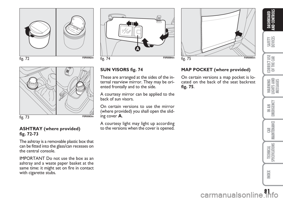
ASHTRAY (where provided)
fig. 72-73
The ashtray is a removable plastic box that
can be fitted into the glass/can recesses on
the central console.
IMPORTANT Do not use the box as an
ashtray and a waste paper basket at the
same time: it might set on fire in contact
with cigarette stubs.SUN VISORS fig. 74
These are arranged at the sides of the in-
ternal rearview mirror. They may be ori-
ented frontally and to the side.
A courtesy mirror can be applied to the
back of sun visors.
On certain versions to use the mirror
(where provided) you shall open the slid-
ing cover A.
A courtesy light may light up according
to the versions when the cover is opened.
fig. 72F0R0062mfig. 74F0R0064mfig. 75F0R0065m
fig. 73F0R0063m
MAP POCKET (where provided)
On certain versions a map pocket is lo-
cated on the back of the seat backrest
fig. 75.
Page 83 of 230
82
SAFETY
DEVICES
CORRECT USE
OF THE
CAR
WARNING
LIGHTS AND
MESSAGES
IN AN
EMERGENCY
CAR
MAINTENANCE
TECHNICAL
SPECIFICATIONS
INDEX
DASHBOARD
AND CONTROLS
DOORS
CENTRAL DOOR
LOCKING/UNLOCKING SYSTEM
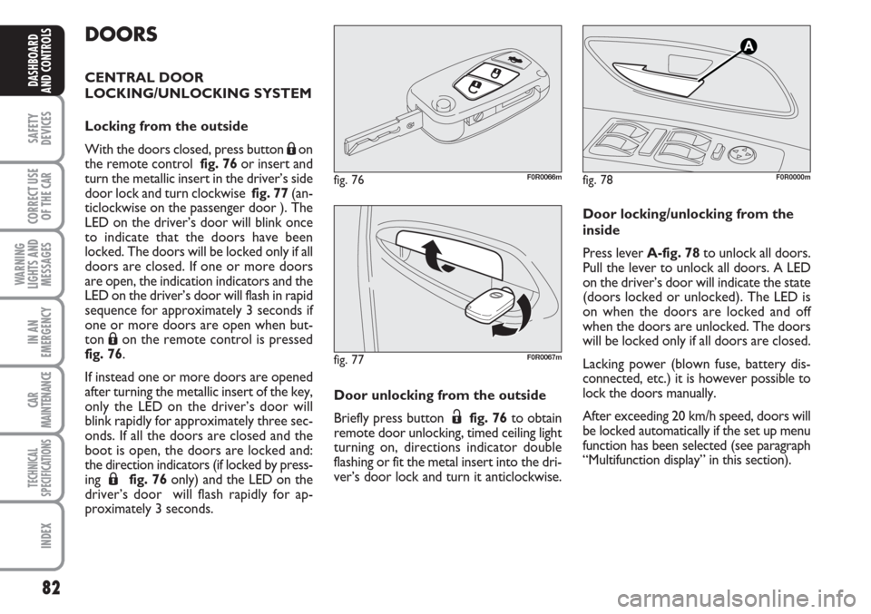
Locking from the outside
With the doors closed, press button
Áon
the remote control fig. 76or insert and
turn the metallic insert in the driver’s side
door lock and turn clockwise fig. 77(an-
ticlockwise on the passenger door ). The
LED on the driver’s door will blink once
to indicate that the doors have been
locked. The doors will be locked only if all
doors are closed. If one or more doors
are open, the indication indicators and the
LED on the driver’s door will flash in rapid
sequence for approximately 3 seconds if
one or more doors are open when but-
ton
Áon the remote control is pressed
fig. 76.
If instead one or more doors are opened
after turning the metallic insert of the key,
only the LED on the driver’s door will
blink rapidly for approximately three sec-
onds. If all the doors are closed and the
boot is open, the doors are locked and:
the direction indicators (if locked by press-
ing
Áfig. 76only) and the LED on the
driver’s door will flash rapidly for ap-
proximately 3 seconds.Door unlocking from the outside
Briefly press button
Ëfig. 76to obtain
remote door unlocking, timed ceiling light
turning on, directions indicator double
flashing or fit the metal insert into the dri-
ver’s door lock and turn it anticlockwise.
fig. 77F0R0067m
fig. 78F0R0000m
Door locking/unlocking from the
inside
Press lever A-fig. 78to unlock all doors.
Pull the lever to unlock all doors. A LED
on the driver’s door will indicate the state
(doors locked or unlocked). The LED is
on when the doors are locked and off
when the doors are unlocked. The doors
will be locked only if all doors are closed.
Lacking power (blown fuse, battery dis-
connected, etc.) it is however possible to
lock the doors manually.
After exceeding 20 km/h speed, doors will
be locked automatically if the set up menu
function has been selected (see paragraph
“Multifunction display” in this section).
fig. 76F0R0066m
Page 84 of 230
83
SAFETY
DEVICES
CORRECT USE
OF THE
CAR
WARNING
LIGHTS AND
MESSAGES
IN AN
EMERGENCY
CAR
MAINTENANCE
TECHNICAL
SPECIFICATIONS
INDEX
DASHBOARD
AND CONTROLS
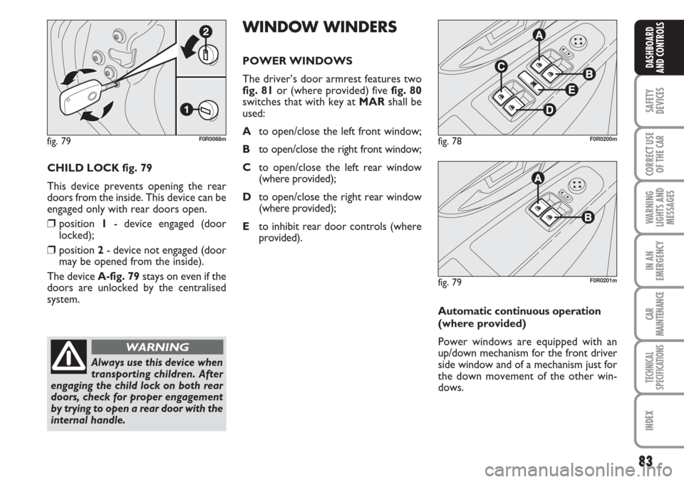
CHILD LOCK fig. 79
This device prevents opening the rear
doors from the inside. This device can be
engaged only with rear doors open.
❒position 1- device engaged (door
locked);
❒position 2- device not engaged (door
may be opened from the inside).
The device A-fig. 79stays on even if the
doors are unlocked by the centralised
system.
fig. 79F0R0068m
Always use this device when
transporting children. After
engaging the child lock on both rear
doors, check for proper engagement
by trying to open a rear door with the
internal handle.
WARNING
WINDOW WINDERS
POWER WINDOWS
The driver’s door armrest features two
fig. 81or (where provided) five fig. 80
switches that with key at MARshall be
used:
Ato open/close the left front window;
Bto open/close the right front window;
Cto open/close the left rear window
(where provided);
Dto open/close the right rear window
(where provided);
Eto inhibit rear door controls (where
provided).
fig. 78F0R0200m
fig. 79F0R0201m
Automatic continuous operation
(where provided)
Power windows are equipped with an
up/down mechanism for the front driver
side window and of a mechanism just for
the down movement of the other win-
dows.