technical specifications FIAT MULTIPLA 2006 1.G Owners Manual
[x] Cancel search | Manufacturer: FIAT, Model Year: 2006, Model line: MULTIPLA, Model: FIAT MULTIPLA 2006 1.GPages: 266, PDF Size: 4.61 MB
Page 145 of 266
144
WARNING
LIGHTS AND
MESSAGES
IN AN
EMERGENCY
CAR
MAINTENANCE
TECHNICAL
SPECIFICATIONS
INDEX
DASHBOARD
AND CONTROLS
SAFETY
DEVICES
CORRECT USE
OF THE CAR
DRIVING STYLE
Starting
Do not warm the engine with the car at a standstill or
at idle or high speed: under these conditions the
engine warms up much more slowly, increasing
electrical consumption and emissions. It is therefore
advisable to move off immediately, slowly, avoiding
high speeds. This way the engine will warm faster.
Unnecessary actions
Avoid accelerating when waiting at traffic lights or
before switching off the engine. This and also double
declutching is absolutely pointless on modern cars and
also increase consumption and pollution.
Gear selection
As soon as the conditions of the traffic and road allow,
use a higher gear. Using a low gear to obtain brilliant
performance increases consumption.
In the same way improper use of a high gear increases
consumption, emissions an engine wear.
Top speed
Fuel consumption considerably increases with speed.
Keep speed as constant as possible and avoid
superfluous braking and accelerating, which cost in
terms of both fuel and emissions.Acceleration
Accelerating violently increasing the revs will greatly
affect consumption and emissions: acceleration should
be gradual and should not exceed the maximum
torque.
CONDITIONS OF USE
Cold starting
Short journeys and frequent cold starts do not allow
the engine to reach optimum operating temperature.
This results in a significant increase in consumption
levels (from +15 to +30% on the urban cycle) and
emission of harmful substances.
Traffic situations and road conditions
Rather high consumption levels are tied to situations
with heavy traffic, for example in queues with frequent
use of the lower gears or in cities with many traffic
lights. Also winding mountain roads and rough road
surfaces adversely affect consumption.
Traffic hold-ups
During prolonged hold-ups (e.g. level crossings) the
engine should be switched off.
Page 146 of 266
145
WARNING
LIGHTS AND
MESSAGES
IN AN
EMERGENCY
CAR
MAINTENANCE
TECHNICAL
SPECIFICATIONS
INDEX
DASHBOARD
AND CONTROLS
SAFETY
DEVICES
CORRECT USE
OF THE CAR
TOWING TRAILERS
IMPORTANT NOTES
For towing caravans or trailers the car must be fitted
with a certified tow hook and an adequate electric
system. Installation should be carried out by
specialised personnel who release a special document
for circulation on the road.
Install any specific and/or additional rear-view mirrors
in accordance with the Highway Code.
Remember that when towing a trailer, steep hills are
harder to climb, the braking spaces increase and
overtaking takes longer depending on the overall
weight.Engage a low gear when driving downhill, rather than
constantly using the brake.
The weight the trailer exerts on the car tow hook
reduces by the same amount the actual vehicle loading
capacity.
To make sure the maximum towable weight is not
exceeded, account should be taken of the fully laden
trailer, including accessories and personal belongings.
Do not exceed the speed limits of the country you are
driving in. In any case do not exceed 100 km/h.
WARNINGThe ABS system with which the car may be fitted does not control the trailer
braking system.
Under no circumstances should the vehicle brake system be altered to control the
trailer brake. The trailer braking system must be fully independent of the vehicle’s
hydraulic system.WARNING
Page 147 of 266
146
WARNING
LIGHTS AND
MESSAGES
IN AN
EMERGENCY
CAR
MAINTENANCE
TECHNICAL
SPECIFICATIONS
INDEX
DASHBOARD
AND CONTROLS
SAFETY
DEVICES
CORRECT USE
OF THE CAR
INSTALLING THE TOW HOOK
The towing device should be fastened to the body by
specialised personnel according to any additional
and/or integrative information supplied by the
Manufacturer of the device.
Have installation carried out at Fiat Dealership.
The towing device must meet current regulations with
reference to 94/20/EC Directive and subsequent
amendments.
For any version the towing device used must match
the towable weight of the car on which it is to be
installed.
For the electric connection a unified connector should
be used which is generally placed on a special bracket
normally fastened to the towing device, and a special
ECU for external trailer light control shall be installed
on the car.
When fitting the trailer, parking sensors are
deactivated.For the electrical connection, a 7 pin 12VDC
connection is to be used (CUNA/UNI and ISO/DIN
Standards). Follow the instructions provided by the car
manufacturer and/or the tow hitch manufacturer.
An electric brake should be supplied directly by the
battery through a cable with a cross section of no less
than 2.5 mm
2.
IMPORTANT Electric brake or other device shall be
used with running engine.
In addition to the electrical branches, the car’s electric
system can only be connected to the supply cable for
an electric brake and to the cable for an internal light,
though not above 15W.
For connections, use the preset control unit with
battery cable no less than 2.5 mm
2.
The two hitches are shown on the following pages.
Page 148 of 266
147
WARNING
LIGHTS AND
MESSAGES
IN AN
EMERGENCY
CAR
MAINTENANCE
TECHNICAL
SPECIFICATIONS
INDEX
DASHBOARD
AND CONTROLS
SAFETY
DEVICES
CORRECT USE
OF THE CAR
F0E0192m
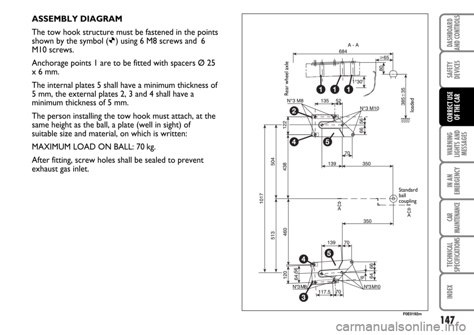
ASSEMBLY DIAGRAM
The tow hook structure must be fastened in the points
shown by the symbol (
Ø) using 6 M8 screws and 6
M10 screws.
Anchorage points 1 are to be fitted with spacers Ø 25
x 6 mm.
The internal plates 5 shall have a minimum thickness of
5 mm, the external plates 2, 3 and 4 shall have a
minimum thickness of 5 mm.
The person installing the tow hook must attach, at the
same height as the ball, a plate (well in sight) of
suitable size and material, on which is written:
MAXIMUM LOAD ON BALL: 70 kg.
After fitting, screw holes shall be sealed to prevent
exhaust gas inlet.
Rear wheel axle
loaded
Standard
ball
coupling
Page 149 of 266
148
WARNING
LIGHTS AND
MESSAGES
IN AN
EMERGENCY
CAR
MAINTENANCE
TECHNICAL
SPECIFICATIONS
INDEX
DASHBOARD
AND CONTROLS
SAFETY
DEVICES
CORRECT USE
OF THE CAR
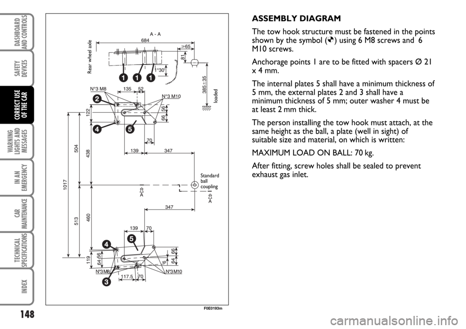
ASSEMBLY DIAGRAM
The tow hook structure must be fastened in the points
shown by the symbol (
Ø) using 6 M8 screws and 6
M10 screws.
Anchorage points 1 are to be fitted with spacers Ø 21
x 4 mm.
The internal plates 5 shall have a minimum thickness of
5 mm, the external plates 2 and 3 shall have a
minimum thickness of 5 mm; outer washer 4 must be
at least 2 mm thick.
The person installing the tow hook must attach, at the
same height as the ball, a plate (well in sight) of
suitable size and material, on which is written:
MAXIMUM LOAD ON BALL: 70 kg.
After fitting, screw holes shall be sealed to prevent
exhaust gas inlet.
F0E0193m
Rear wheel axle
loaded
Standard
ball
coupling
Page 150 of 266
149
WARNING
LIGHTS AND
MESSAGES
IN AN
EMERGENCY
CAR
MAINTENANCE
TECHNICAL
SPECIFICATIONS
INDEX
DASHBOARD
AND CONTROLS
SAFETY
DEVICES
CORRECT USE
OF THE CAR
SNOW TYRES
These tyres have been specially designed for driving on
snow or ice, to be fitted in place of the standard tyres.
Use snow tyres of the same size as the standard tyres
provided with the car.
Fiat Dealership will be happy to provide advice
concerning the most suitable type of tyre for the
customer’s requirements.
For the type of tyre to be used, inflation pressures and
the specifications of snow tyres, follow the
instructions given in paragraph “Wheels” in section
“Technical specifications”.
The winter features of these tyres are reduced
considerably when the tread depth is below 4 mm. In
this case, they should be replaced.
Due to the snow tyre features, under normal
conditions of use or on long motorway journeys, the
performance of these tyres is lower than that of
standard tyres.It is therefore necessary to limit their use to the
purposes for which they are certified.
IMPORTANT When snow tyres are used with a max
speed index below the one that can be reached by the
car (increased by 5%), place a notice in the passenger
compartment, plainly in the driver’s view which states
the max permissible speed of the snow tyres (as per
EC Directive).
All four tyres should be the same (brand and track) to
ensure greater safety when driving and braking and
better driveability.
Remember that it is inappropriate to change the
direction of rotation of tyres.
The max speed for snow tyres with “Q” marking is 160 km/h. The Road Traffic
Code speed limits must however be always strictly observed.WARNING
Page 151 of 266
150
WARNING
LIGHTS AND
MESSAGES
IN AN
EMERGENCY
CAR
MAINTENANCE
TECHNICAL
SPECIFICATIONS
INDEX
DASHBOARD
AND CONTROLS
SAFETY
DEVICES
CORRECT USE
OF THE CAR
SNOW CHAINS
Use of snow chains should be in compliance with local
regulations.
Snow chains should only be applied to the driving
wheels (front wheels).
Check the tension of the chains after the first few
metres have been driven.
IMPORTANT Snow chains cannot be fitted to the
space-saver spare wheel. So, if a front (drive) wheel is
punctured and chains are needed, a rear wheel should
be fitted to the front of the vehicle and the spare
wheel should be fitted to the rear. This way with two
normal drive wheels, snow chains can be fitted to
them to solve an emergency.Tyres on which chains can be fitted:
– 185/65 R 15 88H
– 195/60 R 15 88H
Use slow profile snow chains with maximum height off
the tyre of 10 mm.
Keep your speed down when snow chains are fitted. Do not exceed 50 Km/h. Avoid potholes, steps
and pavements and avoid also to drive for long distances on roads not covered with snow to
prevent damaging the car and the roadbed.
Page 152 of 266
151
WARNING
LIGHTS AND
MESSAGES
IN AN
EMERGENCY
CAR
MAINTENANCE
TECHNICAL
SPECIFICATIONS
INDEX
DASHBOARD
AND CONTROLS
SAFETY
DEVICES
CORRECT USE
OF THE CAR
STORING THE CAR
If the car is to be left inactive for longer than a month,
the following precautions should be noted:
❒Park the car in covered, dry and if possible well-
ventilated premises.
❒Engage a gear.
❒Check that the handbrake is not engaged.
❒Disconnect battery terminals (first disconnect the
negative terminal) and check the battery charge.
This check is to be repeated every month, recharge
if battery charge falls below 12.5V.
IMPORTANT Where relevant, switch off the
electronic car alarm with the remote control.❒Clean and protect the painted parts using protective
wax.
❒Clean and protect the shiny metal parts using special
compounds readily available.
❒Sprinkle talcum powder on the rubber windscreen
and rear window wiper blades and lift them off the
glass.
❒Slightly open the windows.
❒Cover the car with a cloth or perforated plastic
sheet. Do not use sheets of non-perforated plastic
as they do not allow moisture on the car body to
evaporate.
❒Inflate tyres to +0.5 bar above the normal specified
pressure and check it at intervals.
❒Do not drain the engine cooling system.
Page 153 of 266
152
IN AN
EMERGENCY
CAR
MAINTENANCE
TECHNICAL
SPECIFICATIONS
INDEX
DASHBOARD
AND CONTROLS
SAFETY
DEVICES
CORRECT USE
OF THE CAR
WARNING
LIGHTS AND
MESSAGES
152
W W
A A
R R
N N
I I
N N
G G
L L
I I
G G
H H
T T
S S
A A
N N
D D
M M
E E
S S
S S
A A
G G
E E
S S
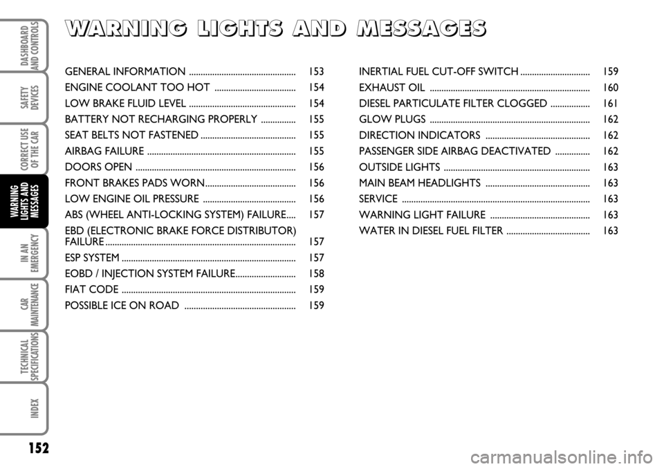
GENERAL INFORMATION .............................................. 153
ENGINE COOLANT TOO HOT ................................... 154
LOW BRAKE FLUID LEVEL .............................................. 154
BATTERY NOT RECHARGING PROPERLY ............... 155
SEAT BELTS NOT FASTENED ......................................... 155
AIRBAG FAILURE ................................................................ 155
DOORS OPEN ..................................................................... 156
FRONT BRAKES PADS WORN....................................... 156
LOW ENGINE OIL PRESSURE ........................................ 156
ABS (WHEEL ANTI-LOCKING SYSTEM) FAILURE.... 157
EBD (ELECTRONIC BRAKE FORCE DISTRIBUTOR)
FAILURE .................................................................................. 157
ESP SYSTEM ........................................................................... 157
EOBD / INJECTION SYSTEM FAILURE.......................... 158
FIAT CODE ........................................................................... 159
POSSIBLE ICE ON ROAD ................................................ 159INERTIAL FUEL CUT-OFF SWITCH .............................. 159
EXHAUST OIL ..................................................................... 160
DIESEL PARTICULATE FILTER CLOGGED ................. 161
GLOW PLUGS ..................................................................... 162
DIRECTION INDICATORS ............................................. 162
PASSENGER SIDE AIRBAG DEACTIVATED ............... 162
OUTSIDE LIGHTS ............................................................... 163
MAIN BEAM HEADLIGHTS ............................................. 163
SERVICE ................................................................................. 163
WARNING LIGHT FAILURE ........................................... 163
WATER IN DIESEL FUEL FILTER .................................... 163
Page 154 of 266
153
CORRECT USE
OF THE CAR
IN AN
EMERGENCY
CAR
MAINTENANCE
TECHNICAL
SPECIFICATIONS
INDEX
DASHBOARD
AND CONTROLS
SAFETY
DEVICES
WARNING
LIGHTS AND
MESSAGES
153
GENERAL INFORMATION
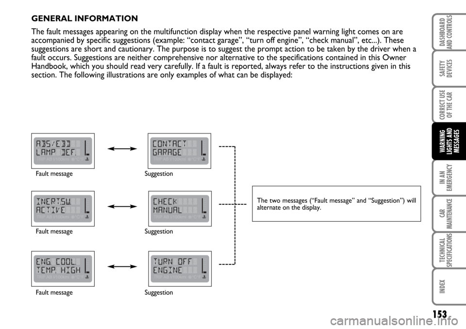
The fault messages appearing on the multifunction display when the respective panel warning light comes on are
accompanied by specific suggestions (example: “contact garage”, “turn off engine”, “check manual”, etc...). These
suggestions are short and cautionary. The purpose is to suggest the prompt action to be taken by the driver when a
fault occurs. Suggestions are neither comprehensive nor alternative to the specifications contained in this Owner
Handbook, which you should read very carefully. If a fault is reported, always refer to the instructions given in this
section. The following illustrations are only examples of what can be displayed:
Fault message
Fault message
Fault messageSuggestion
Suggestion
Suggestion
The two messages (“Fault message” and “Suggestion”) will
alternate on the display.