technical specifications FIAT MULTIPLA 2006 1.G Owners Manual
[x] Cancel search | Manufacturer: FIAT, Model Year: 2006, Model line: MULTIPLA, Model: FIAT MULTIPLA 2006 1.GPages: 266, PDF Size: 4.61 MB
Page 165 of 266
164
SAFETY
DEVICES
CORRECT USE
OF THE CAR
WARNING
LIGHTS AND
MESSAGES
CAR
MAINTENANCE
TECHNICAL
SPECIFICATIONS
INDEX
DASHBOARD
AND CONTROLS
IN AN
EMERGENCY
I I
N N
A A
N N
E E
M M
E E
R R
G G
E E
N N
C C
Y Y
ENGINE STARTING .................................................. 165
IF A TYRE IS PUNCTURED ..................................... 167
QUICK TYRE REPAIR KIT
FIX & GO AUTOMATIC .......................................... 177
IF A BULB BURNS OUT ........................................... 183
IF AN EXTERIOR LIGHT BURNS OUT ............... 186
IF AN INTERIOR LIGHT BURNS OUT ............... 192
IF A FUSE BLOWS ..................................................... 194
IF THE BATTERY IS FLAT ........................................ 202
JACKING THE CAR .................................................. 203
TOWING THE CAR ................................................. 203
Page 166 of 266

165
SAFETY
DEVICES
CORRECT USE
OF THE CAR
WARNING
LIGHTS AND
MESSAGES
CAR
MAINTENANCE
TECHNICAL
SPECIFICATIONS
INDEX
DASHBOARD
AND CONTROLS
IN AN
EMERGENCY
ENGINE STARTING
EMERGENCY START-UP
If the Fiat Code system cannot deactivate the engine
immobiliser, the warning lights
¢and Uwill remain
lit and the engine will not start. To start your car
follow the emergency start-up procedure.
Read the whole procedure carefully before trying to
carry it out. If you make a mistake, you must turn the
ignition key back to STOP and repeat the whole
operation from beginning (step 1).
❒Read the 5-figure electronic code given on the
CODE card.
❒Turn the ignition key to MAR.
❒Press and hold down the accelerator pedal. The
warning light
Uturns on for about 8 seconds, and
then goes off; release the accelerator pedal and get
ready to count the flashes of the
Uwarning light.
❒Count the number of flashes that corresponds to
the first figure of the code on the CODE card, then
press the accelerator pedal and keep it there until
the
Uwarning light comes on (for 4 seconds) and
then goes off; release the accelerator pedal.❒The warning light
Uwill start flashing again: after it
has flashed the number of times that corresponds to
the second figure on the CODE card, press the
accelerator pedal to the floor and keep it there.
❒Do the same for the remaining figures on the
CODE card.
❒Once the final figure has been entered, keep the
accelerator pedal pressed. The warning light
Uwill
light up for 4 seconds and then go out; release the
accelerator pedal.
❒Rapid flashing of the warning light
U(for about 4
seconds) confirms the operation has been carried
out successfully.
❒Start the engine by turning the ignition key from
MAR to AVV.
If however the warning light
Ustays on, turn the
ignition key to STOP and repeat the procedure from
step 1.
IMPORTANT After an emergency start-up, you should
contact a Fiat Dealership otherwise you will have to
repeat the procedure described each time you want to
start the engine.
Page 167 of 266
166
SAFETY
DEVICES
CORRECT USE
OF THE CAR
WARNING
LIGHTS AND
MESSAGES
CAR
MAINTENANCE
TECHNICAL
SPECIFICATIONS
INDEX
DASHBOARD
AND CONTROLS
IN AN
EMERGENCY
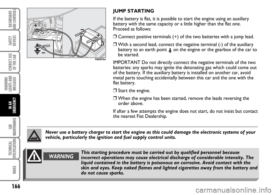
JUMP STARTING
If the battery is flat, it is possible to start the engine using an auxiliary
battery with the same capacity or a little higher than the flat one.
Proceed as follows:
❒Connect positive terminals (+) of the two batteries with a jump lead.
❒With a second lead, connect the negative terminal (-) of the auxiliary
battery to an earth point
Eon the engine or the gearbox of the car to
be started.
IMPORTANT Do not directly connect the negative terminals of the two
batteries: any sparks may ignite the detonating gas which could come out
of the battery. If the auxiliary battery is installed on another car, avoid
metal parts touching accidentally between this car and the one with the
flat battery.
❒Start the engine.
❒When the engine has been started, remove the leads reversing the
order above.
If after a few attempts the engine does not start, do not insist but contact
the nearest Fiat Dealership.
F0E0670m
Never use a battery charger to start the engine as this could damage the electronic systems of your
vehicle, particularly the ignition and fuel supply control units.
WARNINGThis starting procedure must be carried out by qualified personnel because
incorrect operations may cause electrical discharge of considerable intensity. The
liquid contained in the battery is poisonous an corrosive. Avoid contact with the
skin and eyes. Keep naked flames and lighted cigarettes away from the battery and
do not cause sparks.
Page 168 of 266
167
SAFETY
DEVICES
CORRECT USE
OF THE CAR
WARNING
LIGHTS AND
MESSAGES
CAR
MAINTENANCE
TECHNICAL
SPECIFICATIONS
INDEX
DASHBOARD
AND CONTROLS
IN AN
EMERGENCY
BUMP STARTING
Never bump start the engine by pushing, towing or
coasting downhill.
This could cause fuel to flow into the catalytic
converter and damage it beyond repair.
IMPORTANT Remember that the servobrake and
electrical power steering system are not operating
until the engine is started, a greater effort will
therefore be required to press the brake pedal or turn
the steering wheel.IF A TYRE IS PUNCTURED
GENERAL INSTRUCTIONS
For versions/markets where applicable, the car can be
fitted with a quick tyre repair kit called FIX & GO,
replacing the usual tool fitting, the spare wheel lifting
winch and the space-saver spare wheel.
Normal spare small wheel, or (where provided)
normal size spare wheel, can be supplied on request;
for its use, follow what indicated below.
VAN versions are fitted as standard with a spare
wheel with steel rim of the same type and size as the
standard wheels mounted on the car.
Wheel changing and correct use of the jack and space-
saver spare wheel call for some precautions as listed
below.
WARNINGAlert other drivers that the car is stationary in compliance with local regulations:
hazard warning lights, warning triangle, etc. Any passengers on board should leave the
car, especially if it is heavily laden. Passengers should stay away from oncoming traffic
while the wheel is being changed. If parked on a slope or rough surface, chock the
wheels with wedges or other suitable devices to prevent the car from rolling.
Page 169 of 266
168
SAFETY
DEVICES
CORRECT USE
OF THE CAR
WARNING
LIGHTS AND
MESSAGES
CAR
MAINTENANCE
TECHNICAL
SPECIFICATIONS
INDEX
DASHBOARD
AND CONTROLS
IN AN
EMERGENCY
WARNINGThe space-saver spare wheel (where provided) is specific to your car, do not use it
on other models, or use the spare wheel of other models on your vehicle. The
space-saver spare wheel shall only be used in an emergency. It shall only be used
for the distance necessary to reach a service point and the car speed shall not
exceed 80 km/h. The spare wheel has an orange sticker that summarises the main
cautions for use and limitations. The sticker should never be removed or covered.
Never fit a wheel cap on a space-saver spare wheel. The sticker gives the following
information in four languages: caution! For temporary use only! 80 km/h max!
Replace by normal wheel as soon as possible. Do not cover this label in use.
If changing standard wheels (e.g.: wheels with alloy rims in place of steel rims)
change also all wheel bolts.
WARNINGWhen driving with a space-saver spare wheel fitted, the driving performance of the
car changes. Avoid accelerating or braking sharply, abrupt turns or fast cornerings.
The life of the spare wheel is approx. 3000 km, after this distance it should be
replaced with another of the same type. Never attempt to fit a conventional tyre
on a rim designed for use as a space-saver spare wheel. Have the punctured wheel
repaired and refitted as soon as possible. Two or more space-saver spare wheels
should never be used together. Do not grease the threads of bolts before installing
them: they might slip out.
Page 170 of 266
169
SAFETY
DEVICES
CORRECT USE
OF THE CAR
WARNING
LIGHTS AND
MESSAGES
CAR
MAINTENANCE
TECHNICAL
SPECIFICATIONS
INDEX
DASHBOARD
AND CONTROLS
IN AN
EMERGENCY
WARNINGThe jack shall only be used for changing wheels on the car with which it is provided
or on cars of the same model. It must not be used for other purposes such as for
instance raising cars of other models. In no case should it be used for repairs under
the car. Incorrect positioning of the jack may cause the jacked vehicle to fall. Do
not use the jack for higher capacities than stated on its label. Snow chains cannot
be fitted to the space-saver spare wheel. So, if a front (drive) wheel is punctured
and chains are needed, a rear wheel should be fitted to the front of the vehicle and
the spare wheel should be fitted to the rear. This way with two normal drive
wheels, snow chains can be fitted to them to solve an emergency.
ATTENZIONEFasten the wheel cap correctly to prevent the wheel from coming free in motion.
Never tamper with the inflation valve. Never place tools between the rim and tyre.
Check and restore, if required, the pressure of tyres and spare wheel to the values
given in the “Technical specifications” section.
Page 171 of 266
170
SAFETY
DEVICES
CORRECT USE
OF THE CAR
WARNING
LIGHTS AND
MESSAGES
CAR
MAINTENANCE
TECHNICAL
SPECIFICATIONS
INDEX
DASHBOARD
AND CONTROLS
IN AN
EMERGENCY
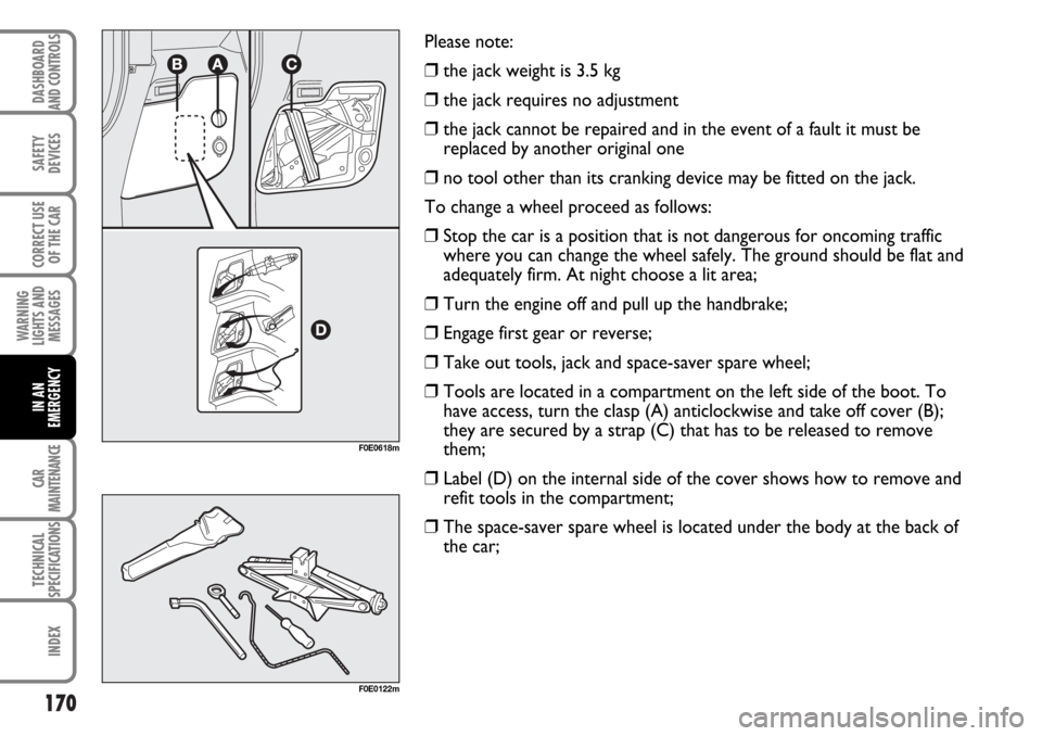
Please note:
❒the jack weight is 3.5 kg
❒the jack requires no adjustment
❒the jack cannot be repaired and in the event of a fault it must be
replaced by another original one
❒no tool other than its cranking device may be fitted on the jack.
To change a wheel proceed as follows:
❒Stop the car is a position that is not dangerous for oncoming traffic
where you can change the wheel safely. The ground should be flat and
adequately firm. At night choose a lit area;
❒Turn the engine off and pull up the handbrake;
❒Engage first gear or reverse;
❒Take out tools, jack and space-saver spare wheel;
❒Tools are located in a compartment on the left side of the boot. To
have access, turn the clasp (A) anticlockwise and take off cover (B);
they are secured by a strap (C) that has to be released to remove
them;
❒Label (D) on the internal side of the cover shows how to remove and
refit tools in the compartment;
❒The space-saver spare wheel is located under the body at the back of
the car;
F0E0618m
F0E0122m
Page 172 of 266
171
SAFETY
DEVICES
CORRECT USE
OF THE CAR
WARNING
LIGHTS AND
MESSAGES
CAR
MAINTENANCE
TECHNICAL
SPECIFICATIONS
INDEX
DASHBOARD
AND CONTROLS
IN AN
EMERGENCY
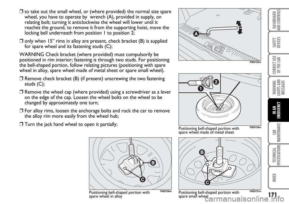
❒to take out the small wheel, or (where provided) the normal size spare
wheel, you have to operate by wrench (A), provided in supply, on
relating bolt; turning it anticlockwise the wheel will lower until it
reaches the ground, to remove it from the supporting hoist, move the
locking bell underneath from position 1 to position 2;
❒only when 15” rims in alloy are present, check bracket (B) is supplied
for spare wheel and its fastening studs (C);
WARNING Check bracket (where provided) must compulsorily be
positioned in rim interior; fastening is through two studs. For positioning
the bell-shaped portion, follow relating pictures (positioning with spare
wheel in alloy, spare wheel made of metal sheet or spare small wheel).
❒Remove check bracket (B) (if present) unscrewing the two fastening
studs (C);
❒Remove the wheel cap (where provided) using a screwdriver as a lever
on the edge of the cap. Loosen the wheel bolts on the wheel to be
changed by approximately one turn;
❒For alloy rims, loosen the anchorage bolts and rock the car to remove
the alloy rim more easily from the wheel hub;
❒Turn the jack hand wheel to open it partially;
F0E0123m
F0E0124m
F0E0727mF0E0726m
Positioning bell-shaped portion with
spare wheel made of metal sheet
Positioning bell-shaped portion with
spare small wheel Positioning bell-shaped portion with
spare wheel in alloy
Page 173 of 266
172
SAFETY
DEVICES
CORRECT USE
OF THE CAR
WARNING
LIGHTS AND
MESSAGES
CAR
MAINTENANCE
TECHNICAL
SPECIFICATIONS
INDEX
DASHBOARD
AND CONTROLS
IN AN
EMERGENCY
F0E0672m
F0E0127m
F0E0671m
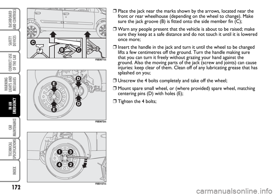
❒Place the jack near the marks shown by the arrows, located near the
front or rear wheelhouse (depending on the wheel to change). Make
sure the jack groove (B) is fitted onto the side member fin (C);
❒Warn any people present that the vehicle is about to be raised; make
sure they keep at a safe distance and do not touch it until it is lowered
once more;
❒Insert the handle in the jack and turn it until the wheel to be changed
lifts a few centimetres off the ground. Turn the handle making sure
that you can turn it freely without grazing your hand against the
ground. Also the moving parts of the jack (screw and joints) can cause
injuries: keep clear of them. Clean off of any lubricating grease that has
splashed on you;
❒Unscrew the 4 bolts completely and take off the wheel;
❒Mount spare small wheel, or (where provided) spare wheel, matching
centering pins (D) with holes (E);
❒Tighten the 4 bolts;
Page 174 of 266
173
SAFETY
DEVICES
CORRECT USE
OF THE CAR
WARNING
LIGHTS AND
MESSAGES
CAR
MAINTENANCE
TECHNICAL
SPECIFICATIONS
INDEX
DASHBOARD
AND CONTROLS
IN AN
EMERGENCY
WARNINGOnce the procedure has been
terminated, always check wheel correct
locking. ❒Turn the jack handle to lower the car and remove the jack;
❒Tighten up the wheel bolts completely in criss-cross fashion following
the order shown;
❒Hook again drilled wheel directly to the winch (for wheels with rim
made of metal sheet), or restore check bracket (B) (for wheels with
15” rim in alloy), following previously described procedure in reverted
sequence.