bonnet FIAT MULTIPLA 2006 1.G Owners Manual
[x] Cancel search | Manufacturer: FIAT, Model Year: 2006, Model line: MULTIPLA, Model: FIAT MULTIPLA 2006 1.GPages: 266, PDF Size: 4.61 MB
Page 5 of 266
4
SAFETY
DEVICES
CORRECT USE
OF THE CAR
WARNING
LIGHTS AND
MESSAGES
IN AN
EMERGENCY
CAR
MAINTENANCE
TECHNICAL
SPECIFICATIONS
INDEX
DASHBOARD
AND CONTROLSDASHBOARD ...................................................................... 5
SYMBOLS ............................................................................... 6
THE FIAT CODE SYSTEM ................................................ 6
THE KEYS .............................................................................. 8
ELECTRONIC ALARM ....................................................... 11
IGNITION SWITCH ........................................................... 15
INSTRUMENT PANEL ....................................................... 17
INSTRUMENTS .................................................................... 18
RICONFIGURABLE MULTIFUNCTION DISPLAY ..... 22
SEATS ..................................................................................... 41
HEAD RESTRAINTS ........................................................... 44
STEERING WHEEL ............................................................. 45
REARVIEW MIRRORS ........................................................ 46
HEATING/AND CLIMATE CONTROL SYSTEM ....... 48
HEATING AND VENTILATION ..................................... 50
MANUAL CLIMATE CONTROL SYSTEM ................... 52
AUTOMATIC CLIMATE CONTROL SYSTEM ............. 54
EXTERNAL LIGHTS ........................................................... 59
WINDOW CLEANING ..................................................... 61
CEILING LIGHT ................................................................... 63
CONTROLS .......................................................................... 65INTERIOR EQUIPMENT ................................................... 67
ELECTRICALLY CONTROLLED
DOUBLE SUNROOF ........................................................... 72
DOORS .................................................................................. 74
ELECTRIC WINDOWS ..................................................... 76
BOOT ..................................................................................... 78
BONNET ............................................................................... 85
ROOF RACK/SKI RACK ................................................... 87
HEADLIGHTS ....................................................................... 88
ABS SYSTEM .......................................................................... 90
ESP SYSTEM .......................................................................... 92
EOBD SYSTEM ..................................................................... 96
PARKING SENSORS ........................................................... 97
MULTIPLA VAN ................................................................... 99
SOUND SYSTEM ................................................................. 102
AT THE FILLING STATION ............................................. 107
PROTECTING THE ENVIRONMENT ........................... 109
D D
A A
S S
H H
B B
O O
A A
R R
D D
A A
N N
D D
C C
O O
N N
T T
R R
O O
L L
S S
Page 6 of 266
5
SAFETY
DEVICES
CORRECT USE
OF THE CAR
WARNING
LIGHTS AND
MESSAGES
IN AN
EMERGENCY
CAR
MAINTENANCE
TECHNICAL
SPECIFICATIONS
INDEX
DASHBOARD
AND CONTROLS
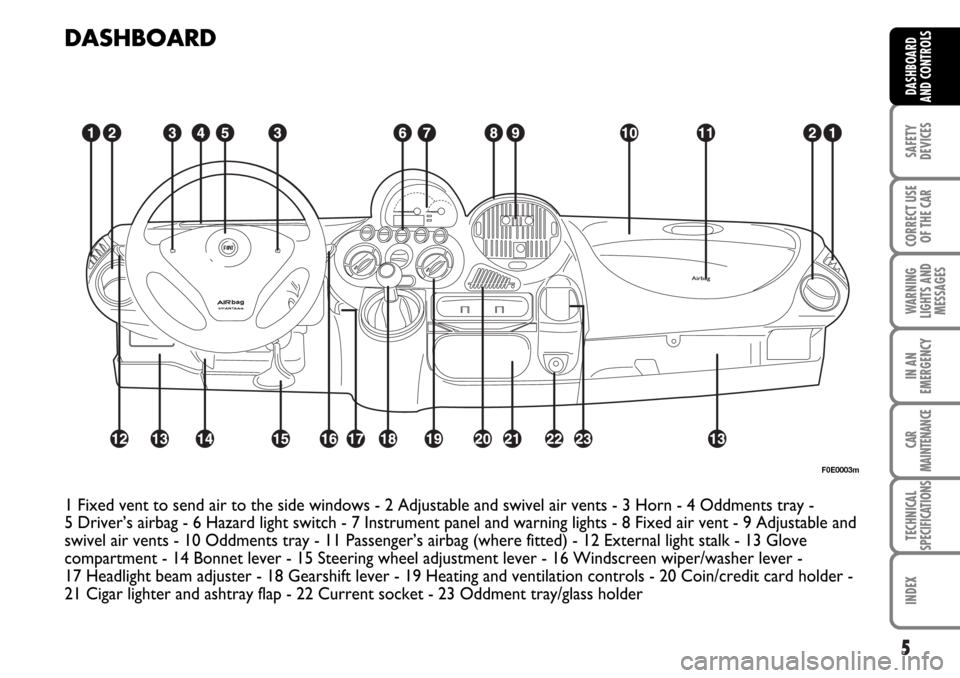
DASHBOARD
1 Fixed vent to send air to the side windows - 2 Adjustable and swivel air vents - 3 Horn - 4 Oddments tray -
5 Driver’s airbag - 6 Hazard light switch - 7 Instrument panel and warning lights - 8 Fixed air vent - 9 Adjustable and
swivel air vents - 10 Oddments tray - 11 Passenger’s airbag (where fitted) - 12 External light stalk - 13 Glove
compartment - 14 Bonnet lever - 15 Steering wheel adjustment lever - 16 Windscreen wiper/washer lever -
17 Headlight beam adjuster - 18 Gearshift lever - 19 Heating and ventilation controls - 20 Coin/credit card holder -
21 Cigar lighter and ashtray flap - 22 Current socket - 23 Oddment tray/glass holder
F0E0003m
Page 7 of 266
6
SAFETY
DEVICES
CORRECT USE
OF THE CAR
WARNING
LIGHTS AND
MESSAGES
IN AN
EMERGENCY
CAR
MAINTENANCE
TECHNICAL
SPECIFICATIONS
INDEX
DASHBOARD
AND CONTROLS
SYMBOLS
Special coloured labels have been attached near or actually on some of
the components of your Fiat Multipla. These labels bear symbols that
remind you of the precautions to be taken as regards that particular
component.
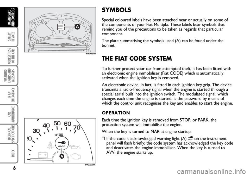
The plate summarising the symbols used (A) can be found under the
bonnet.
THE FIAT CODE SYSTEM
To further protect your car from attempted theft, it has been fitted with
an electronic engine immobiliser (Fiat CODE) which is automatically
activated when the ignition key is removed.
An electronic device, in fact, is fitted in each ignition key grip. The device
transmits a radio-frequency signal when the engine is started through a
special aerial built into the ignition switch. The modulated signal, which
changes each time the engine is started, is the password by means of
which the control unit recognises the key and enables to start the engine.
OPERATION
Each time the ignition key is removed from STOP, or PARK, the
protection system will immobilise the engine.
When the key is turned to MAR at engine startup:
❒If the code is acknowledged warning light (A)
¢on the instrument
panel will flash briefly; the code system has acknowledged the key code
and deactivates the engine immobiliser. When the key is turned to
AVV, the engine starts up.
F0E0657m
F0E0379m
Page 12 of 266
11
SAFETY
DEVICES
CORRECT USE
OF THE CAR
WARNING
LIGHTS AND
MESSAGES
IN AN
EMERGENCY
CAR
MAINTENANCE
TECHNICAL
SPECIFICATIONS
INDEX
DASHBOARD
AND CONTROLS
ELECTRONIC ALARM
The electronic alarm has the following functions:
❒central door locking/unlocking remote control;
❒perimetral surveillance, which picks up opened doors, bonnet and
tailgate;
❒volumetric surveillance, which picks up the movement of any intruders
inside the passenger compartment.
OPERATION
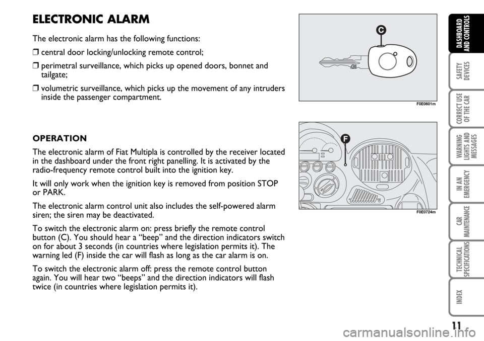
The electronic alarm of Fiat Multipla is controlled by the receiver located
in the dashboard under the front right panelling. It is activated by the
radio-frequency remote control built into the ignition key.
It will only work when the ignition key is removed from position STOP
or PARK.
The electronic alarm control unit also includes the self-powered alarm
siren; the siren may be deactivated.
To switch the electronic alarm on: press briefly the remote control
button (C). You should hear a “beep” and the direction indicators switch
on for about 3 seconds (in countries where legislation permits it). The
warning led (F) inside the car will flash as long as the car alarm is on.
To switch the electronic alarm off: press the remote control button
again. You will hear two “beeps” and the direction indicators will flash
twice (in countries where legislation permits it).
F0E0601m
F0E0724m
Page 13 of 266

12
SAFETY
DEVICES
CORRECT USE
OF THE CAR
WARNING
LIGHTS AND
MESSAGES
IN AN
EMERGENCY
CAR
MAINTENANCE
TECHNICAL
SPECIFICATIONS
INDEX
DASHBOARD
AND CONTROLS
To deactivate the volumetric surveillance: the
volumetric protection function can be deactivated
before activating the electronic alarm in this way: turn
the ignition key from STOP and bring it in rapid
succession onto MAR then back to STOP, after which,
remove the key.
The led (F) on the instrument panel will light up for
about 2 seconds to confirm that the sensors have been
cut off.
To reactivate the volumetric protection (before
enabling the electronic alarm) turn the key to MAR for
more than 30 seconds.
If, however, the volumetric protection has been
deactivated and you wish to operate one of the
electronic controls managed by the ignition key in
MAR (e.g. electric windows) turn the key to MAR, use
the required electric control then bring the key back
to STOP within 30 seconds. In this way the volumetric
protection will not be reactivated.
To cut out the siren: press the remote control button
for about 4 seconds when enabling the electronic
alarm.
Five beeps will be heard which indicate that the siren
has been disabled and the alarm has been enabled.SELF-TEST
If when switching the car alarm on, you hear a “beep”
followed after about one second by a shorter “beep”,
check that the doors, bonnet and boot are all closed
properly, then try switching the alarm on again. If the
problem repeats, contact Fiat Dealership.
PROGRAMMING THE SYSTEM
When your new car is handed over to you, the
electronic alarm has already been programmed by the
Fiat Dealership. Any subsequent programming should
also be carried out by a Fiat Dealership.
IMPORTANT The electronic alarm operation is
prepared according to the laws of the specific country.
This operation is only to be carried out by a Fiat
Dealership, to avoid damaging the electronic memory
storage system.
Page 14 of 266

13
SAFETY
DEVICES
CORRECT USE
OF THE CAR
WARNING
LIGHTS AND
MESSAGES
IN AN
EMERGENCY
CAR
MAINTENANCE
TECHNICAL
SPECIFICATIONS
INDEX
DASHBOARD
AND CONTROLS
WHEN THE ALARM IS TRIGGERED
When the system is on, the electronic alarm comes
into action in the following cases:
❒One of the doors, the bonnet or the tailgate are
opened.
❒The battery is disconnected or the electronic alarm
power supply cables are cut.
❒Something moves in the passenger compartment
(volumetric surveillance).
❒The key is turned to MAR.
When the alarm is triggered, the siren sounds for
about 26 seconds (for a maximum of 3 cycles at 6
second intervals if the cause of the alarm persists) and
the direction indicators will flash for about 5 minutes
(only in countries where legislation permits it).
Once the alarm situation has been resolved, the alarm
system continues its surveillance. To cut off the alarm
before this, press the remote control button.
HOW TO DEACTIVATE THE ALARM
To switch the alarm off, press the remote control
button on the key.
In countries where admitted by law regulations, the
system is preset for an emergency procedure to be
carried out when the alarm does not turn off (due to
flat remote control battery or system fault):❒open the door after unlocking the lock with the key,
❒fit the key into the ignition switch,
❒turn the key to MAR.
To reactivate the alarm after the emergency
procedure, turn the key to STOP and remove it. Then,
press twice the remote control button: first press will
re-align the system (this because the last operation for
excluding the alarm was performed using the key and
not the remote control), the second press will
reactivate the alarm.
When using the key, if the remote control battery is
flat the key led will flash once.
Flat battery condition is also indicated by the
dashboard led glowing steadily for 2 minutes each time
the alarm is deactivated.
In this event the key battery should be replaced by a
new one of the equivalent type on sale c/o normal
retailers.
If it is not possible to switch on the alarm with a new
remote control battery, contact Fiat Dealership to
have the system checked.
IMPORTANT If the car is to remain inactive for a
prolonged length of time (over three weeks) and
security conditions permitting, it is advisable to
operate central locking turning the key in the door
lock to avoid engaging the alarm and draining the
battery.
Page 15 of 266
14
SAFETY
DEVICES
CORRECT USE
OF THE CAR
WARNING
LIGHTS AND
MESSAGES
IN AN
EMERGENCY
CAR
MAINTENANCE
TECHNICAL
SPECIFICATIONS
INDEX
DASHBOARD
AND CONTROLS
Since the electronic car alarm absorbs electricity, if you will not be using your car for more than a month,
switch the system off with the remote control.HOW TO KNOW WHETHER THE ALARM HAS GONE OFF
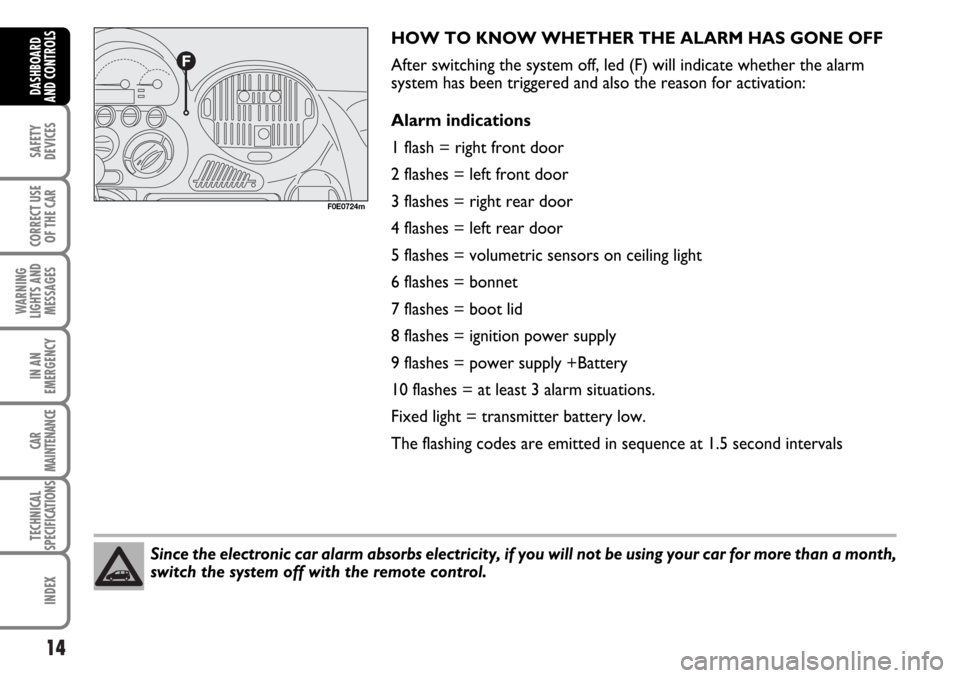
After switching the system off, led (F) will indicate whether the alarm
system has been triggered and also the reason for activation:
Alarm indications
1 flash = right front door
2 flashes = left front door
3 flashes = right rear door
4 flashes = left rear door
5 flashes = volumetric sensors on ceiling light
6 flashes = bonnet
7 flashes = boot lid
8 flashes = ignition power supply
9 flashes = power supply +Battery
10 flashes = at least 3 alarm situations.
Fixed light = transmitter battery low.
The flashing codes are emitted in sequence at 1.5 second intervals
F0E0724m
Page 86 of 266
85
SAFETY
DEVICES
CORRECT USE
OF THE CAR
WARNING
LIGHTS AND
MESSAGES
IN AN
EMERGENCY
CAR
MAINTENANCE
TECHNICAL
SPECIFICATIONS
INDEX
DASHBOARD
AND CONTROLS
BONNET
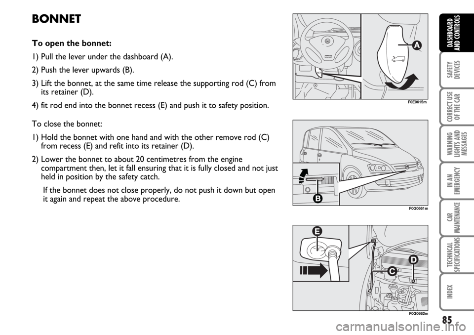
To open the bonnet:
1) Pull the lever under the dashboard (A).
2) Push the lever upwards (B).
3) Lift the bonnet, at the same time release the supporting rod (C) from
its retainer (D).
4) fit rod end into the bonnet recess (E) and push it to safety position.
To close the bonnet:
1) Hold the bonnet with one hand and with the other remove rod (C)
from recess (E) and refit into its retainer (D).
2) Lower the bonnet to about 20 centimetres from the engine
compartment then, let it fall ensuring that it is fully closed and not just
held in position by the safety catch.
If the bonnet does not close properly, do not push it down but open
it again and repeat the above procedure.
F0E0615m
F0G0661m
F0G0662m
Page 87 of 266
86
SAFETY
DEVICES
CORRECT USE
OF THE CAR
WARNING
LIGHTS AND
MESSAGES
IN AN
EMERGENCY
CAR
MAINTENANCE
TECHNICAL
SPECIFICATIONS
INDEX
DASHBOARD
AND CONTROLS
WARNINGThe bonnet might fall violently if the support rod is not positioned properly. This
should only be done when the car is stationary.
WARNINGBefore opening the bonnet make sure the windscreen wiper arm is not lifted from
the windscreen.
If the engine is hot, be very careful when you put your hands under the bonnet as
you risk burning yourself. Remember that while the engine is hot, the electric fan
can start up and cause injury. Wait for the engine to cool.WARNING
Scarves, ties and other loose articles of clothing could easily get caught up in
moving parts. This can be extremely dangerous.WARNING
WARNINGFor safety reasons the bonnet must be closed properly to avoid its opening while
the car is travelling. Therefore, always check it is properly closed and the catch
engaged. Should you notice that the catch is not perfectly engaged when
travelling, stop the car immediately and close the bonnet.
Page 208 of 266
207
SAFETY
DEVICES
CORRECT USE
OF THE CAR
WARNING
LIGHTS AND
MESSAGES
TECHNICAL
SPECIFICATIONS
INDEX
DASHBOARD
AND CONTROLS
IN AN
EMERGENCY
CAR
MAINTENANCE
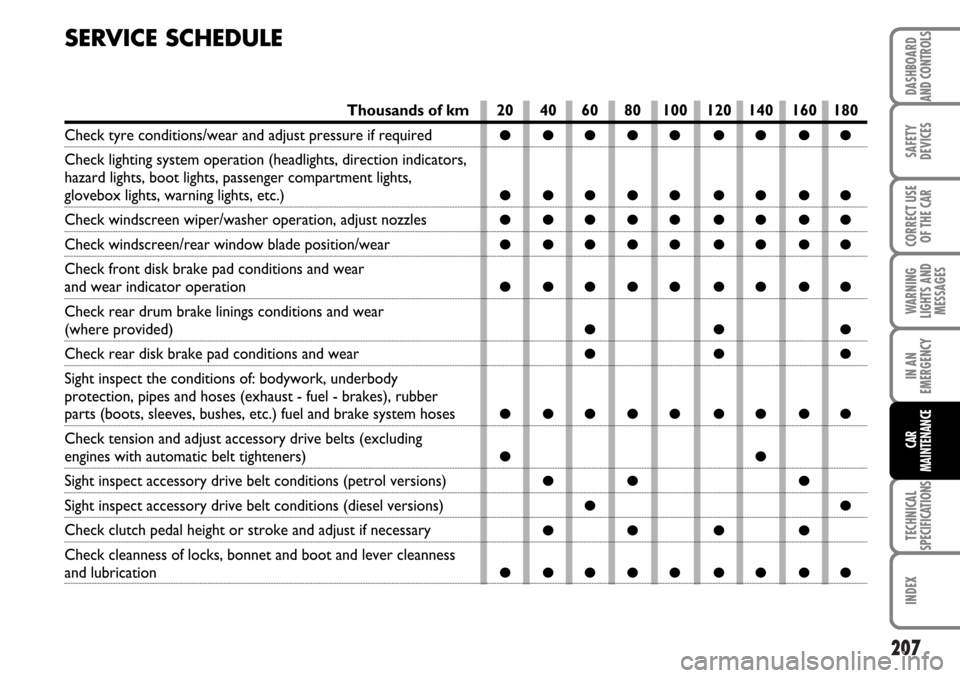
SERVICE SCHEDULE
20 40 60 80 100 120 140 160 180
●●●●● ●●●●
●●●●● ●●●●
●●●●● ●●●●
●●●●● ●●●●
●●●●● ●●●●
●●●
●●●
●●●●● ●●●●
●●
●● ●
●●
●● ● ●
●●●●● ●●●●
Thousands of km
Check tyre conditions/wear and adjust pressure if required
Check lighting system operation (headlights, direction indicators,
hazard lights, boot lights, passenger compartment lights,
glovebox lights, warning lights, etc.)
Check windscreen wiper/washer operation, adjust nozzles
Check windscreen/rear window blade position/wear
Check front disk brake pad conditions and wear
and wear indicator operation
Check rear drum brake linings conditions and wear
(where provided)
Check rear disk brake pad conditions and wear
Sight inspect the conditions of: bodywork, underbody
protection, pipes and hoses (exhaust - fuel - brakes), rubber
parts (boots, sleeves, bushes, etc.) fuel and brake system hoses
Check tension and adjust accessory drive belts (excluding
engines with automatic belt tighteners)
Sight inspect accessory drive belt conditions (petrol versions)
Sight inspect accessory drive belt conditions (diesel versions)
Check clutch pedal height or stroke and adjust if necessary
Check cleanness of locks, bonnet and boot and lever cleanness
and lubrication