sensor FIAT MULTIPLA 2006 1.G Owners Manual
[x] Cancel search | Manufacturer: FIAT, Model Year: 2006, Model line: MULTIPLA, Model: FIAT MULTIPLA 2006 1.GPages: 266, PDF Size: 4.61 MB
Page 5 of 266
4
SAFETY
DEVICES
CORRECT USE
OF THE CAR
WARNING
LIGHTS AND
MESSAGES
IN AN
EMERGENCY
CAR
MAINTENANCE
TECHNICAL
SPECIFICATIONS
INDEX
DASHBOARD
AND CONTROLSDASHBOARD ...................................................................... 5
SYMBOLS ............................................................................... 6
THE FIAT CODE SYSTEM ................................................ 6
THE KEYS .............................................................................. 8
ELECTRONIC ALARM ....................................................... 11
IGNITION SWITCH ........................................................... 15
INSTRUMENT PANEL ....................................................... 17
INSTRUMENTS .................................................................... 18
RICONFIGURABLE MULTIFUNCTION DISPLAY ..... 22
SEATS ..................................................................................... 41
HEAD RESTRAINTS ........................................................... 44
STEERING WHEEL ............................................................. 45
REARVIEW MIRRORS ........................................................ 46
HEATING/AND CLIMATE CONTROL SYSTEM ....... 48
HEATING AND VENTILATION ..................................... 50
MANUAL CLIMATE CONTROL SYSTEM ................... 52
AUTOMATIC CLIMATE CONTROL SYSTEM ............. 54
EXTERNAL LIGHTS ........................................................... 59
WINDOW CLEANING ..................................................... 61
CEILING LIGHT ................................................................... 63
CONTROLS .......................................................................... 65INTERIOR EQUIPMENT ................................................... 67
ELECTRICALLY CONTROLLED
DOUBLE SUNROOF ........................................................... 72
DOORS .................................................................................. 74
ELECTRIC WINDOWS ..................................................... 76
BOOT ..................................................................................... 78
BONNET ............................................................................... 85
ROOF RACK/SKI RACK ................................................... 87
HEADLIGHTS ....................................................................... 88
ABS SYSTEM .......................................................................... 90
ESP SYSTEM .......................................................................... 92
EOBD SYSTEM ..................................................................... 96
PARKING SENSORS ........................................................... 97
MULTIPLA VAN ................................................................... 99
SOUND SYSTEM ................................................................. 102
AT THE FILLING STATION ............................................. 107
PROTECTING THE ENVIRONMENT ........................... 109
D D
A A
S S
H H
B B
O O
A A
R R
D D
A A
N N
D D
C C
O O
N N
T T
R R
O O
L L
S S
Page 13 of 266

12
SAFETY
DEVICES
CORRECT USE
OF THE CAR
WARNING
LIGHTS AND
MESSAGES
IN AN
EMERGENCY
CAR
MAINTENANCE
TECHNICAL
SPECIFICATIONS
INDEX
DASHBOARD
AND CONTROLS
To deactivate the volumetric surveillance: the
volumetric protection function can be deactivated
before activating the electronic alarm in this way: turn
the ignition key from STOP and bring it in rapid
succession onto MAR then back to STOP, after which,
remove the key.
The led (F) on the instrument panel will light up for
about 2 seconds to confirm that the sensors have been
cut off.
To reactivate the volumetric protection (before
enabling the electronic alarm) turn the key to MAR for
more than 30 seconds.
If, however, the volumetric protection has been
deactivated and you wish to operate one of the
electronic controls managed by the ignition key in
MAR (e.g. electric windows) turn the key to MAR, use
the required electric control then bring the key back
to STOP within 30 seconds. In this way the volumetric
protection will not be reactivated.
To cut out the siren: press the remote control button
for about 4 seconds when enabling the electronic
alarm.
Five beeps will be heard which indicate that the siren
has been disabled and the alarm has been enabled.SELF-TEST
If when switching the car alarm on, you hear a “beep”
followed after about one second by a shorter “beep”,
check that the doors, bonnet and boot are all closed
properly, then try switching the alarm on again. If the
problem repeats, contact Fiat Dealership.
PROGRAMMING THE SYSTEM
When your new car is handed over to you, the
electronic alarm has already been programmed by the
Fiat Dealership. Any subsequent programming should
also be carried out by a Fiat Dealership.
IMPORTANT The electronic alarm operation is
prepared according to the laws of the specific country.
This operation is only to be carried out by a Fiat
Dealership, to avoid damaging the electronic memory
storage system.
Page 15 of 266
14
SAFETY
DEVICES
CORRECT USE
OF THE CAR
WARNING
LIGHTS AND
MESSAGES
IN AN
EMERGENCY
CAR
MAINTENANCE
TECHNICAL
SPECIFICATIONS
INDEX
DASHBOARD
AND CONTROLS
Since the electronic car alarm absorbs electricity, if you will not be using your car for more than a month,
switch the system off with the remote control.HOW TO KNOW WHETHER THE ALARM HAS GONE OFF
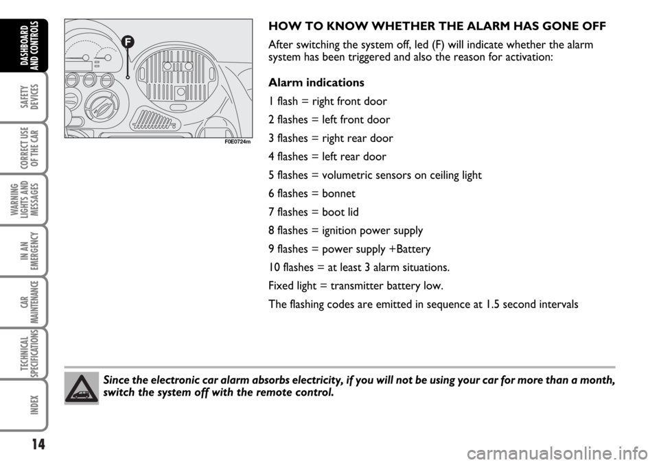
After switching the system off, led (F) will indicate whether the alarm
system has been triggered and also the reason for activation:
Alarm indications
1 flash = right front door
2 flashes = left front door
3 flashes = right rear door
4 flashes = left rear door
5 flashes = volumetric sensors on ceiling light
6 flashes = bonnet
7 flashes = boot lid
8 flashes = ignition power supply
9 flashes = power supply +Battery
10 flashes = at least 3 alarm situations.
Fixed light = transmitter battery low.
The flashing codes are emitted in sequence at 1.5 second intervals
F0E0724m
Page 59 of 266

58
SAFETY
DEVICES
CORRECT USE
OF THE CAR
WARNING
LIGHTS AND
MESSAGES
IN AN
EMERGENCY
CAR
MAINTENANCE
TECHNICAL
SPECIFICATIONS
INDEX
D AND
CONTROLS
If there is a fault
If an anomaly affecting the automatic system is
detected the words “AIR-COND FAULTY” will be
displayed.
The automatic system will continue to work for as
long as possible.If the fault involves the fan control (C) and the fan still
works, it will automatically operate at 1st speed.
If the fault involves an air temperature sensor, the
required air temperature control (A) will work as a
manual air temperature mixing control.
Climate control functions in automatic mode
Reason
To reach the required
temperature as soon as possible
after you get into the car
To reach the new temperature
required as quickly as possible
To prevent the entry of harmful
gas; to prevent the windows
steaming up; to speed up air
cooling
Fast window
demisting/defrosting Automatically enabled
function
Compressor on if the required
temperature is lower than or the
same as that outside
Compressor on if the required
temperature is lower than or the
same as that outside
Compressor on
Compressor on - Maximum air
flow/temperature - Air
recirculation off - Air distribution
to windows Signal to
user
Button √led on
Button √led on
Buttons √
and Tled on
Button √led on
Button Tled off Action performedby the user
Car start-up
(key to MAR)
Required
temperature
variation
Recirculation Ton
MAX/DEF
function on
Page 98 of 266
97
SAFETY
DEVICES
CORRECT USE
OF THE CAR
WARNING
LIGHTS AND
MESSAGES
IN AN
EMERGENCY
CAR
MAINTENANCE
TECHNICAL
SPECIFICATIONS
INDEX
DASHBOARD
AND CONTROLS
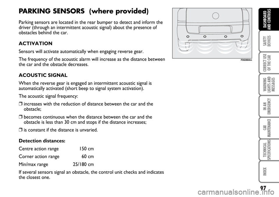
F0G0664m
PARKING SENSORS (where provided)
Parking sensors are located in the rear bumper to detect and inform the
driver (through an intermittent acoustic signal) about the presence of
obstacles behind the car.
ACTIVATION
Sensors will activate automatically when engaging reverse gear.
The frequency of the acoustic alarm will increase as the distance between
the car and the obstacle decreases.
ACOUSTIC SIGNAL
When the reverse gear is engaged an intermittent acoustic signal is
automatically activated (short beep to signal system activation).
The acoustic signal frequency:
❒increases with the reduction of distance between the car and the
obstacle;
❒becomes continuous when the distance between the car and the
obstacle is less than 30 cm and stops if the distance increases;
❒is constant if the distance is unvaried.
Detection distances:
Centre action range 150 cm
Corner action range 60 cm
Min/max range 25/180 cm
If several sensors signal an obstacle, the control unit checks and indicates
the closest one.
Page 99 of 266
98
SAFETY
DEVICES
CORRECT USE
OF THE CAR
WARNING
LIGHTS AND
MESSAGES
IN AN
EMERGENCY
CAR
MAINTENANCE
TECHNICAL
SPECIFICATIONS
INDEX
DASHBOARD
AND CONTROLS
FAILURE WARNINGS
In case of parking sensor failure, the driver is warned
by a 3-seconds acoustic signal.
OPERATION WITH TRAILER
Parking sensor operation is deactivated automatically
when the trailer electric cable plug is fitted into the car
tow hook socket.
Sensors are reactivated automatically when removing
the trailer cable plug.GENERAL WARNINGS
❒When parking, take the utmost care to obstacles set
above or under the sensors.
❒Objects set close to the car front or rear part,
under certain circumstances are not detected and
could therefore cause damages to the car or be
damaged.
❒Indications sent by the sensors can be altered by
dirt, snow or ice deposited on the sensors or by
ultrasound systems (e.g.: truck pneumatic brakes or
pneumatic hammers) set nearby the car.
For proper operation, the parking sensors shall be clean from mud, dirt, snow or ice. When cleaning
the sensors, take the utmost care to prevent their damaging; do not use therefore dry or rough
clothes. Sensors shall be washed with clean water and car detergent, if required. In washing
stations, clean sensors quickly keeping the vapour jet/high pressure washing nozzles at 10 cm at
least from the sensors.
WARNINGParking manoeuvres however are always under the driver’s responsibility which
shall always check the absence of people (specially children) or animals in the
manoeuvre space. This system is just a help for the driver but she/he shall never
reduce attention during dangerous manoeuvres even if performed at low speed.
Page 110 of 266
109
SAFETY
DEVICES
CORRECT USE
OF THE CAR
WARNING
LIGHTS AND
MESSAGES
IN AN
EMERGENCY
CAR
MAINTENANCE
TECHNICAL
SPECIFICATIONS
INDEX
DASHBOARD
AND CONTROLS
PROTECTING
THE ENVIRONMENT
Protecting the environment has been the guiding
principle in the design of the Fiat Multipla right from
start. The result is the use of materials and creation of
devices that can reduce or considerably curtail harmful
influences on the environment.The devices for curtailing petrol engine emissions are
the following:
❒three-way catalytic converter;
❒Lambda sensor;
❒fuel evaporation system.
The devices for curtailing diesel fuel engine emissions
are the following:
❒oxidising catalytic converter;
❒exhaust gas recirculation system (E.G.R.).
As a consequence Fiat Multipla is ready to travel with
several advantage points over the most severe
international anti-pollution regulations.
During normal service the catalytic converter reaches high temperatures.
Therefore, do not park the car over inflammable material (grass, dry leaves, pine
needles, etc.): fire danger.WARNING
Page 118 of 266
117
CORRECT USE
OF THE CAR
WARNING
LIGHTS AND
MESSAGES
IN AN
EMERGENCY
CAR
MAINTENANCE
TECHNICAL
SPECIFICATIONS
INDEX
DASHBOARD
AND CONTROLS
SAFETY
DEVICES
PRETENSIONERS
To increase the efficiency of the front seat belts, Fiat Multipla is fitted
with pretensioners on all the three front seats.
Do not place objects under the centre seat as this could damage the
pretensioner system. These devices “feel” through a sensor, that a
violent crash is in progress and rewind the seat belts a few centimetres.
In this way they ensure that the seat belt adheres perfectly to the wearer
before the restraining action begins. The seat belt locks to indicate that
the device has intervened; the seat belt cannot be drawn back up even
when guiding it manually.
WARNINGThe pretensioner can only be used once. After a collision that has triggered it, have
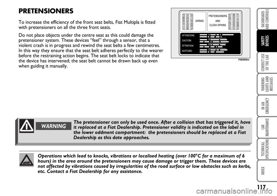
it replaced at a Fiat Dealership. Pretensioner validity is indicated on the label in
the lower oddment compartment: the pretensioners should be replaced at a Fiat
Dealership as this date approaches.
Operations which lead to knocks, vibrations or localised heating (over 100°C for a maximum of 6
hours) in the area around the pretensioners may cause damage or trigger them. These devices are
not affected by vibrations caused by irregularities of the road surface or low obstacles such as kerbs,
etc. Contact a Fiat Dealership for any assistance.
F0E0656m
Page 147 of 266

146
WARNING
LIGHTS AND
MESSAGES
IN AN
EMERGENCY
CAR
MAINTENANCE
TECHNICAL
SPECIFICATIONS
INDEX
DASHBOARD
AND CONTROLS
SAFETY
DEVICES
CORRECT USE
OF THE CAR
INSTALLING THE TOW HOOK
The towing device should be fastened to the body by
specialised personnel according to any additional
and/or integrative information supplied by the
Manufacturer of the device.
Have installation carried out at Fiat Dealership.
The towing device must meet current regulations with
reference to 94/20/EC Directive and subsequent
amendments.
For any version the towing device used must match
the towable weight of the car on which it is to be
installed.
For the electric connection a unified connector should
be used which is generally placed on a special bracket
normally fastened to the towing device, and a special
ECU for external trailer light control shall be installed
on the car.
When fitting the trailer, parking sensors are
deactivated.For the electrical connection, a 7 pin 12VDC
connection is to be used (CUNA/UNI and ISO/DIN
Standards). Follow the instructions provided by the car
manufacturer and/or the tow hitch manufacturer.
An electric brake should be supplied directly by the
battery through a cable with a cross section of no less
than 2.5 mm
2.
IMPORTANT Electric brake or other device shall be
used with running engine.
In addition to the electrical branches, the car’s electric
system can only be connected to the supply cable for
an electric brake and to the cable for an internal light,
though not above 15W.
For connections, use the preset control unit with
battery cable no less than 2.5 mm
2.
The two hitches are shown on the following pages.
Page 157 of 266
156
IN AN
EMERGENCY
CAR
MAINTENANCE
TECHNICAL
SPECIFICATIONS
INDEX
DASHBOARD
AND CONTROLS
SAFETY
DEVICES
CORRECT USE
OF THE CAR
WARNING
LIGHTS AND
MESSAGES
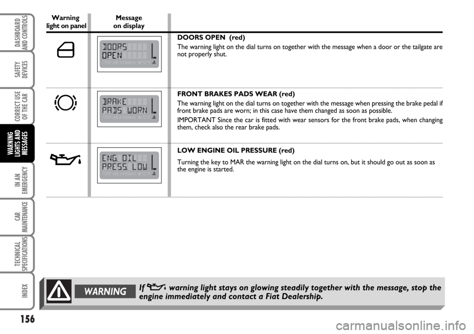
Warning Messagelight on panel on display
DOORS OPEN (red)
The warning light on the dial turns on together with the message when a door or the tailgate are
not properly shut.
FRONT BRAKES PADS WEAR (red)
The warning light on the dial turns on together with the message when pressing the brake pedal if
front brake pads are worn; in this case have them changed as soon as possible.
IMPORTANT Since the car is fitted with wear sensors for the front brake pads, when changing
them, check also the rear brake pads.
LOW ENGINE OIL PRESSURE (red)
Turning the key to MAR the warning light on the dial turns on, but it should go out as soon as
the engine is started.
d
´
v
WARNINGIf vwarning light stays on glowing steadily together with the message, stop the
engine immediately and contact a Fiat Dealership.