FIAT PANDA 2009 169 / 2.G Owners Manual
Manufacturer: FIAT, Model Year: 2009, Model line: PANDA, Model: FIAT PANDA 2009 169 / 2.GPages: 226, PDF Size: 5.29 MB
Page 141 of 226
140KNOW
YOUR VEHICLE
SAFETY
CORRECT USE
OF THE CAR
WARNING LIGHTS
AND MESSAGES
IN
AN EMERGENCYCAR
MAINTENANCE
TECHNICAL
SPECIFICATIONS
INDEX
F0Z0173m
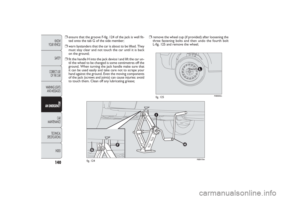
fig. 124
F0Z0233m
fig. 125
❒
remove the wheel cup (if provided) after loosening the
three fastening bolts and then undo the fourth bolt
L-fig. 125 and remove the wheel;
❒
ensure that the groove F-fig. 124 of the jack is well fit-
ted onto the tab G of the side member;
❒
warn bystanders that the car is about to be lifted. They
must stay clear and not touch the car until it is back
on the ground;
❒
fit the handle H into the jack device
Iand lift the car un-
til the wheel to be changed is some centimetres off the
ground. When turning the jack handle make sure that
it can be used easily and take care not to scrape your
hand against the ground. Even the moving components
of the jack (screws and joints) can cause injuries: avoid
to touch them. Clean off any lubricating grease;
135-168 PANDA EN 7-10-2009 14:06 Pagina 140
Page 142 of 226
141KNOW
YOUR VEHICLE
SAFETY
CORRECT USE
OF THE CAR
WARNING LIGHTS
AND MESSAGESIN
AN EMERGENCYCAR
MAINTENANCE
TECHNICAL
SPECIFICATIONS
INDEX
F0Z0204m
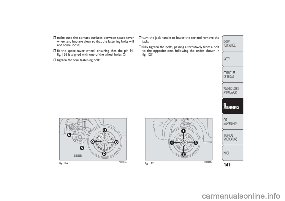
fig. 126
F0Z0206m
fig. 127
❒
turn the jack handle to lower the car and remove the
jack;
❒
fully tighten the bolts, passing alternatively from a bolt
to the opposite one, following the order shown in
fig. 127.
❒
make sure the contact surfaces between space-saver
wheel and hub are clean so that the fastening bolts will
not come loose;
❒
fit the space-saver wheel, ensuring that the pin N-
fig. 126 is aligned with one of the wheel holes O;
❒
tighten the four fastening bolts;
135-168 PANDA EN 7-10-2009 14:06 Pagina 141
Page 143 of 226
142KNOW
YOUR VEHICLE
SAFETY
CORRECT USE
OF THE CAR
WARNING LIGHTS
AND MESSAGES
IN
AN EMERGENCYCAR
MAINTENANCE
TECHNICAL
SPECIFICATIONS
INDEX
F0Z0696m
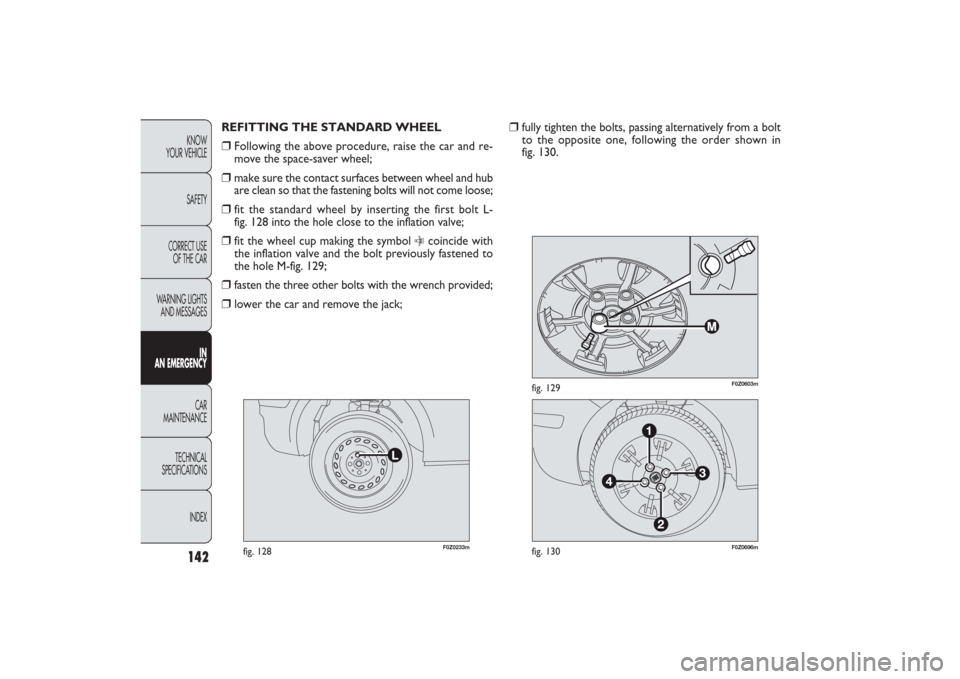
fig. 130
F0Z0603m
fig. 129
❒
fully tighten the bolts, passing alternatively from a bolt
to the opposite one, following the order shown in
fig. 130. REFITTING THE STANDARD WHEEL
❒
Following the above procedure, raise the car and re-
move the space-saver wheel;
❒
make sure the contact surfaces between wheel and hub
are clean so that the fastening bolts will not come loose;
❒
fit the standard wheel by inserting the first bolt L-
fig. 128 into the hole close to the inflation valve;
❒
fit the wheel cup making the symbol
C
coincide with
the inflation valve and the bolt previously fastened to
the hole M-fig. 129;
❒
fasten the three other bolts with the wrench provided;
❒
lower the car and remove the jack;
F0Z0233m
fig. 128
135-168 PANDA EN 7-10-2009 14:06 Pagina 142
Page 144 of 226
143KNOW
YOUR VEHICLE
SAFETY
CORRECT USE
OF THE CAR
WARNING LIGHTS
AND MESSAGESIN
AN EMERGENCYCAR
MAINTENANCE
TECHNICAL
SPECIFICATIONS
INDEX
At the end of the procedure❒
stow the space-saving wheel D-fig. 122 in the space pro-
vided in the boot;
❒
fit the partially-open jack in its box C by forcing it slight-
ly to prevent it from vibrating when travelling;
❒
put the tools back into their locations;
❒
arrange the container and tools in the spare wheel and
secure the clamping device B;
❒
correctly reposition the boot stiff cover.
IMPORTANT Do not use inner tubes with tubeless tyres.
Check the inflation pressure of the tyres and the space-
saving wheel regularly.
IMPORTANT You will need to change the set of bolts if
you want to change the type of wheels fitted (alloy rims
instead of steel rims, and vice versa).The whole set of fas-
tening bolts must be replaced by another set of suitably
sized bolts and use a special space-saving wheel having dif-
ferent building characteristics.
You should keep the bolts and space-saving wheel in case
you decide to use the original type of wheel later on.
F0Z0607m
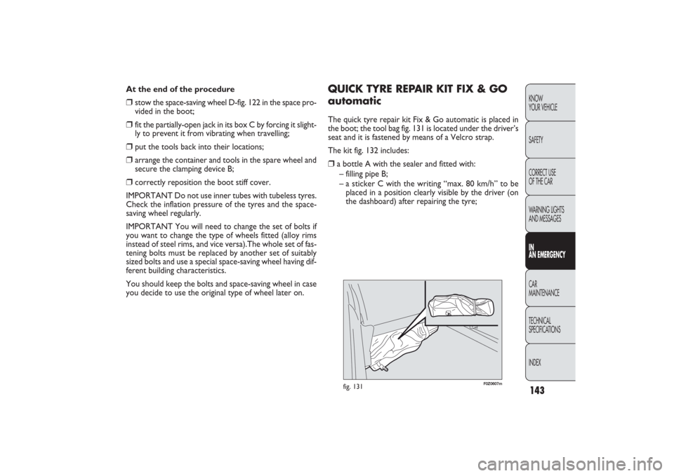
fig. 131
QUICK TYRE REPAIR KIT FIX & GO
automaticThe quick tyre repair kit Fix & Go automatic is placed in
the boot; the tool bag fig. 131 is located under the driver’s
seat and it is fastened by means of a Velcro strap.
The kit fig. 132 includes:❒
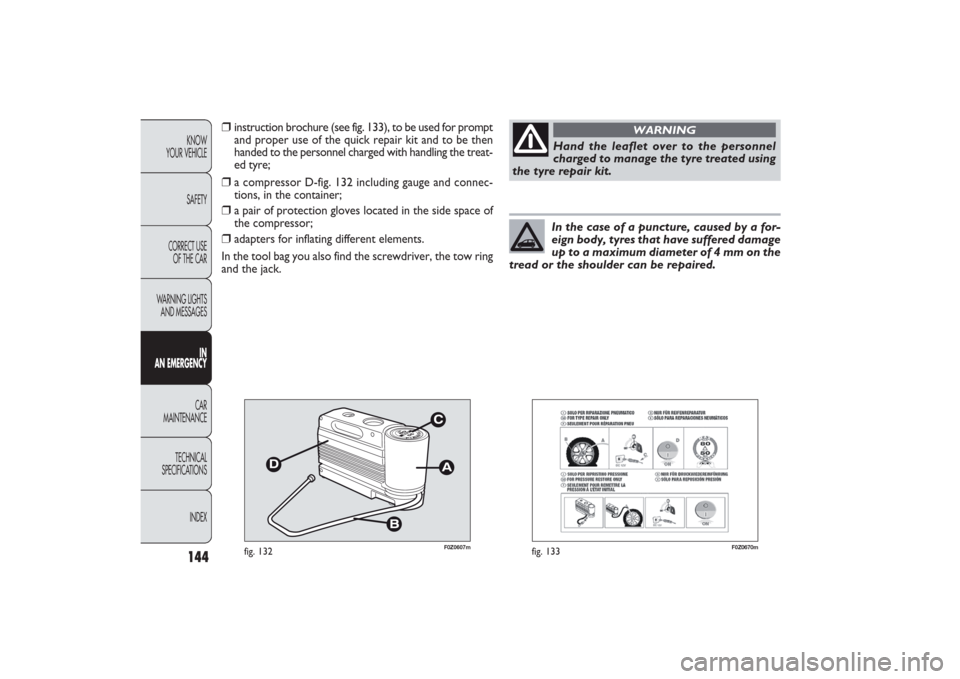
a bottle A with the sealer and fitted with:
– filling pipe B;
– a sticker C with the writing “max. 80 km/h” to be
placed in a position clearly visible by the driver (on
the dashboard) after repairing the tyre;
135-168 PANDA EN 7-10-2009 14:06 Pagina 143
Page 145 of 226
144KNOW
YOUR VEHICLE
SAFETY
CORRECT USE
OF THE CAR
WARNING LIGHTS
AND MESSAGES
IN
AN EMERGENCYCAR
MAINTENANCE
TECHNICAL
SPECIFICATIONS
INDEX
F0Z0670m
fig. 133
Hand the leaflet over to the personnel
charged to manage the tyre treated using
the tyre repair kit.
WARNING
In the case of a puncture, caused by a for-
eign body, tyres that have suffered damage
up to a maximum diameter of 4 mm on the
tread or the shoulder can be repaired.
❒
instruction brochure (see fig. 133), to be used for prompt
and proper use of the quick repair kit and to be then
handed to the personnel charged with handling the treat-
ed tyre;
❒
a compressor D-fig. 132 including gauge and connec-
tions, in the container;
❒
a pair of protection gloves located in the side space of
the compressor;
❒
adapters for inflating different elements.
In the tool bag you also find the screwdriver, the tow ring
and the jack.
F0Z0607m
fig. 132
135-168 PANDA EN 7-10-2009 14:06 Pagina 144
Page 146 of 226
145KNOW
YOUR VEHICLE
SAFETY
CORRECT USE
OF THE CAR
WARNING LIGHTS
AND MESSAGESIN
AN EMERGENCYCAR
MAINTENANCE
TECHNICAL
SPECIFICATIONS
INDEX
Tyre side wall holes and punctures cannot
be repaired. Do not use the quick repair
kit if the tyre is damaged as the vehicle has run on
a flat tyre.
WARNING
If the wheel rim is damaged (bad groove
distortion causing air leakage) it cannot
be repaired. Do not remove the foreign body
(screws or nails) from the tyre.
WARNING
PLEASE REMEMBER THAT:
The sealing fluid of the quick tyre repair kit is effective with
external temperatures between −20 °C and +50 °C.
The sealing fluid has a limited life.
Never not operate the compressor for
longer than 20 consecutive minutes. Risk
of overheating. The quick repair kit is not suitable
for definitive repairs. Tyres may only be repaired
temporarily.
WARNING
The bottle contains ethylene glycol. It con-
tains latex that might cause allergic reac-
tions. It is harmful if swallowed. It is irritant for the
eyes in case of contact. It may cause sensitisation
by inhalation or contact. Avoid contact with your
eyes, skin and clothes. In the event of contact, wash
immediately with plenty of water. Do not induce
vomit if swallowed. Rinse your mouth and drink
plenty of water. Call a doctor immediately. Keep
away from children. The product must not be used
by asthmatics. Do not inhale the vapours during in-
sertion and suction. Call a doctor immediately if al-
lergic reactions are noted. Store the bottle in the
specific compartment, away from sources of heat.
The sealant fluid has a limited life.
WARNING
135-168 PANDA EN 7-10-2009 14:07 Pagina 145
Page 147 of 226
146KNOW
YOUR VEHICLE
SAFETY
CORRECT USE
OF THE CAR
WARNING LIGHTS
AND MESSAGES
IN
AN EMERGENCYCAR
MAINTENANCE
TECHNICAL
SPECIFICATIONS
INDEX
F0Z0697m
fig. 134
F0Z0672m
fig. 135
❒
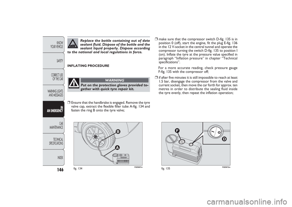
make sure that the compressor switch D-fig. 135 is in
position 0 (off), start the engine, fit the plug E-fig. 136
in the 12 V-socket in the central tunnel and operate the
compressor turning the switch D-fig. 135 to position I
(on). Inflate the tyre at the pressure value specified in
paragraph “Inflation pressure” in chapter “Technical
specifications”.
For a more accurate reading, check pressure gauge
F-fig. 135 with the compressor off;
❒
if after five minutes it is still impossible to reach at least
1.5 bar, disengage the compressor from the valve and
current socket, then move the car forth for approx. ten
metres in order to distribute the sealing fluid inside
the tyre evenly, then repeat the inflation operation;
INFLATING PROCEDURE
Replace the bottle containing out of date
sealant fluid. Dispose of the bottle and the
sealant liquid properly. Dispose according
to the national and local regulations in force.Put on the protection gloves provided to-
gether with quick tyre repair kit.
WARNING
❒
Ensure that the handbrake is engaged. Remove the tyre
valve cap, extract the flexible filler tube A-fig. 134 and
fasten the ring B onto the tyre valve;
135-168 PANDA EN 7-10-2009 14:07 Pagina 146
Page 148 of 226
147KNOW
YOUR VEHICLE
SAFETY
CORRECT USE
OF THE CAR
WARNING LIGHTS
AND MESSAGESIN
AN EMERGENCYCAR
MAINTENANCE
TECHNICAL
SPECIFICATIONS
INDEX
F0Z0673m
fig. 136
F0Z0698m
fig. 137
❒
if after this operation it is still not possible to reach at
least 1.8 bar after five minutes, do not start driving since
the tyre is excessively damaged and the fast tyre re-
pair kit cannot guarantee suitable sealing. Contact
a Fiat Dealership;
❒
if the tyre reaches the pressure specified in “Inflation
pressure” paragraph in the “Technical Specifications”
chapter, start driving immediately;
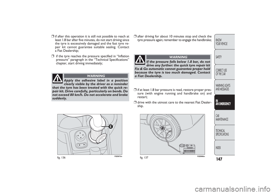
Apply the adhesive label in a position
clearly visible by the driver as a reminder
that the tyre has been treated with the quick re-
pair kit. Drive carefully, particularly on bends. Do
not exceed 80 km/h. Do not accelerate and brake
suddenly.
WARNING
❒
after driving for about 10 minutes stop and check the
tyre pressure again; remember to engage the handbrake;
If the pressure falls below 1.8 bar, do not
drive any further: the quick tyre repair kit
Fix & Go automatic cannot guarantee proper hold
because the tyre is too much damaged. Contact
a Fiat Dealership.
WARNING
❒
if at least 1.8 bar pressure is read, restore proper pres-
sure (with engine running and handbrake on) and
restart;
❒
drive with the utmost care to the nearest Fiat Dealer-
ship.
135-168 PANDA EN 7-10-2009 14:07 Pagina 147
Page 149 of 226
148KNOW
YOUR VEHICLE
SAFETY
CORRECT USE
OF THE CAR
WARNING LIGHTS
AND MESSAGES
IN
AN EMERGENCYCAR
MAINTENANCE
TECHNICAL
SPECIFICATIONS
INDEX
F0Z0699m
fig. 138
F0Z0676m
fig. 139
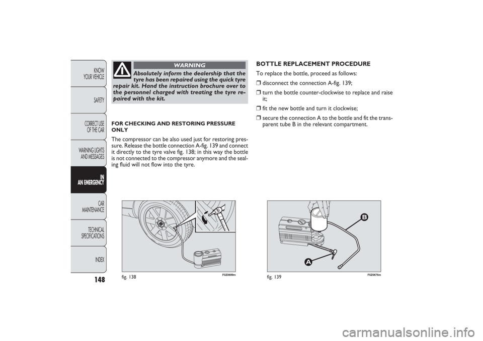
BOTTLE REPLACEMENT PROCEDURE
To replace the bottle, proceed as follows:❒
disconnect the connection A-fig. 139;
❒
turn the bottle counter-clockwise to replace and raise
it;
❒
fit the new bottle and turn it clockwise;
❒
secure the connection A to the bottle and fit the trans-
parent tube B in the relevant compartment.
Absolutely inform the dealership that the
tyre has been repaired using the quick tyre
repair kit. Hand the instruction brochure over to
the personnel charged with treating the tyre re-
paired with the kit.
WARNING
FOR CHECKING AND RESTORING PRESSURE
ONLYThe compressor can be also used just for restoring pres-
sure. Release the bottle connection A-fig. 139 and connect
it directly to the tyre valve fig. 138; in this way the bottle
is not connected to the compressor anymore and the seal-
ing fluid will not flow into the tyre.
135-168 PANDA EN 7-10-2009 14:07 Pagina 148
Page 150 of 226
149KNOW
YOUR VEHICLE
SAFETY
CORRECT USE
OF THE CAR
WARNING LIGHTS
AND MESSAGESIN
AN EMERGENCYCAR
MAINTENANCE
TECHNICAL
SPECIFICATIONS
INDEX
CHANGING A BULBGENERAL INSTRUCTIONS❒
Before changing a bulb check the contacts for oxidation;
❒
burnt bulbs must be replaced by others of the same type
and power;
❒
always check the headlight beam aiming after changing
a bulb;
❒
when a light is not working, check that the corre-
sponding fuse is intact before changing a bulb. For the
location of fuses, refer to the paragraph “Replacing fus-
es” in this chapter.
Modifications or repairs to the electric sys-
tem that are not carried out properly or
do not take the system technical specifications in-
to account can cause malfunctions leading to the
risk of fire.
WARNING
Halogen bulbs contain gas under pressure;
if they break, glass fragments may be dis-
persed.
WARNING
When handling halogen bulbs, only touch
the metal part. If the transparent bulb is
touched with the fingers, its lighting inten-
sity is reduced and life of the bulb may be com-
promised. In the event of accidental contact, wipe
the bulb with a cloth moistened with alcohol
and leave it to dry.
IMPORTANT The headlight inner surface might be slight-
ly misted: this should not be considered irregular rather
a natural phenomenon due to low temperature and the air
humidity level. Misting will disappear as soon as the head-
lights are turned on. The presence of drops inside the
headlights indicates infiltration of water. Contact a Fiat
Dealership.
Where possible, it is advisable to have bulbs
changed at a Fiat Dealership. The correct
operation and aiming of the outer lights are
absolutely important to the safety of the car and
its passengers and the subject of specific laws about
road traffic.
135-168 PANDA EN 7-10-2009 14:07 Pagina 149