replace light FIAT PANDA 2009 169 / 2.G User Guide
[x] Cancel search | Manufacturer: FIAT, Model Year: 2009, Model line: PANDA, Model: FIAT PANDA 2009 169 / 2.GPages: 226, PDF Size: 5.29 MB
Page 122 of 226
121KNOW
YOUR VEHICLE
SAFETYCORRECT USE
OF THE CARWARNING LIGHTS
AND MESSAGES
IN
AN EMERGENCY
CAR
MAINTENANCE
TECHNICAL
SPECIFICATIONS
INDEX
SNOW TYRESUse snow tyres of the same size as the normal tyres pro-
vided with the car.
Fiat Dealership will be happy to provide advice concern-
ing the most suitable type of tyres for the customer’s re-
quirements.
For the type of tyre to be used, inflation pressures and the
specifications of snow tyres, follow the instructions given
in paragraph “Wheels” in section “Technical specifica-
tions”.
The winter features of these tyres are reduced consider-
ably when the tread depth is below 4 mm. Replace them
in this case.
Due to snow tyre features, under normal conditions of
use or on long motorway journeys, the performance of
these tyres is much lower than that of standard tyres. Lim-
it performance according to the use for which they were
certified.
IMPORTANT When snow tyres are used with a max.
speed index below the one that can be reached by the
car (increased by 5%), place a notice in the passenger’s
compartment, plainly in the driver’s view which states the
max. permissible speed of the snow tyres (as per EC
Directive).
The max. speed of snow tyres with “Q”
marking is 160 km/h. The Highway Code
speed limits must however be always complied
with.
WARNING
All four tyres should be the same (brand and track) to
ensure greater safety when driving and braking and bet-
ter driveability.
Remember that it is inappropriate to change the rotation
direction of tyres.
111-122 PANDA EN 7-10-2009 15:01 Pagina 121
Page 138 of 226
137KNOW
YOUR VEHICLE
SAFETY
CORRECT USE
OF THE CAR
WARNING LIGHTS
AND MESSAGESIN
AN EMERGENCYCAR
MAINTENANCE
TECHNICAL
SPECIFICATIONS
INDEX
REPLACING A WHEELGENERAL INSTRUCTIONS
The car can be delivered (upon request/where provided)
with standard spare wheel or space-saver wheel; see
changing instructions on the following paragraphs. Wheel
changing and correct use of the jack and spare wheel call
for some precautions as listed below.
The space-saver wheel (where provided) is
specific to your car, do not use it on other
models, nor use the spare wheel of other models
on your car. The space-saver wheel must only be
used in case of emergency. It shall only be used for
the distance necessary to reach a service point and
the car speed shall not exceed 80 km/h. The spare
wheel has an orange sticker that summarises the
main cautions for use and limitations. The sticker
should never be removed or covered. Never apply
a wheel cup on a space-saver wheel. The sticker
gives the following information in four languages:
Caution! For temporary use only! 80 km/h max.!
Replace by standard wheel as soon as possible. Do
not cover this label in use. If you change the type
of wheel (alloy rims instead of steel rims) you will
have to change the entire set of fastening bolts with
another set of suitably sized bolts.
WARNING
Alert other drivers that the car is station-
ary in compliance with local regulations:
hazard warning lights, warning triangle, etc. Any
passengers on board should leave the car, espe-
cially if it is heavily laden. Passengers should stay
away from on-coming traffic while the wheel is
being changed. If parked on a slope or rough sur-
face, chock the wheels with wedges or other suit-
able devices.
WARNING
The driving features of the car may change
when a space-saver wheel is fitted. Avoid
sudden acceleration and braking, sudden steering
and fast cornering. The total life of a space-saver
wheel is approximately 3000 km, after which it
must be replaced by another wheel of the same
type. Never attempt to fit a conventional tyre on
a rim designed for use as a space-saver wheel.
Have the punctured wheel repaired and replaced
as soon as possible. Two or more space-saver
wheels should never be used together. Do not
grease the threads of bolts before installing them:
they might slip out.
WARNING
135-168 PANDA EN 7-10-2009 14:06 Pagina 137
Page 139 of 226
138KNOW
YOUR VEHICLE
SAFETY
CORRECT USE
OF THE CAR
WARNING LIGHTS
AND MESSAGES
IN
AN EMERGENCYCAR
MAINTENANCE
TECHNICAL
SPECIFICATIONS
INDEX
F0Z0171m
fig. 121
Please note that:❒
the jack weights 1.76 kg;
❒
the jack requires no adjustment;
❒
the jack cannot be repaired. If it breaks it must be re-
placed with a new jack;
❒
no tool other than its cranking device may be fitted on
the jack.
To change a wheel proceed as follows:
❒
stop the car in a position so that it is not a danger for
on-coming traffic and where you can replace the wheel
safely. The ground must be flat and compact;
❒
turn the engine off and pull up the handbrake.
❒
engage the first gear or reverse;
❒
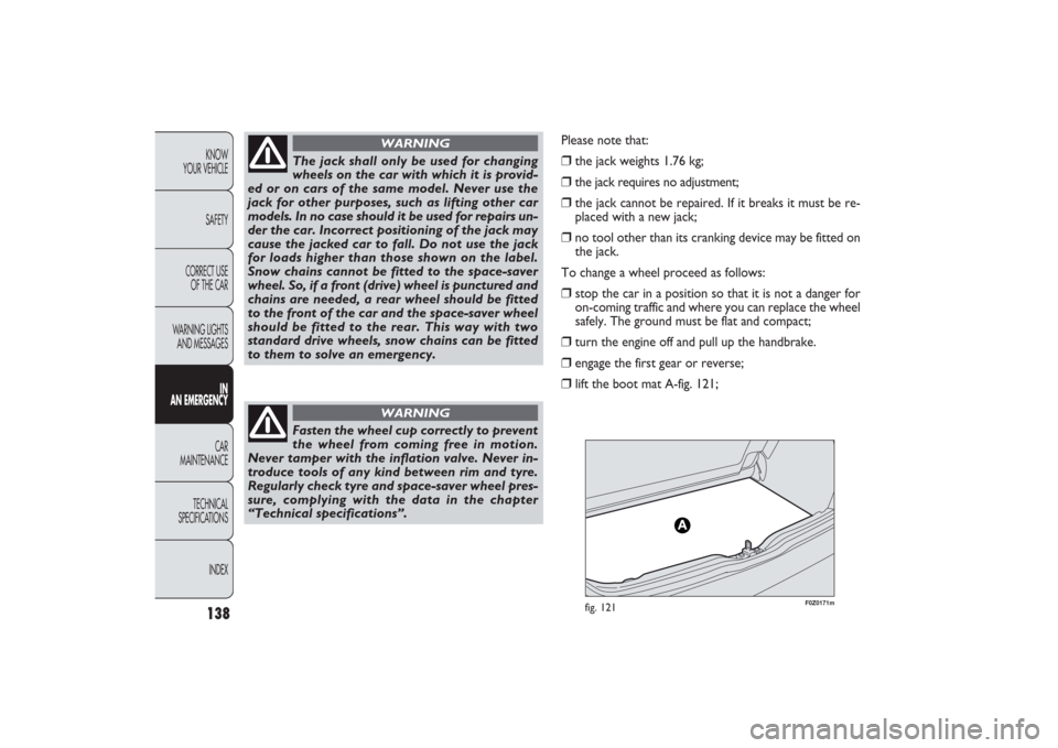
lift the boot mat A-fig. 121;
Fasten the wheel cup correctly to prevent
the wheel from coming free in motion.
Never tamper with the inflation valve. Never in-
troduce tools of any kind between rim and tyre.
Regularly check tyre and space-saver wheel pres-
sure, complying with the data in the chapter
“Technical specifications”.
WARNING
The jack shall only be used for changing
wheels on the car with which it is provid-
ed or on cars of the same model. Never use the
jack for other purposes, such as lifting other car
models. In no case should it be used for repairs un-
der the car. Incorrect positioning of the jack may
cause the jacked car to fall. Do not use the jack
for loads higher than those shown on the label.
Snow chains cannot be fitted to the space-saver
wheel. So, if a front (drive) wheel is punctured and
chains are needed, a rear wheel should be fitted
to the front of the car and the space-saver wheel
should be fitted to the rear. This way with two
standard drive wheels, snow chains can be fitted
to them to solve an emergency.
WARNING
135-168 PANDA EN 7-10-2009 14:06 Pagina 138
Page 140 of 226
139KNOW
YOUR VEHICLE
SAFETY
CORRECT USE
OF THE CAR
WARNING LIGHTS
AND MESSAGESIN
AN EMERGENCYCAR
MAINTENANCE
TECHNICAL
SPECIFICATIONS
INDEX
F0Z0078m
fig. 122
F0Z0695m
fig. 123
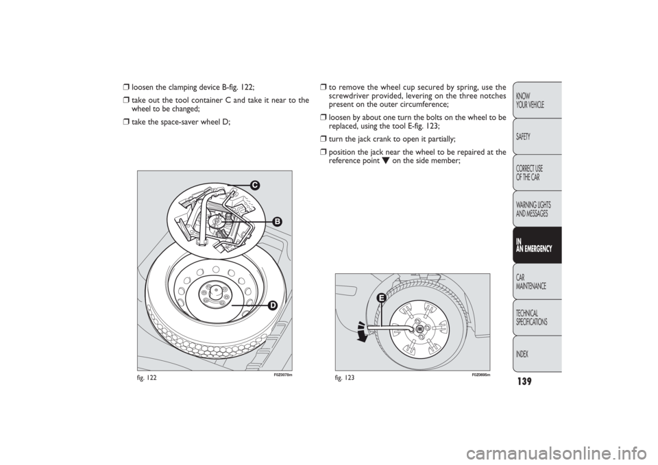
❒
to remove the wheel cup secured by spring, use the
screwdriver provided, levering on the three notches
present on the outer circumference;
❒
loosen by about one turn the bolts on the wheel to be
replaced, using the tool E-fig. 123;
❒
turn the jack crank to open it partially;
❒
position the jack near the wheel to be repaired at the
reference point
O
on the side member;
❒
loosen the clamping device B-fig. 122;
❒
take out the tool container C and take it near to the
wheel to be changed;
❒
take the space-saver wheel D;
135-168 PANDA EN 7-10-2009 14:06 Pagina 139
Page 144 of 226
143KNOW
YOUR VEHICLE
SAFETY
CORRECT USE
OF THE CAR
WARNING LIGHTS
AND MESSAGESIN
AN EMERGENCYCAR
MAINTENANCE
TECHNICAL
SPECIFICATIONS
INDEX
At the end of the procedure❒
stow the space-saving wheel D-fig. 122 in the space pro-
vided in the boot;
❒
fit the partially-open jack in its box C by forcing it slight-
ly to prevent it from vibrating when travelling;
❒
put the tools back into their locations;
❒
arrange the container and tools in the spare wheel and
secure the clamping device B;
❒
correctly reposition the boot stiff cover.
IMPORTANT Do not use inner tubes with tubeless tyres.
Check the inflation pressure of the tyres and the space-
saving wheel regularly.
IMPORTANT You will need to change the set of bolts if
you want to change the type of wheels fitted (alloy rims
instead of steel rims, and vice versa).The whole set of fas-
tening bolts must be replaced by another set of suitably
sized bolts and use a special space-saving wheel having dif-
ferent building characteristics.
You should keep the bolts and space-saving wheel in case
you decide to use the original type of wheel later on.
F0Z0607m
fig. 131
QUICK TYRE REPAIR KIT FIX & GO
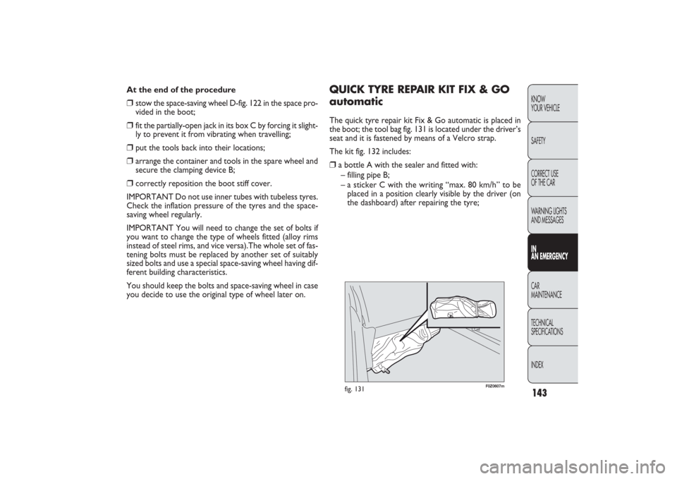
automaticThe quick tyre repair kit Fix & Go automatic is placed in
the boot; the tool bag fig. 131 is located under the driver’s
seat and it is fastened by means of a Velcro strap.
The kit fig. 132 includes:❒
a bottle A with the sealer and fitted with:
– filling pipe B;
– a sticker C with the writing “max. 80 km/h” to be
placed in a position clearly visible by the driver (on
the dashboard) after repairing the tyre;
135-168 PANDA EN 7-10-2009 14:06 Pagina 143
Page 147 of 226
146KNOW
YOUR VEHICLE
SAFETY
CORRECT USE
OF THE CAR
WARNING LIGHTS
AND MESSAGES
IN
AN EMERGENCYCAR
MAINTENANCE
TECHNICAL
SPECIFICATIONS
INDEX
F0Z0697m
fig. 134
F0Z0672m
fig. 135
❒
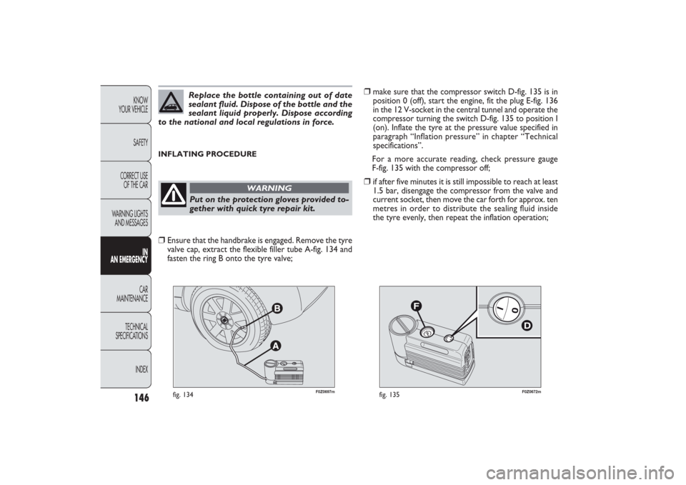
make sure that the compressor switch D-fig. 135 is in
position 0 (off), start the engine, fit the plug E-fig. 136
in the 12 V-socket in the central tunnel and operate the
compressor turning the switch D-fig. 135 to position I
(on). Inflate the tyre at the pressure value specified in
paragraph “Inflation pressure” in chapter “Technical
specifications”.
For a more accurate reading, check pressure gauge
F-fig. 135 with the compressor off;
❒
if after five minutes it is still impossible to reach at least
1.5 bar, disengage the compressor from the valve and
current socket, then move the car forth for approx. ten
metres in order to distribute the sealing fluid inside
the tyre evenly, then repeat the inflation operation;
INFLATING PROCEDURE
Replace the bottle containing out of date
sealant fluid. Dispose of the bottle and the
sealant liquid properly. Dispose according
to the national and local regulations in force.Put on the protection gloves provided to-
gether with quick tyre repair kit.
WARNING
❒
Ensure that the handbrake is engaged. Remove the tyre
valve cap, extract the flexible filler tube A-fig. 134 and
fasten the ring B onto the tyre valve;
135-168 PANDA EN 7-10-2009 14:07 Pagina 146
Page 149 of 226
148KNOW
YOUR VEHICLE
SAFETY
CORRECT USE
OF THE CAR
WARNING LIGHTS
AND MESSAGES
IN
AN EMERGENCYCAR
MAINTENANCE
TECHNICAL
SPECIFICATIONS
INDEX
F0Z0699m
fig. 138
F0Z0676m
fig. 139
BOTTLE REPLACEMENT PROCEDURE
To replace the bottle, proceed as follows:❒
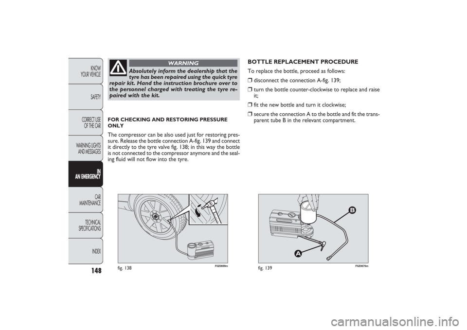
disconnect the connection A-fig. 139;
❒
turn the bottle counter-clockwise to replace and raise
it;
❒
fit the new bottle and turn it clockwise;
❒
secure the connection A to the bottle and fit the trans-
parent tube B in the relevant compartment.
Absolutely inform the dealership that the
tyre has been repaired using the quick tyre
repair kit. Hand the instruction brochure over to
the personnel charged with treating the tyre re-
paired with the kit.
WARNING
FOR CHECKING AND RESTORING PRESSURE
ONLYThe compressor can be also used just for restoring pres-
sure. Release the bottle connection A-fig. 139 and connect
it directly to the tyre valve fig. 138; in this way the bottle
is not connected to the compressor anymore and the seal-
ing fluid will not flow into the tyre.
135-168 PANDA EN 7-10-2009 14:07 Pagina 148
Page 150 of 226
149KNOW
YOUR VEHICLE
SAFETY
CORRECT USE
OF THE CAR
WARNING LIGHTS
AND MESSAGESIN
AN EMERGENCYCAR
MAINTENANCE
TECHNICAL
SPECIFICATIONS
INDEX
CHANGING A BULBGENERAL INSTRUCTIONS❒
Before changing a bulb check the contacts for oxidation;
❒
burnt bulbs must be replaced by others of the same type
and power;
❒
always check the headlight beam aiming after changing
a bulb;
❒
when a light is not working, check that the corre-
sponding fuse is intact before changing a bulb. For the
location of fuses, refer to the paragraph “Replacing fus-
es” in this chapter.
Modifications or repairs to the electric sys-
tem that are not carried out properly or
do not take the system technical specifications in-
to account can cause malfunctions leading to the
risk of fire.
WARNING
Halogen bulbs contain gas under pressure;
if they break, glass fragments may be dis-
persed.
WARNING
When handling halogen bulbs, only touch
the metal part. If the transparent bulb is
touched with the fingers, its lighting inten-
sity is reduced and life of the bulb may be com-
promised. In the event of accidental contact, wipe
the bulb with a cloth moistened with alcohol
and leave it to dry.
IMPORTANT The headlight inner surface might be slight-
ly misted: this should not be considered irregular rather
a natural phenomenon due to low temperature and the air
humidity level. Misting will disappear as soon as the head-
lights are turned on. The presence of drops inside the
headlights indicates infiltration of water. Contact a Fiat
Dealership.
Where possible, it is advisable to have bulbs
changed at a Fiat Dealership. The correct
operation and aiming of the outer lights are
absolutely important to the safety of the car and
its passengers and the subject of specific laws about
road traffic.
135-168 PANDA EN 7-10-2009 14:07 Pagina 149
Page 154 of 226
153KNOW
YOUR VEHICLE
SAFETY
CORRECT USE
OF THE CAR
WARNING LIGHTS
AND MESSAGESIN
AN EMERGENCYCAR
MAINTENANCE
TECHNICAL
SPECIFICATIONS
INDEX
F0Z0092m
fig. 144
F0Z0094m
fig. 146
F0Z0093m
fig. 145
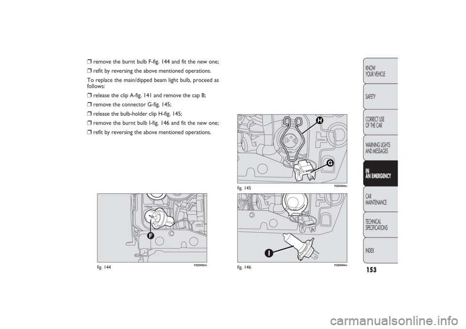
❒
remove the burnt bulb F-fig. 144 and fit the new one;
❒
refit by reversing the above mentioned operations.
To replace the main/dipped beam light bulb, proceed as
follows:
❒
release the clip A-fig. 141 and remove the cap B;
❒
remove the connector G-fig. 145;
❒
release the bulb-holder clip H-fig. 145;
❒
remove the burnt bulb I-fig. 146 and fit the new one;
❒
refit by reversing the above mentioned operations.
135-168 PANDA EN 7-10-2009 14:07 Pagina 153
Page 155 of 226
154KNOW
YOUR VEHICLE
SAFETY
CORRECT USE
OF THE CAR
WARNING LIGHTS
AND MESSAGES
IN
AN EMERGENCYCAR
MAINTENANCE
TECHNICAL
SPECIFICATIONS
INDEX
F0Z0095m
fig. 147
F0Z0227m
fig. 149
F0Z0604m
fig. 148
FRONT FOG LIGHTS
(for versions/markets where provided)
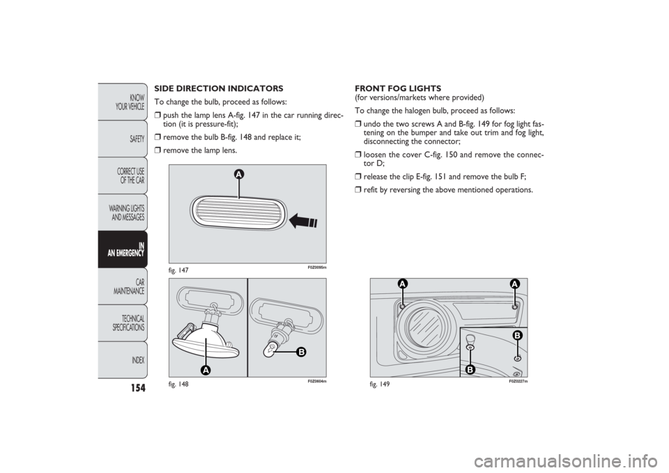
To change the halogen bulb, proceed as follows:❒
undo the two screws A and B-fig. 149 for fog light fas-
tening on the bumper and take out trim and fog light,
disconnecting the connector;
❒
loosen the cover C-fig. 150 and remove the connec-
tor D;
❒
release the clip E-fig. 151 and remove the bulb F;
❒
refit by reversing the above mentioned operations. SIDE DIRECTION INDICATORS
To change the bulb, proceed as follows:
❒
push the lamp lens A-fig. 147 in the car running direc-
tion (it is pressure-fit);
❒
remove the bulb B-fig. 148 and replace it;
❒
remove the lamp lens.
135-168 PANDA EN 7-10-2009 14:07 Pagina 154