Dashboard lights FIAT PANDA 2009 169 / 2.G Owners Manual
[x] Cancel search | Manufacturer: FIAT, Model Year: 2009, Model line: PANDA, Model: FIAT PANDA 2009 169 / 2.GPages: 226, PDF Size: 5.29 MB
Page 4 of 226
3KNOW YOUR
VEHICLESAFETY
CORRECT USE
OF THE CAR
WARNING LIGHTS
AND MESSAGES
IN
AN EMERGENCY
CAR
MAINTENANCE
TECHNICAL
SPECIFICATIONS
INDEX
KNOW YOUR VEHICLE
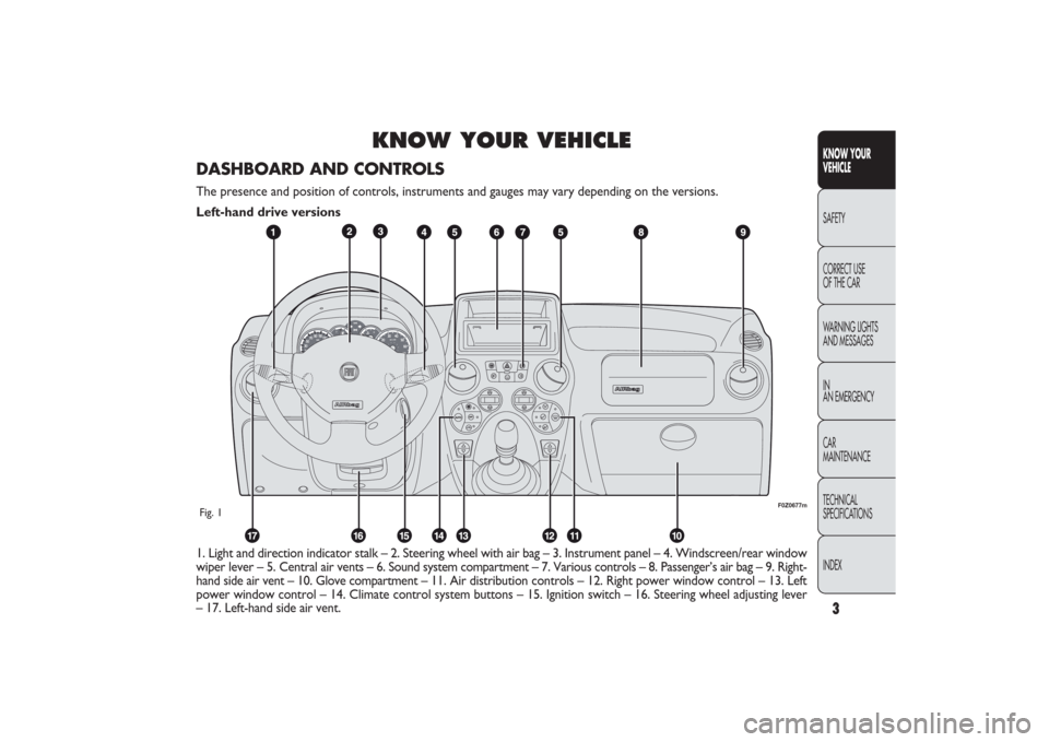
1. Light and direction indicator stalk – 2. Steering wheel with air bag – 3. Instrument panel – 4. Windscreen/rear window
wiper lever – 5. Central air vents – 6. Sound system compartment – 7. Various controls – 8. Passenger’s air bag – 9. Right-
hand side air vent – 10. Glove compartment – 11. Air distribution controls – 12. Right power window control – 13. Left
power window control – 14. Climate control system buttons – 15. Ignition switch – 16. Steering wheel adjusting lever
– 17. Left-hand side air vent.
F0Z0677m
Fig. 1DASHBOARD AND CONTROLSThe presence and position of controls, instruments and gauges may vary depending on the versions.
Left-hand drive versions
001-030 PANDA EN 7-10-2009 13:39 Pagina 3
Page 39 of 226
F0Z0022m
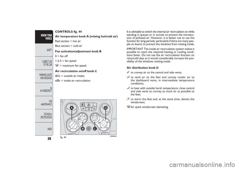
fig. 44
It is advisable to switch the internal air recirculation on while
standing in queues or in tunnels to prevent the introduc-
tion of polluted air. However, it is better not to use the
function for long periods, particularly if there are many peo-
ple on board, to prevent the windows from misting inside.
IMPORTANT The inside air recirculation system makes it
possible to reach the required heating or cooling condi-
tions faster. Do not use the air recirculation function on
rainy/cold days as it would considerably increase the pos-
sibility of the windows misting inside.
Air distribution knob
D
ÂĄ
to convey air to the central and side vents;
ÎĽ
to send air to the feet and convey cooler air to
the dashboard vents, in intermediate temperature
conditions;
w
to heat with outside harsh temperature: close central
and side vents to convey as much air as possible to
the feet;
≤to warm the feet and, at the same time, demist the
windscreen;
-
for quick windscreen demisting. CONTROLS fig. 44
Air temperature knob A (mixing hot/cold air)
Red section = hot air
Blue section = cold air
Fan activation/adjustment knob B
0 = fan off
1-2-3 = fan speed
-
= maximum fan speed
Air recirculation on/off knob
C
U
= outside air intake
T
= inside air recirculation
38
KNOW YOUR
VEHICLE
SAFETY
CORRECT USE
OF THE CAR
WARNING LIGHTS
AND MESSAGES
IN
AN EMERGENCY
CAR
MAINTENANCE
TECHNICAL
SPECIFICATIONS
INDEX
031-064 PANDA EN 7-10-2009 13:43 Pagina 38
Page 47 of 226
ÎĽ
air flow towards the front seat feet area. Due to the
natural tendency of heat to spread upwards, this type
of distribution warms the passenger compartment
up as quickly as possible, providing an immediate
feeling of warmth.
w+ÎĽ
distribution between feet area vents (warmest air)
and dashboard vents (coolest air).
ÂĄ+ÎĽ
distribution between feet area vents and wind-
screen/side front window vents. This type of distri-
bution achieves an adequate warming of the pas-
senger compartment and prevents the windows
from misting up.
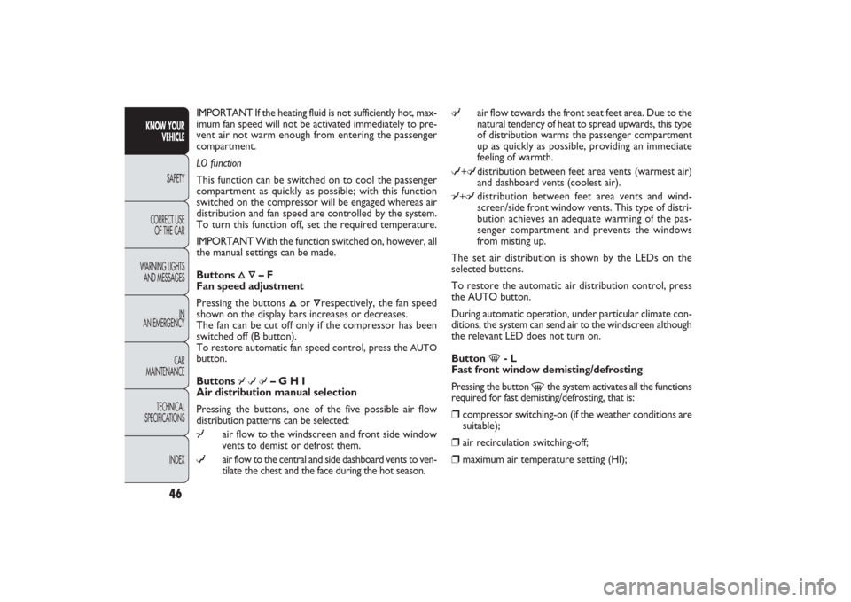
The set air distribution is shown by the LEDs on the
selected buttons.
To restore the automatic air distribution control, press
the AUTO button.
During automatic operation, under particular climate con-
ditions, the system can send air to the windscreen although
the relevant LED does not turn on.
Button
-
- L
Fast front window demisting/defrosting
Pressing the button
-
the system activates all the functions
required for fast demisting/defrosting, that is:
âť’
compressor switching-on (if the weather conditions are
suitable);
âť’
air recirculation switching-off;
âť’
maximum air temperature setting (HI); IMPORTANT If the heating fluid is not sufficiently hot, max-
imum fan speed will not be activated immediately to pre-
vent air not warm enough from entering the passenger
compartment.
LO function
This function can be switched on to cool the passenger
compartment as quickly as possible; with this function
switched on the compressor will be engaged whereas air
distribution and fan speed are controlled by the system.
To turn this function off, set the required temperature.
IMPORTANT With the function switched on, however, all
the manual settings can be made.
Buttons
Ă•Ă”
– F
Fan speed adjustment
Pressing the buttons
Ă•
or
Ôrespectively, the fan speed
shown on the display bars increases or decreases.
The fan can be cut off only if the compressor has been
switched off (B button).
To restore automatic fan speed control, press the
AUTO
button.
Buttons
ÂĄwÎĽ
– G H I
Air distribution manual selection
Pressing the buttons, one of the five possible air flow
distribution patterns can be selected:
ÂĄ
air flow to the windscreen and front side window
vents to demist or defrost them.
w
air flow to the central and side dashboard vents to ven-
tilate the chest and the face during the hot season.
46
KNOW YOUR
VEHICLE
SAFETY
CORRECT USE
OF THE CAR
WARNING LIGHTS
AND MESSAGES
IN
AN EMERGENCY
CAR
MAINTENANCE
TECHNICAL
SPECIFICATIONS
INDEX
031-064 PANDA EN 7-10-2009 13:43 Pagina 46
Page 49 of 226
F0Z0122m
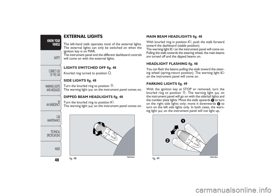
fig. 48
F0Z0126m
fig. 49
MAIN BEAM HEADLIGHTS fig. 48
With knurled ring in position
2
, push the stalk forward
toward the dashboard (stable position).
The warning light
1
on the instrument panel will come on.
Pulling the stalk towards the steering wheel, the main beams
are turned off and the dipped beams on.
HEADLIGHT FLASHING fig. 48
You can flash the beams pulling the stalk toward the steer-
ing wheel (spring-return position). The warning light
1
on the instrument panel will come on.
PARKING LIGHTS fig. 49
With the ignition key at STOP or removed, turn the
knurled ring to position
6
. The warning light
3
on
the instrument panel will go on with the side/tail lights and
the number plate lights. Move the stalk upwards
a
to turn
on the right side lights only; move it downwards b
to
turn on the left side lights only. In both cases, the warn-
ing light
3
on the instrument panel will not light up.
EXTERNAL LIGHTSThe left-hand stalk operates most of the external lights.
The external lights can only be switched on when the
ignition key is on MAR.
The instrument panel and the different dashboard controls
will come on with the external lights.
LIGHTS SWITCHED OFF fig. 48
Knurled ring turned to position O.
SIDE LIGHTS fig. 48
Turn the knurled ring to position
6
.
The warning light
3
on the instrument panel comes on.
DIPPED BEAM HEADLIGHTS fig. 48
Turn the knurled ring to position
2
.
The warning light
3
on the instrument panel comes on.
48
KNOW YOUR
VEHICLE
SAFETY
CORRECT USE
OF THE CAR
WARNING LIGHTS
AND MESSAGES
IN
AN EMERGENCY
CAR
MAINTENANCE
TECHNICAL
SPECIFICATIONS
INDEX
031-064 PANDA EN 7-10-2009 13:43 Pagina 48
Page 52 of 226
51KNOW YOUR
VEHICLESAFETY
CORRECT USE
OF THE CAR
WARNING LIGHTS
AND MESSAGES
IN
AN EMERGENCY
CAR
MAINTENANCE
TECHNICAL
SPECIFICATIONS
INDEX
REAR WINDOW WASHER/WIPER
The device can only work when the ignition key is at MAR.
Turn the knurled ring to
'
to operate the rear window
wiper.
With the windscreen wiper on, turn the knurled ring to
'
to turn on the rear window wiper. In this case the wiper
works (in the different positions) timed with the wind-
screen wiper, but at half speed.
With the windscreen wiper on, engaging reverse gear will
automatically turn the rear window wiper on, in continu-
ous slow operation.
Operation stops by disengaging reverse.
“Smart washing” function
Pushing the stalk towards the dashboard (spring-return
position) will activate the rear window washer.
Keep the stalk pressed, with just one movement, to op-
erate the rear window washer jet and the rear window
wiper itself; the latter automatically turns on if you keep
the stalk pressed for more than half a second.
The rear window wiper stops operating a few strokes af-
ter releasing the stalk; a further “cleaning stroke”, after
a few seconds, completes the wiping operation.
Do not use the rear window wiper to re-
move layers of snow or ice from the wind-
screen. In these conditions, the rear window
wipers may be submitted to excessive effort result-
ing in motor protection cutting in and wiper oper-
ation inhibition for a few seconds. If the operation
is not restored, contact a Fiat Dealership.
031-064 PANDA EN 7-10-2009 13:43 Pagina 51
Page 57 of 226
F0Z0069m
fig. 56
F0Z0035m
fig. 57
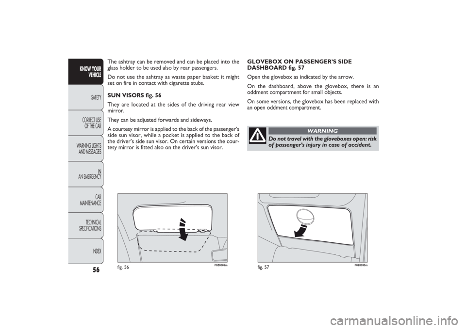
GLOVEBOX ON PASSENGER’S SIDE
DASHBOARD fig. 57
Open the glovebox as indicated by the arrow.
On the dashboard, above the glovebox, there is an
oddment compartment for small objects.
On some versions, the glovebox has been replaced with
an open oddment compartment. The ashtray can be removed and can be placed into the
glass holder to be used also by rear passengers.
Do not use the ashtray as waste paper basket: it might
set on fire in contact with cigarette stubs.
SUN VISORS fig. 56
They are located at the sides of the driving rear view
mirror.
They can be adjusted forwards and sideways.
A courtesy mirror is applied to the back of the passenger’s
side sun visor, while a pocket is applied to the back of
the driver’s side sun visor. On certain versions the cour-
tesy mirror is fitted also on the driver’s sun visor.
56
KNOW YOUR
VEHICLE
SAFETY
CORRECT USE
OF THE CAR
WARNING LIGHTS
AND MESSAGES
IN
AN EMERGENCY
CAR
MAINTENANCE
TECHNICAL
SPECIFICATIONS
INDEX
Do not travel with the gloveboxes open: risk
of passenger’s injury in case of accident.
WARNING
031-064 PANDA EN 7-10-2009 13:43 Pagina 56
Page 70 of 226
The bonnet may drop suddenly if the sup-
porting rod is not positioned properly. This
should only be done when the car is stationary.
WARNING
Before opening the bonnet, check that
windscreen wiper arm is not lifted from
the windscreen.
WARNING
With hot engine, proceed with the utmost
care inside the engine compartment to
avoid burns. Do not place your hands close to the
fan: it might start working also with the ignition
key removed. Wait for engine cooling.
WARNING
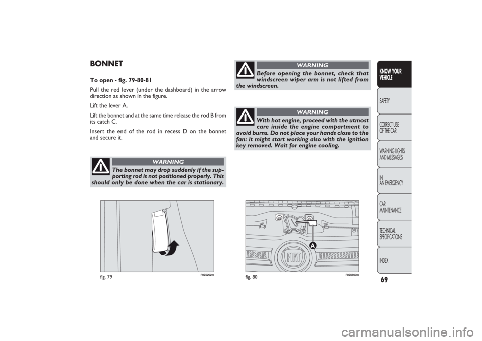
BONNETTo open - fig. 79-80-81
Pull the red lever (under the dashboard) in the arrow
direction as shown in the figure.
Lift the lever A.
Lift the bonnet and at the same time release the rod B from
its catch C.
Insert the end of the rod in recess D on the bonnet
and secure it.
fig. 80
F0Z0690m
fig. 79
F0Z0202m
69KNOW YOUR
VEHICLESAFETY
CORRECT USE
OF THE CAR
WARNING LIGHTS
AND MESSAGES
IN
AN EMERGENCY
CAR
MAINTENANCE
TECHNICAL
SPECIFICATIONS
INDEX
065-090 PANDA EN 7-10-2009 13:45 Pagina 69
Page 99 of 226
98
KNOW YOUR
VEHICLE
SAFETY
CORRECT USE
OF THE CAR
WARNING LIGHTS
AND MESSAGES
IN AN EMERGENCY
CAR
MAINTENANCE
TECHNICAL
SPECIFICATIONS
INDEX
CARRYING CHILDREN SAFELYFor optimal protection in the event of a collision, all pas-
sengers must be seated and wearing adequate restraint
systems.
This is even more important for children.
This prescription is compulsory in all EC countries ac-
cording to EC Directive 2003/20/EC.
Compared with adults, a child’s head is proportionally larg-
er and heavier than the rest of the body, while muscles and
bone structure are not fully developed.
Therefore, correct restraint systems are necessary other
than adult seat belts.
The results of research on the best child restraint system
are contained in the European Standard ECE-R44, which
enforces the use of restraint systems classified into five
groups:
Group 0 0 – 10 kg in weight
Group 0+ 0 – 13 kg in weight
Group 1 9 – 18 kg in weight
Group 2 15 – 25 kg in weight
Group 3 22 – 36 kg in weight
SERIOUS DANGER: never place cradle
child’s seats facing backwards on the front
passenger’s seat of cars fitted with pas-
senger’s air bag. Deployment of the airbag
in an accident could cause fatal injuries
to the baby. It is advisable to carry children always
on the rear seat which is the most protected po-
sition in the event of an accident. Never fit child
seats systems on the front seat if the car is pro-
vided with passenger’s air bag: as the airbag could
cause even fatal injury independently from the
severity of the collision which caused its deploy-
ment. If necessary, children can stay on the front
seat, only if the passenger’s airbag can be disabled.
It is absolutely necessary to check the warning
light
F
on the dashboard to make sure that the
deactivation has actually taken place (see “Pas-
senger’s front air bag”, paragraph “Front air
bags”). Move the passenger’s seat as far back as
possible to avoid contact between the child seat
and the dashboard.
WARNING
All child restraint devices must bear the certification da-
ta, together with the control brand, on a solidly fixed la-
bel which must absolutely never be removed.
091-110 PANDA EN 7-10-2009 13:46 Pagina 98
Page 105 of 226
104
KNOW YOUR
VEHICLE
SAFETY
CORRECT USE
OF THE CAR
WARNING LIGHTS
AND MESSAGES
IN AN EMERGENCY
CAR
MAINTENANCE
TECHNICAL
SPECIFICATIONS
INDEX
AIR BAGThe car is fitted with front air bags (for versions/markets
where provided) for the driver and the passenger and front
side bags (side bag – window bag).
FRONT AIR BAGS
The front driver/passenger air bags have been designed to
protect the occupants in the event of head-on crashes of
medium-high severity, by placing the cushion between the
occupant and the steering wheel or dashboard.
Front air bags are designed to protect car’s passengers in
head-on crashes and therefore non-activation in other
types of collisions (side collisions, rear shunts, roll-overs,
etc.) is not a system malfunction.
An electronic control unit will make the bag inflate in the
event of a front crash.
The bag will inflate instantaneously placing itself between
the front passengers’ body and the structures which could
cause injury. It will deflate immediately afterwards.
Driver and passenger front airbags are not a replacement
of but complementary to the seat belts, which should al-
ways be worn, as specified by law in Europe and most non-
European countries.
In the event of an impact, those not wearing a seat belt will
move forward and come into contact with the bag which
is still inflating. The protection offered by the air bag cush-
ion is reduced in such a case.Front air bags may not be activated in the following situ-
ations:
âť’
in collisions against highly deformable objects not af-
fecting the car front surface (e.g. bumper collision against
guard rail, etc.);
âť’
car wedging under other vehicles or protective barri-
ers (e.g. trucks or guard rails);
they could not provide any additional protection compared
with seat belts, so their activation would be improper.
Therefore, failure to come into action in the above cir-
cumstances does not mean that the system is not work-
ing properly.
Do not apply stickers or other objects to
the steering wheel, to the passenger’s side
air bag cover side or on the side roof lining. Nev-
er put objects (e.g. mobile phones) on the pas-
senger’s side dashboard since they could interfere
with proper air bag inflation and also cause seri-
ous injury to the passengers.
WARNING
091-110 PANDA EN 7-10-2009 13:46 Pagina 104
Page 106 of 226
105KNOW YOUR
VEHICLESAFETYCORRECT USE
OF THE CAR
WARNING LIGHTS
AND MESSAGES
IN AN EMERGENCY
CAR
MAINTENANCE
TECHNICAL
SPECIFICATIONS
INDEX
F0Z0693m
fig. 111
F0Z0057m
fig. 112
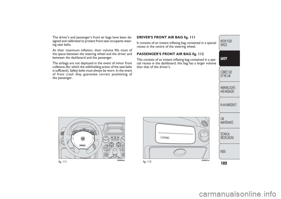
DRIVER’S FRONT AIR BAG fig. 111
It consists of an instant inflating bag contained in a special
recess in the centre of the steering wheel.
PASSENGER’S FRONT AIR BAG fig. 112
This consists of an instant inflating bag contained in a spe-
cial recess in the dashboard: this bag has a larger volume
than that of the driver’s. The driver’s and passenger’s front air bags have been de-
signed and calibrated to protect front seat occupants wear-
ing seat belts.
At their maximum inflation, their volume fills most of
the space between the steering wheel and the driver and
between the dashboard and the passenger.
The airbags are not deployed in the event of minor front
collisions (for which the withholding action of the seat belts
is sufficient). Safety belts must always be worn. In the event
of front crash they guarantee correct positioning of
the passenger.
091-110 PANDA EN 7-10-2009 13:46 Pagina 105