Rear FIAT PUNTO 1998 176 / 1.G Service Manual
[x] Cancel search | Manufacturer: FIAT, Model Year: 1998, Model line: PUNTO, Model: FIAT PUNTO 1998 176 / 1.GPages: 225, PDF Size: 18.54 MB
Page 117 of 225
3*2 Cooling, heating and ventilation systems
4 If the motor operates when tested as described, (he fault must lie In the engine wring harness or the temperature sensor. The temperature sensor/switch can be tested as described in Section 6. Any further fault Diagnosis should be referred to a suitably-equipped Fiat dealer - do not attempt to test
Ihe
electronic control unit.
Removal 5 Disconnect the battery negative terminal (refer to D/scon oecf/ng the battery in the Reference Section of this manual). 6 On diesel engine models, unbolt the relay bracket from the side of the battery tray to improve access. On 1242 cc {16-valve) petrol engine models, remove the air cleaner and
inset
ducts as described in Chapter 4B. 1 Disconnect the motor wiring connectorfs). 8 Unbolt the shroud from the rear of the ratiator. then lift out the cooling fan assembly. Refitting 9 Refitting is a reversal of removal
6 Cooling fan switch -testing, removal and refitting ^
Testing 1 The switch is threaded into the lower left
nand
comer of the radiator. 2 The switch can be tested by removing it,
and
checking that the switching action occurs
at
the correct temperature {heat the sensor in a container of water, and monitor the temperature with a thermometer). 3 There should be no continuity between the switch terminals, until Ihe specified cooling fan cut-In temperature Is reached, when continuity (and zero resistance) should exist between the terminals.
Removal 4 Disconnect the battery negative terminal refer to Disconnecting the battery in the Reference Section of this manual). 5 Allow the engine to cool completely, then drain the cooling system as described in Chapter 1Aor 1B. 6 Disconnect the wiring plug from the sensor.
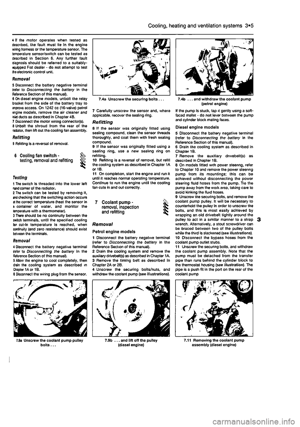
bolts...
7 Carefully unscrew the sensor and. whore applicable, recover the sealing ring. Refitting 8 If the sensor was originally fitted using sealing compound, clean the sensor threads thoroughly, and coat them with fresh sealing compound. 9 If the sensor was originally fitted using a sealing ring, use a new sealing ring on refitting. 10 Refitting is a reversal of removal, but refill the cooling system as described in Chapter 1A or 18. 11 On completion, start the engine and run it until it reaches normal operating temperature. Continue to run the engine until the cooling fan cuts in and out correctly.
7 Coolant pump • & removal, inspection 5 and refitting
Removal
Petrol engine models 1 Disconnect the battery negative terminal (refer to Disconnecting the battery in the Reference Section of this manual). 2 Drain the cooling system and remove the auxiliary drivebett(s) as described In Chapter 1 A. 3 Remove the timing belt as described In Chapter 2A or 28. 4 Unscrew the securing bolts/nuts, and withdraw the coolant pump (see illustrations).
7.9b ... and lift off the pulley (diesel engine)
(petrol engine) If the pump Is stuck, tap it gently using a soft-faced mallet - do not lever between the pump and cylinder block mating faces.
Diesel engine models 5 Disconnect the battery negative terminal (refer to D/s connecting the battery in the Reference Section of this manual). 6 Drain the cooling system as described in Chapter 1B. 7 Remove the auxiliary drivebelt(s) as descnbed In Chapter 1B. 6 On models fitted with power steenng, refer to Chapter 10 and remove the power steering pump from its mountings; this can be achieved without disconnecting the power steering fluid hoses from the pump. Tie the pump away from the work area, taking care to avoid kinking the fluid hoses. 9 Unscrew the securing bolts, and remove the coolant pump pulley. It will be necessary to counterhold the pulley In order to unscrew the bolts, and this is most easily achieved by wrapping an old drivebelt tightly around the pulley to act in a similar manner to a strap 3 wrench. Alternatively, a stout screwdriver can be braced between two of the pulley bolts while the third is slackened (see illustrations). 10 Disconnect ihe bypass hoses from the coolant pump outlet stubs. 11 Unscrew the securing bolts, and withdraw the coolant pump assembly. Note that the pump must be detached from the transfer pipe than runs behind the cylinder block to the thermostat housing (see illustration). The pipe is a push fit in the port on the rear of the coolant pump
7.11 Removing the coolant pump assembly (diesel engine)
Page 118 of 225
3*2 Cooling, heating and ventilation systems
12 If tho pump is stuck, tap It gently using a soft-faced mallet • do not lever between the pump and cylinder block mating faces.
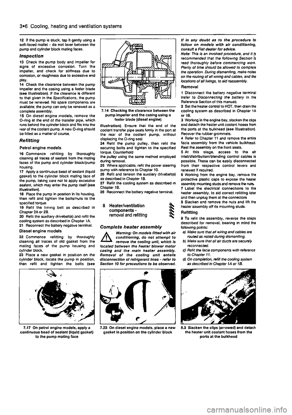
Inspection 13 Check the pump body and impeller for signs of excessive corrosion. Turn the impeller, and check for stiffness due to corrosion, or roughness due to excessive end play. 14 Check the clearance between the pump Impeller and the casing using a feeler blade (see Illustration). If the clearance is different to that given In the Specifications, the pump must be renewed. No spare components are available; the pump can only be renewed as a complete assembly. 15 On diesel engine models, remove the O-rlng at the end ol the transfer pipe, which runs behind Ihe cylinder block and fits Into the rear of the coolant pump. A new O-rlng should be fitted as a matter of course.
Refitting
Petrol engine models 16 Commence refitting by thoroughly cleaning all traces of sealant from the mating faces of the pump and cylinder block/pump housing. 17 Apply a continuous bead of sealant {liquid gasket) to the cylinder block mating face of the pump, taking care not to apply excessive sealant, which may enter the pump itself (see Illustration). 18 Place the pump In position In Its housing, then refit and lighten the bolts/nuts to the specified torque. 19 Refit the liming belt as described In Chapter 2A or 28. 20 Refit the auxiliary drivebeltfs) and refill the cooling system as described in Chapter
t
A. 21 Reconnect Ihe battery negative terminal. Diesel engine models 22 Commence refitting by thoroughly cleaning all traces of old gasket from the mating faces of the pump housing and cylinder block. 23 Place a new gasket in position on (he cylinder block, locate the pump in position, then refit and tighten the bolts (see
7.17 On petrol engine models, apply a continuous bead of sealant (liquid gasket) to the pump mating face
pump Impeller and the casing using a feeler blode (diesel engine) illustration). Ensure that the end of the coolant transfer pipe seats firmly In tho port at the rear of the coolant pump, without displacing the O-ring seal. 24 Refit Ihe pump pulley, then refit the securing bolts and tighten to the specified torque. Counterhofd the pulley using the same method employed during removal. 25 Where applicable, refit the power steering pump with reference to Chapter 10. 26 Refit and tension the auxiliary drivebelt(s) as described in Chapter 18. 27 Refill (he cooling system as desenbed in Chapter 1B. 28 Reconnect the battery negative terminal.
8 Heater/ventilation components - § removal and refitting
Complete heater assembly
A
Warning: On mode's fitted with air conditioning, do not attempt to remove the cooling unit, which Is located between the heater blower motor casing and the main heater assembly. Romovat of the cooling unit entails disconnection of refrigerant lines - refer to Section 10 for precautions to be observed.
rfJS
8.3 Slacken the clips (arrowed) and detach the heater unit coolant hoses from the ports at the bulkhead
Page 123 of 225
4A*2 Fuel system - single-point petrol Injection models
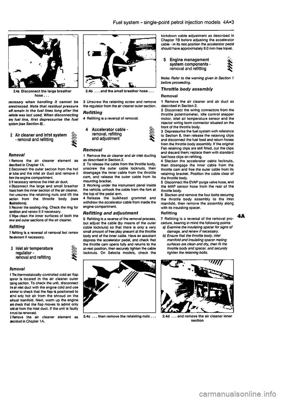
2.4a Disconnect the large breather hose... ziecessary when handling it cannot be mrstressed. Note that residual pressure
wttf
remain in the tuei lines long after the wh/cte was last used, When disconnecting any fuel line, first depressurise the fuel
system
(see Section 8).
2 Air cleaner and intet system • removal and refitting
1
Accelerator cable -removal, refitting and adjustment l
Removal 1 Remove the air cleaner element as described in Chapter 1A. 2 Disconnect the outer section from the hot
air
tube and the inlet air duct and remove it
from
the engine compartment. 3II necessary remove the inlet air duct. 4 Disconnect Ihe large and small breather
roses
from the inner section of the air cleaner, tftsn unscrew the retaining nuts and lift the section from the throttle body (see lustrations).
5
Recover the sealing ring. Check the ring for condition and renew it if necessary.
6
Wipe clean the inner surfaces of both the merand outer sections of the air cleaner. Refitting 7 Refitting Is a reversal ol removal but renew
tie
element
H
necessary.
3 Inlet air temperature regulator -removal and refitting
Removal t
The
thermostatically-controlled cold air flap cpener is located in the air cleaner outer ttsrig section. To check the unit, disconnect
ire air
inlet duct with the engine cold and use imrrorto check that the flap Is positioned to aJmit only hot air from the shroud on the utaust manifold. Next, warm up the engine
and
check that the flap moves to admit only sett air from the inlet duct. If the unit is faulty fl must be renewed.
2
Remove the air cleaner element as •senbod in Chapter
1
A.
kickdown cable adjustment as described in Chapter 7B before adjusting the accelerator cable • in its rest position the accelerator pedal should have approximately 8.0 mm free travel.
5 Engine management system components -removal and refitting I
2.4b ... and the small breather hose ...
3 Unscrew the retaining screw and remove the regulator from the air cleaner outer section.
Refitting 4 Refitting is a reversal of removal.
Removal 1 Remove the air cleaner and air inlet ducting as desenbed in Section 2. 2 To release the cable from the throttle body, unscrew the outer cable locknuts, then disengage the inner cable from the throttle cam, and release the outer cable from its mounting bracket. 3 Working under the instrument panel inside the vehicle, unhook the cable from the fork at the top of the pedal arm. 4 Release the bulkhead grommet and withdraw the accelerator cable from Inside the engine compartment.
Refitting and adjustment 5 Refitting is a reverse of the removal process, but adjust the cable (by means of the outer cable locknuts) so that there is only a very small amount of free play present at the throttle body end of the inner cable. Have an assistant depress the accelerator pedal, and check that the throttle cam opens fully and returns to the at-rest position, then secureJy tighten the cable locknuts. On Selecta models, check the
Note: Refer to the warning given in Section 1 before proceeding. Throttle body assembly
Removal 1 Remove the air cleaner and air duct as desenbed in Section 2. 2 Disconnect the wiring connectors from the throttle potentiometer, idle control stepper motor, inlet air temperature sensor and the injector wiring loom connector situated on the front of the throttle body. 3 Depressurise the fuel system with reference to Section 8, then release the retaining clips and disconnect the fuel feed and return hoses from the throttle body assembly, if the original Fiat retaining clips are still fitted, cut the clips and discard them; replace them with standard luel hose clips on refitting. 4 Slacken the accelerator cable locknuts, then disengage the inner cable from the throttle cam and froe tho outer cable from its retaining bracket. Position the cable clear of the throttle body. 5 Disconnect the EVAP purge valve hose, and the MAP sensor hose from the rear of the throttle body. 6 Slacken and remove the four bolts securing the throttle body assembly to tho Inlet manifold, then remove the assembly along with its insulating spacer. Refitting 7 Refitting is a reversal of the removal pro-cedure, bearing in mind the following points: a) Examine the insulating spacer for signs of damage, and renew //necessary, b) Ensure that the throttle body, inlet manifold and insulating spacer ma ting surfaces are clean and dry, then fit the throttle body and spacer, and securely tighten the retaining bolts.
2.4c ... then remove the retaining nuts. 2.4d ... and remove the air cleaner inner section
Page 125 of 225
Ihe right-hand front roadwheel and the protective plastic cover under the wheelarch. 37 Disconnect the sensor wiring plug on the front of the engine. 38 Detach the sensor from its mounting. Refitting 39 After refitting Ihe sensor use a feeler blade to check that the gap between sensor and the serrated part of the crankshaft pulley Is between 0.5 and 1.S mm. No adjustment is possible and if the gap is incorrect the sensor and pulley should be checked for possible damage.
Electronic control unit (ECU)
Removal Note: 77ie engine management system has a (earning capability which allows the ECU to store details of the engine's running
characteristics
in its memory,
This
memory
will
tie erased by the disconnection of the battery
cables,
with the resuit that the engine may idle
roughly,
or lack performance for a while, until
the
engine's characteristics are re-teamt. 40 The ECU {electronic control unit) is located on the right-hand Inner wing (see illustration). The 3-pin socket by the ECU is for connection of diagnostic test equipment. 41 Disconnect the battery negative terminal (refer to D/sconnecffng the battery in the Reference Section of this manual). 42 Disconnect the ECU wiring connector, then undo the retaining nuts and remove the unit from the bracket In the engine compartment. Refitting 43 Refitting Is a reversal of removal making sure that the wiring connector is securely reconnected. Inertia safety switch
Removal 44 The inertia safety switch is located by the left-hand side passenger seat. First pull back
the
carpet for access. 45 Disconnect the wiring then unbolt the switch. Refitting 48 Refitting is a reversal of removal.
Fuel injection system relays
Removal 47 The fuel injection system relay is located under a plastic cover on the bulkhead. The MAP sensor is also located under the same cover. 48 Two separate relays are incorporated in the single housing; the left-hand relay has a 5 amp fuse and the right-hand relay has a 25 amp fuse. The main purpose of the relays is to supply current to the fuel pump, ignition coils, oxygen sensor. Injectors and EVAP solenoid. The main relay is controlled by the ignition switch.
4A*2 Fuel system - single-point petrol Injection models
6 Fuel pump/fuel gauge sender unit -removal and refitting
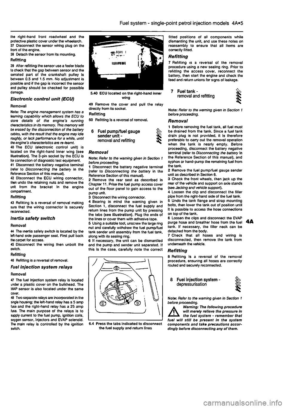
Removal Note: Refer to the warning given in Section 1 before proceeding. 1 Disconnect the battery negative terminal (refer to Disconnecting the battery in the Reference Section of this manual). 2 Remove the rear seat as described in Chapter 11. Prise the fuel pump access cover out of the floor panel to gain access to the pump unit. 3 Disconnect the wiring connector. 4 Bearing in mind the warning given in Section t, disconnect the fuel supply and return lines from the pump unit by pressing the tabs (see illustration). Plug the ends of the lines or cover them with adhesive tape. 5 Using a suitable toot, unscrew the large ring nut and carefully withdraw the fuel pump/fuel tank sender unit assembly from the fuel tank, along with its sealing ring. 6 If necessary, the unit can be dismantled and the pump and sender unit separated. If this is the case, carefully note the correct
fitted positions of oil components while dismantling the unit, and use these notes on reassembly to ensure that all items are correctly fitted.
Refitting 7 Refitting is a reversal of the removal procedure using a new sealing ring. Prior to refitting the access cover, reconnect the battery, then start the engine and check the feed and return unions for signs of leakage.
5.40 ECU located on the right-hand inner wing 49 Remove the cover and pull the relay directly from its socket. Refitting 50 Refitting Is a reversal of removal.
7 Fuel tank -removal and refitting
6.4 Press the tabs Indicated to disconnect the fuel supply and return tines
Note: Refer to the warning given in Section 1 before proceeding.
Removal 1 Before removing the fuel tank, all fuel must be drained from the tank. Since a fuel tank drain plug is not provided, it is therefore preferable to carry out the removal operation when the tank is nearly empty. Before proceeding, disconnect the battery negative terminal (refer to Disconnecting the battery In the Reference Section of this manual), and syphon or hand-pump the remaining fuel from the tank. 2 Remove the fuel pump/fuel gauge sender unit as described in Section 6. 3 Chock the front wheels, then jack up the rear of the vehicle and support on axle stands (see Jacking and vehicle support). 4 Loosen the clip and disconnect the filler pipe from the nght-hand side of the fuel tank. 5 Undo the tank flange and strap mounting bolts, then lower the tank out of position until It is possible to access the hose connections on top of the tank. 6 Loosen the clips and disconnect the EVAP purge hose and breather hose from the fuel tank. If necessary, the filler neck can be detached from the body. 7 Check that all hoses and wiring is disconnected, then remove the tank from underneath the vehicle. Refitting 8 Refitting is a reversal of the removal procedure, ensuring all hoses are correctly routed and securely reconnected.
8 Fuel injection system - ^ depressurisation
Note: Refer to the warning given In Section t before proceeding.
A
Warning; The following procedure will merely relievo the pressure in the fuel system • remember that fuel will still be present In the system components and take precautions accor-dingly before disconnecting any of them.
Page 126 of 225
4A*2 Fuel system - single-point petrol Injection models
1 The luel system referred to In this Section is defined as the tank-mounted fuel pump, the fuel litter, the throttle body and pressure regulator components, and the metal pipes and flexible hoses of the fuel lines between these components. All ihese contain fuel which will be under pressure while the engine Is running and/or while tha Ignition is switched on. The pressure will remain for some time after tho ignition has been switched off, and must be relieved before any of these components are disturbed (or servicing work. 2 Disconnect the battery negative terminal (refer to D/sconnecf/ngr the battery in the Reference Section of this manual), 3 Place a container beneath the relevant connection/union to be disconnected, and have a large rag ready to soak up any escaping fuel not being caught by the container. 4 Slowly loosen the connection or union nut (as applicable) to avoid a sudden release of pressure, and wrap tho rag around the connection to catch any fuel spray which may be expelled. Once the pressure is released, disconnect the fuel line, and Insert plugs to minimise fuel loss and prevent the entry of dirt Into the fuel system.
9 Inlet manifold -removal and refitting ^
Note: Refer to the warning given In Section 1 before proceeding.
Removal 1 Remove the throttle body assembly as described in Section 5. 2 Drain the cooling system as described in Chapter 1A. 3 Disconnect the winng connector from the coolanl temperature sensor (situated on the left-hand sidB of the manifold). 4 Undo the bolt securing the accelerator cable mounting bracket to the manifold, and position it clear of the manifold. 5 Slacken the retaining clip and disconnect tha coolant hose from the rear of the manifold. 6 Disconnect the brake vacuum hose. 7 Undo the seven manifold retaining nuts and
10.2 The diagnostic connector la located behind the ECU bolts, and remove (he manifold from the engine. Remove the gasket and discard It; a new one should be used on refitting.
Refitting 8 Refitting is a reverse of the removal procedure, noting the following points: a) Ensure that the manifold and cylinder head mating surfaces are clean and dry, and fit a nev/ manifold gasket. Refit the manifold and securely tighten Its retaining nuts. b) Ensure that all relevant hoses are reconnected fo their original positions and are securely held (where necessary) by the retaining clips. c) Refit the throttle body assembly with reference to Section S. d) On completion, refill the cooling system as described In Chapter 1A.
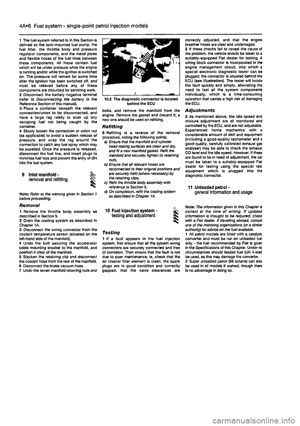
correctly adjusted, and that the engine breather hoses are clear and undamaged. 2 If these checks fall to reveal the cause of the problem, the vehicle should be taken to a suitably-equipped Fiat dealer for testing. A wiring block connector Is Incorporated In the engine management circuit, into which a special electronic diagnostic tester can be plugged; the connector is situated behind the ECU (see Illustration). The tester will locate the fault quickly and simply, alleviating the need to test all the system components Individually, which is a time-consuming operation that carries a high risk of damaging the ECU.
Adjustments 3 As mentioned above, the idle speed and mixture adjustment are all monitored and controlled by the ECU, and are not adjustable Experienced home mechanics with a considerable amount of skill and equipment (including a good-quality tachometer and a good-quality, carefully calibrated exhaust gas analyser) may be able to check the exhaust CO level and ihe idle speed. However, If thes* are found lo be in need of adjustment, the car must be taken to a suitably-equipped Flat dealer for testing using the special test equipment which is plugged into the diagnostic connector.
11 Unleaded petrol -general Information and usage
10 Fuel injection system - & testing and adjustment S
Testing 1 If a fault appears in the fuel injection system, first ensure that all the system winng connectors are securely connected and free of corrosion. Then ensure that the fault Is not due to poor maintenance; ie, check that the air cleanor fitter element is clean, the spark plugs are In good condition and correctly gapped, that tho valve clearances are
Note: The information given in this Chapter
is
correct at the time of writing. If updated Information is thought to be required, check with a Fiat dealer. If travelling abroad, consult one of the motonng organisations (or a similar authority) for advice on the fuel available. 1 All petrol models are fitted with a catalytic converter and must be run on unleaded fuel only - the fuel recommended by Flat is given In the Specifications of this Chapter. Under no circumstances should leaded fuei (UK 4-slar) be used, as this may damage the converter. 2 Super unleaded petrol (98 octane) can also be used in all models if wished, though there is no advantage in doing so.
Page 131 of 225
4A*2 Fuel system -
single-point
petrol Injection models
17 Have an assistant depress the accelerator pedal and check that the throttle cam opens luily and returns smoothly to its stop. If necessary, reposition the spring clip In the next outer cable groove and recheck the throttle operation. 18 Refit the remainder of the disturbed components.
5 Engine management
system
^ components
(1242
cc, 8-vatve § engines) -
removal and refitting
^
Note: Refer to the warning given In Section T
before
proceeding.
Throttle body assembly
Removal 1 Remove the air cleaner and inlet air duct as described in Section 2. 2 Disconnect the wiring connectors from the throttle potentiometer, the idle control stepper motor and the inlet air temperature sensor. 3 Slacken the accelerator cable locknuts, then disengage the inner cable from the throttle cam and free the outer cable from its retaining bracket. Position the cable clear of the throttle body. 4 Unclip and disconnect the EVAP purge valve hose, and Ihe MAP sensor hose from the rear of the throttle body then, where applicable, disconnect the fuel pressure regulator vacuum hose from the front of the throttle body. 5 Slacken and remove the four bolts securing the throttle body assembly to the inlet manifold, then remove the assembly along with its insulating spacer. Refitting 6 Refitting is a reversal of the removal pro-cedure. bearing in mind the following points: 4! Examine the Insulating spacer for signs of damage, and renew If necessary. b) Ensure the throttle body, inlet manifold and insulating spacer mating surfaces are clean and dry, then fit the throttle body and spacer, and securely tighten the retaining bolts. c) Ensure ail hoses are correctly reconnected and, where necessary, /her their retaining clips are securely tightened. d) Adjust the accelerator cable as described in Section 4.
Fuel
rail and injectors
Removal 7 Disconnect the battery negative terminal (refer to Disconnecting tho battery in the Reference Section of this manual). 6 Remove the throttle body assembly as described earlier in this Section, however it is only necessary to move the unit to one side for access to the fuel rail and therefore it Is unnecessary to disconnect the accelerator caWe and hoses etc.
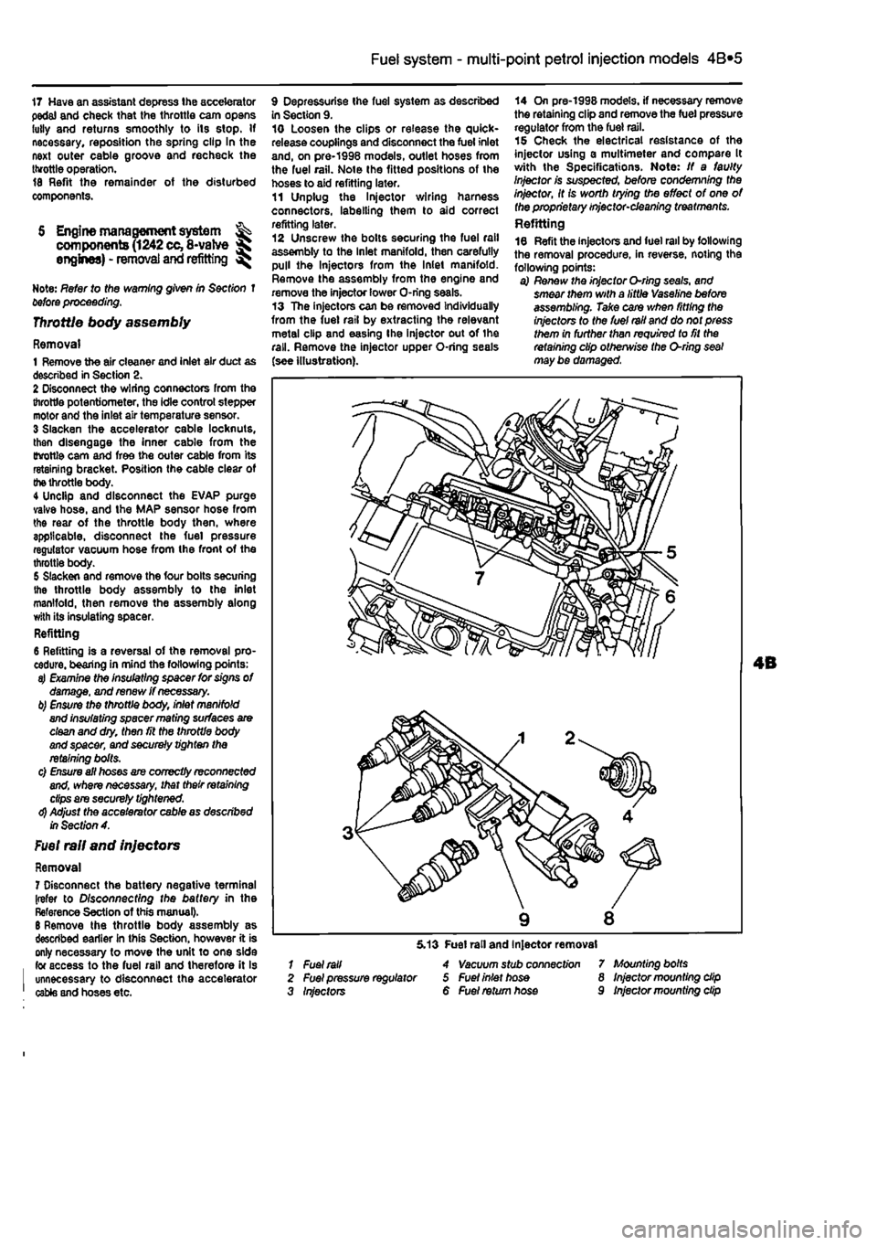
9 Depressurise Ihe fuel system as described in Section 9. 10 Loosen the clips or release the quick-release couplings and disconnect the fuel inlet and, on pre-1998 models, outlet hoses from the fuel rail. Note the fitted positions of the hoses to aid refitting later. 11 Unplug the ln}ector wiring harness connectors, labelling them to aid correct refitting later. 12 Unscrew the bolts securing the fuel rail assembly to the Inlet manifold, then carefully pull the Injectors from the Inlet manifold. Remove the assembly from the engine and remove the injector lower O-ring seals. 13 The injectors can be removed Individually from the fuel rail by extracting the relevant metal clip and easing Ihe injector out of the rail. Remove the injector upper O-ring seals (see illustration).
14 On pre-1998 models, if necessary remove the retaining clip and remove the fuel pressure regulator from the fuel rail. 15 Check the electrical resistance of the injector using a multimeter and compare It with the Specifications. Note: If a faulty Injector is suspected, before condemning the injector, It is worth trying the effect of one of the proprietary injector-cleaning treatments. Refitting 16 Refit the injectors and fuel rail by following the removal procedure, in reverse, noting the following points: a) Renew the injector O-rlng seals, and smear them with a little Vaseline before assembling. Take care when fitting the injectors to the fuel rail and do not press them in further than required to fit the retaining clip otherwise the O-ring seal may be damaged.
1 Fuel rail 2 Fuel pressure regulator 3 Injectors
5.13 Fuel rail and Injector removal 4 Vacuum stub connect/on 5 Fuel inlet hose 6 Fuel return hose
7 Mounting bolts 8 Injector mounting dip 9 Injector mounting dip
Page 134 of 225
4A*2 Fuel system -
single-point
petrol Injection models
Refitting 37 Refitting Is a reversal of removal making sure that the wiring connector is securely reconnected.
Inertia safety switch 36 Refer to Chapter 4A, Fuel injection system relays Removal 39 The fuel injection system twin relay Is located under a plastic cover on the engine compartment bulkhead. 40 The main purpose of the relay Is to supply current to the fuel pump, ignition coils, oxygen sensor, Injectors and EVAP solenoid. The relay is controlled by the ignition switch. A15 amp fuse, protecting ihe fuel pump, oxygen sensor and EVAP solenoid is located adjacent to the relay. 41 Remove the cover and pull the relay directfy from Its socket. Refitting 42 Refitting is a reversal of removal.
7 Fuel pump and fuel gauge sender unit - JK removal
and
refitting ^
Removal Note: Refer fo (he warning given in Section 1 before proceeding. 1 Disconnect the battery negative terminal (refer to Disconnecting the battery In the Reference Section of this manual). 2 Depreasurise the fuel system as described in Section 9. 3 Remove the rear soat as described In Chapter 11. Prise the fuel pump access cover out of the floor panel to gain access to the pump unit. On later models, undo the three retaining screws to release the cover. 4 Disconnect the wiring connector. 5 Bearing In mind the warning given In Section t, disconnect Ihe fuel supply and, where applicable, the return lines from tho pump unit by pressing the tabs. Plug the ends of the lines or cover them with adhesive tape. 6 Using a suitable tool, unscrew the large ring nut and carefully withdraw the fuel pump/fuel tank sender unit assembly from the fuel tank, along with its sealing rtng. 7 If necessary, the unit can be dismantled and the pump and sender unit separated. If this is (he case, carefully note the correct fitted positions of all components while dismantling the unit, and use these notes on reassembly to ensure that all items are correctly fitted.
Refitting 8 Refitting is a reversal of the removal procedure using a new sealing ring. Prior to refitting the access cover, reconnect the battery, then start the engine and check the fuel line unlon(s) (or signs of i
Fuel
tank -removal and refitting
Refer to Chapter 4A.
9 Fuel injection system -depressurisatton
Note: Refer to the warning given In Section 1 before proceeding.
A
Warning: The following procedure will merely relieve the pressure In the fuel system • remember that fuel will still be present In the system components and take precautions accord-ingly before disconnecting any of them. 1 The fuel system referred to in this Section is defined as the lank-mounted fuel pump, tha fuel filter, the fuel rail, the fuel injectors, and the metal pipes and flexible hoses of the fuel lines between these components. All these contain fuel which will be under pressure while the engine Is running and/or while the Ignition is switched on. The pressure will remain for some time after the Ignition has been switched off. and must be relieved before any of these components are disturbed for servicing work. 2 Disconnect the battery negative terminal (refer to Disconnecting the battery In the Reference Section of this manual). 3 Have a large rag ready to cover the union to be disconnected and, if possible, place a con-tainer beneath the relevant connection/union. 4 Slowly loosen the connection or union nut (as applicable) to avoid a sudden release of pressure, and ensure that the rag is wrapped around the connection to catch any fuef spray which may be expelled. Once the pressure is released, disconnect the fuel line, and Insert plugs to minimise fuel loss and prevent the entry of dirt Into the fuel system. Note that on later models, quick-release fuel couplings are used on many of the fuel line connections. To release these couplings, depress the two clips on the side of the coupling while keeping the fuel line pushed In. With the clips depressed, slowly withdraw the fuel line from the coupling allowing the fuel pressure to release, then withdraw the fuel line fully.
10 Inlet manifold-removal
and
refitting
Note: Refer fo the warning given in Section 1 before proceeding.
1242 cc (8-valve) engines
Removal 1 Remove ihe throttle body assembly as described in Section 5.
2 Remove the fuel rail and injectors at described in Section 5. 3 Drain the cooling system ss described n Chapter 1A. 4 Disconnect the wiring connector from ih* coolant temperature sensor (situated on it* left-hand side of the manifold). 5 Undo the bolt securing the accelerator cable mounting bracket to the manifold, am position it clear of the manifold. 6 Slacken the retaining clip and disconnect the coolant hose from the rear of the mandold 7 Disconnect the brake vacuum hose, 6 Undo the seven manifold retaining nuisw bolts, and remove the manifold from tta engine. Remove the gasket and discard tti new one should be used on refitting. Refitting
9 Refitting is a reverse of the removjf procedure, noting the following points: a) Ensure that the manifold and cylinder lim mating surfaces are dean and
dry.
and fill new manifold gasket. Refit the
manifold
and securely tighten Its retaining
nuts.
b) Ensure all relevant hoses are recorwscfed fo their original positions and are
sacurtfy
held (Where necessary; by the
retaining
clips. c) Refit the fuel rail and injectors, and
the
throttle body assembly with
reference to
Sect/on 5. d) On completion, refill the cooling
system
as described in Chapter 1A. 1242 cc (16-valve) engines
Removal 10 Disconnect the battery negative ternnncf (refer to Disconnecting the battery in ths Reference Section of this manual). 11 Remove the resonator, air cleaner and inlet air duct as described In Section 2. 12 Drain the cooling system as described r, Chapter 1A. 13 Free the accelerator inner cable from IN throttle cam. remove the outer cable spring dip. then pull the outer cable out from itt mounting bracket rubber grommet. 14 From the side of the throttle boOf, disconnect the wiring connectors from the throttle potentiometer and the Idle contrd stepper motor. Disconnect the coolant temperature sensor wiring connector located in the Inlet manilold below the throttie bodr, and disconnect the brake servo vacuum hose. 15 Disconnect Ihe wiring connectors for the fuel in|ector harness and the Intake a* temperature/pressure sensor, thtn disconnect the fuel pressure regulator vacuum hose and the EVAP purge valve
hose
(see illustration). 16 Undo Ihe two bolts securing the plastic Inlet manifold upper section to the lower section. Release the spark plug HT lead from the location groove in the manifold upper section, then lift Ihe upper section, complete with throttle body, off the engine. Recover
the
O-rings from the manifold pons.
Page 136 of 225
4C»1
Chapter 4 PartC:
Fuel system - diesel models
Contents
Accelerator cable • removal, refitting and adjustment 3 Air cleaner and inlet system • removal and refitting 2
AJr
cleaner filter element - renewal See Chapter IB Fuet filter renewal See Chapter 1B Fuel gauge sender unit • removal and refitting 10 Fuel injection pump • removal and refitting 5 Fuel injectors - testing, removal and refitting 9
Fuel
system • priming and bleeding 4
Fuel
tank - removal and refitting 11 General Information and precautions 1
Idle speed - checking and adjustment See Chapter 1B Injection timing • checking methods 6 injection timing {Bosch fuel Injection pump) • checking and adjustment 7 Injection timing (Lucas fuel Injection pump) - checking and adjustment 8 Inlet manifold - removal and refitting 12 Turbocharger - description and precautions 13 Turbocharger - examination and renovation 15 Turbocharger - removal and refitting 14
Degrees of difficulty
Easy,
suitable for novice
with Ittle
p experience sS^
Fairly easy, suitable (or beginner with some experience
Fairly tfifficuit, suitable
for
competent ^
DIY
mechanic
Difficult, suitable
for ^ experienced DIY jR mechanic ^
Very difficult, ^ sutable for expert
DIY
S or professional ^
Specifications
General System type
Firing order
Injection pump (Bosch VE) Direction of rotation Static timing: Engine position Pump timing measurement Maximum engine speed
Injection pump (Lucas/CAV FT08) Direction of rotation Static timing: Engine position Pump timing measurement Maximum engine speed
injectors Type Opening pressure: Bosch Lucas: New After running in
RPM sensor Sensor-to-flywheel ring gear teeth gap — Winding resistance
Rear-mounted fuel tank, distributor fuel injection pump with integral transfer pump. Indirect Injection, Turbocharger on TDS, TD and TDSX models 1-3-4-2 (No
1
at timing belt end of engine)
Clockwise, viewed from sprocket end
No
1
piston at TDC 0.93 ± 0.05 mm 5200 to 5300 rpm
Clockwise, viewed from sprocket end
No 1 piston at TDC 0° ± 1° TDC (Note: Value shown on pump - see text} 5150150 rpm
Pintle
150 to 158 bar
124 to
131
bar 116lo123 bar
0.25 to 1.3 mm 680* 100 ohms
Page 137 of 225
Fuel system - diesel models 4C*3
Torque wrench settings Nm Ibfft Fuel injection pump roar bracket .. . 29 21 Fuel Injection pump .... 25 18 Fuel Injectors 41 Fuel pipe union nuts .... 30 22 Inlet manifold .... 24 18 Lower oil tiller mounting and injection pump mounting nut ..... .... 71 S2 Turbocnarger to exhaust manifold .... <10 30 Upper Dtl filter mounting end injection pump mounting nut 98 72
1 General information and precautions
General information The fuel system consists of a rear-mounted fust tank, a fuel filter with integral water separator, a fuel injection pump, in|eciors and associated components. A turbocharger is fitted to TDS, TD and TDSX models. Fuel Is drawn from the fuel tank to the fuel Injection pump by a vane-type transfer pump Incorporated in the fuel injection pump. Before reaching tho pump, the fuel passes through a fuel filter, where foreign matter and water aro removed. Excess fuel lubricates the moving components of the pump, and Is then returned to the tank. On turbo models with the Bosch fuel Injection systom, an eiectncally operated heater is incorporated In the fuel filter housing. The fuel injection pump is driven at half-crankshaft speed by the timing belt. The nigh pressure required to inject tho fuel into the compressed air in the swirl chambers Is achlovod by a cam plate acting on a single piston on the Bosch pumo, or by two opposed pistons forced together by rollers running in a cam ring on the Lucas (CAV) pump. Tlie fuel passes through acentral rotor with a single outlet drilling which aligns With ports leading to the Injector pipes. Fuel metering is controlled by a centrifugal governor, which reacts to accelerator pedal
position end engine speed. The governor is linked lo a metering valve, which increases or decreases the amount of fuel delivered at each pumping stroke. On turbocharged models, a separate device also Increases luel delivery with increasing boost pressure. Basic injection timing is determined when the pump is fitted. When the engine is running, it Is varied automatically to suit the prevailing engine speed by a mechanism which turns the cam plate or ring, Tho four fuel injectors proouco a homogeneous spray of fuel Into the swirl chambers located In the cylinder head. The Injectors are calibrated to open end close at critical pressures lo provide efficient and even combustion. Each injector needle is lubricated by fuel, which accumulates In the spring chamber and is channelled to the injection pump return hose by loak-off pipes Bosch or Lucas fuel system components mBy be fitted, depending on the model. Components from the latter manufacturer are marked either CAV. Roto-dlesel or Con-diesel. depending on their date and place of manufacture. With the exception of the fuel filter assembly, replacement components must be of tho same make as those originally fitted. Cold starting is assisted by preheater or glow plugs fitted to each swirl chamber. On the Bosch injection pump, an automatic cold Injection advance device operated through a thermal switch, advances the injection timing by Increasing the fuel pressure. The device operates at coolant temperatures below 55° C,
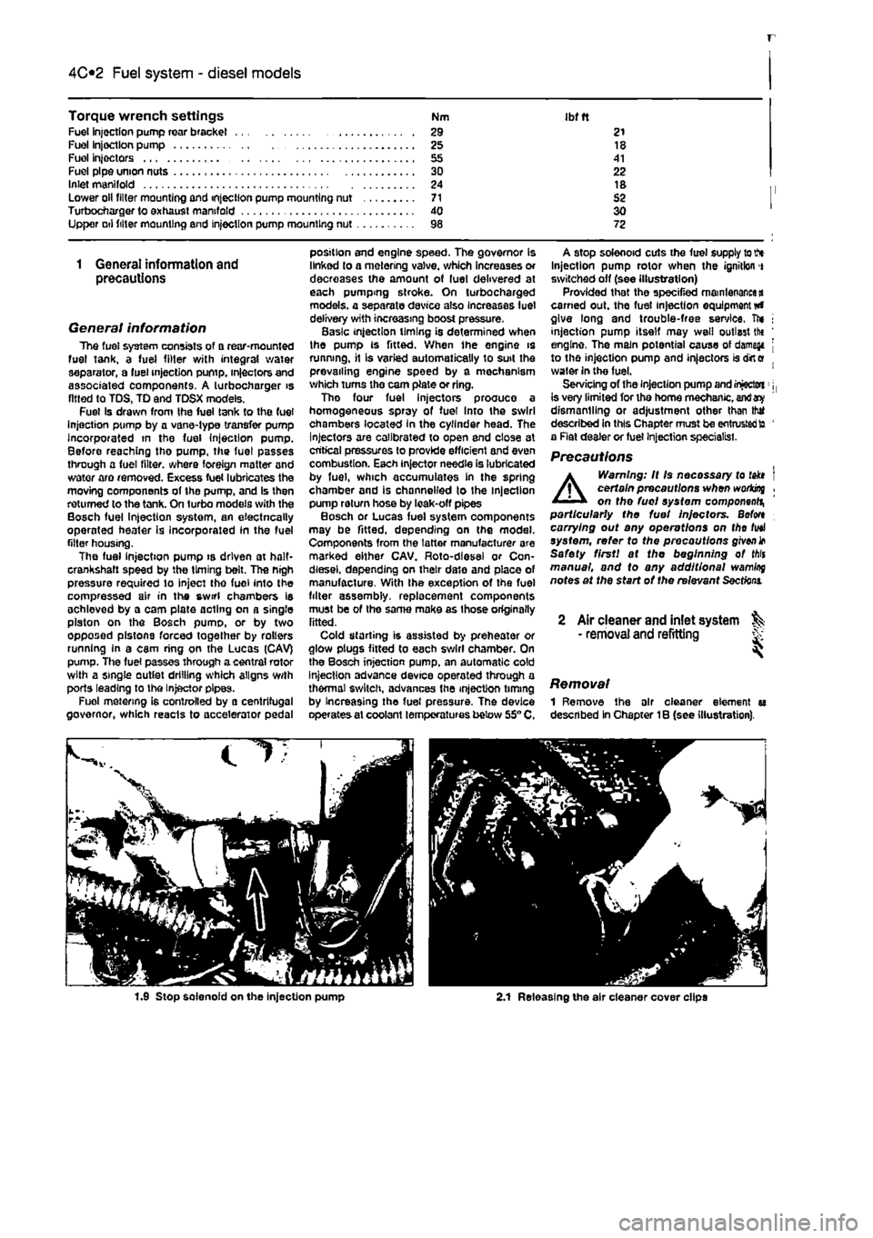
A stop solenoid cuts the fuel supply to V* Injection pump rotor when the ignition i switched off (see illustration) Provided that the specified maintenance* earned out. the fuel injection equipment #» give long and trouble-free service, ft* j injection pump itself may well outlast tlx ' engine, The main potential cause of damage j to the injection pump and injectors is dirt e water in the fuel. 1 Servicing of the injection pump and injectwi: j, is very limited for tho home mechanic, antf dismantling or adjustment other than thtf described In this Chapter must be entrusted to ' a Rat dealer or fuel Injection specialist.
Precautions
A
Warning: It Is necessary to takt I certain precautions when woriong , on the fuel system component^ particularly the fuel Injectors. Befon carrying out any operations on tho fuel system, refer to the precautions given* Safety first! at the beginning of Mis manual, and to any additional wamlrq notes at the start of the relevant
Sections.
2 Air cleaner and inlet system ^ • removal and refitting S
Removal 1 Remove the air cleaner element u described In Chapter 1B (see illustration).
1.9 Stop solenoid on the injection pump 2.1 Releasing the air cleaner cover clips
Page 139 of 225
Fuel system - diesel models 4C*3
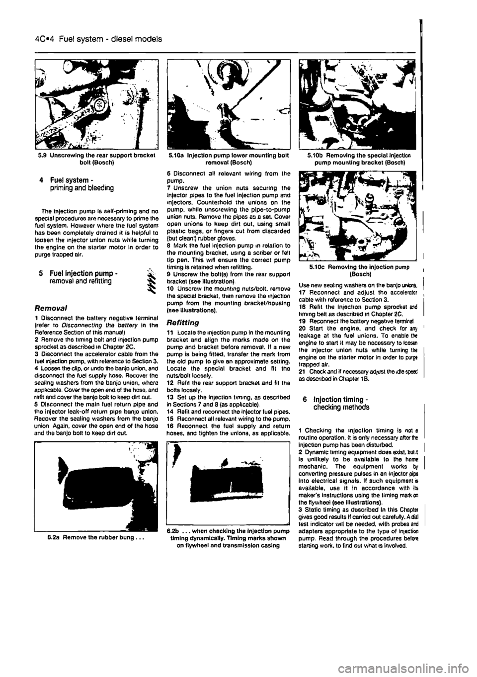
bolt (Bosch)
4 Fuel system -priming and bleeding
The Injection pump Is self-priming and no special procedures are necessary to prime the fuel system. However where the luei system has been completely drained it (s helpful to loosen the injector union nuts while turning the engine on the starter motor In order to purge trooped air.
S Fuel injection pump • removal and refitting 5
Removal 1 Disconnect the battery negative terminal (refer to Disconnecting the battery In the Reference Section of this manual) 2 Remove the timing belt and Injection pump sprocket aa described in Chapter 2C. 3 Disconnect the accelerator cable from the fuel injection pump, with reference to Section 3. 4 Loosen the clip, or undo the banjo union, and disconnect the fuel supply hose. Recover the sealing washers from the banjo union, where applicable. Cover the open end of the hose, and raflt and cover the banjo bolt to keep dirt out. 5 Disconnect the main fuel return pipe and the injector leak-off return pipe banjo union. Recover the sealing washers from the banjo union Again, cover the open end of the hose and the banjo bolt to keep dirt out.
6.2a Remove the rubber bung ...
k
5.10a Injection pump lower mounting bolt removal (Bosch) 6 Disconnect all relevant wiring from the pump. 7 Unscrew the union nuts securing the Injector pipes to the fuel Injection pump and injectors. Counterhold the unions on Ihe pump, while unscrewing the pipe-to-pump union nuts. Remove the pipes as a set. Cover open unions lo keep dirt out. using small plastic begs, or fingers cut from discarded (but clean!) rubber gloves. 8 Mark the fuel Injection pump in relation to the mounting bracket, using a scriber or felt tip pen. This will ensure Ihe correct pump timing is retained when refitting. 9 Unscrew the bolt(s) from Ihe rear support bracket (see illustration) 10 Unscrew the mounting nuts/bolt, remove the special bracket, then remove the injection pump from the mounting bracket/housing (see illustrations).
Refitting 11 Locate the injection pump In the mounting bracket and align the marks mode on the pump and bracket before removal. If a new pump is being fitted, transfer the mark from the old pump to give an approximate setting. Locate the special bracket and fit the nuts/bolt loosely. 12 Refil Ihe rear support bracket and fit the bolts loosely. 13 Set up the injection timing, as described In Sections 7 and 8 (as applicable). 14 Refil and reconnect the injector fuel pipes. 15 Reconnect all relevant wiring to the pump. 16 Reconnect the fuel supply and return hoses, and tighten the unions, as applicable.
6.2b ... when checking the injection pump timing dynamically. Timing marks shown on flywheel and transmission casing
5.10b Removing the special Injection pump mounting brackot (Bosch)
5.10c Removing tho injection pump (Bosch) Use new sealing washers on the banjo unions. 17 Reconnect and adjust the accelerator . cable with reference to Section 3. i 16 Refit the Injection pump sprocket end timing belt as described in Chapter 2C. I 19 Reconnect Ihe battery negative terminal 20 Start the engine, and check for any ' leakage at the fuel unions. To enable the engine to start It may be necessary to loos® the injector union nuts while turning the engine on the starter motor in order to porgt trapped air. 21 Check and if necessary adjust the idle speed as described in Chapter 1B.
6 injection timing -checking methods
1 Checking the injection timing Is not e routlno operation. It Is only necessary aftorth* Injection pump has been disturbed. I 2 Dynamic timing equipment does exist, bulit ' is unlikely to be available to the hame I mechanic. Tho equipment works by I converting pressure pulses in an Injector pips into electrical signals. If such equipment« available, use it In accordance with Its maker's instructions using the liming mark
on
the flywheel (see illustrations). 3 Static timing as described In this Chaptai gives good results If carried out carefully. A dial test indicator will be needed, with probes and adapters appropriate to the typo of infection pump. Read through the procedures beto starting work, to find out what ts Involved.