technical specifications FIAT SCUDO 2010 Owner handbook (in English)
[x] Cancel search | Manufacturer: FIAT, Model Year: 2010, Model line: SCUDO, Model: FIAT SCUDO 2010Pages: 210, PDF Size: 3.32 MB
Page 135 of 210
ENGINE
STARTING
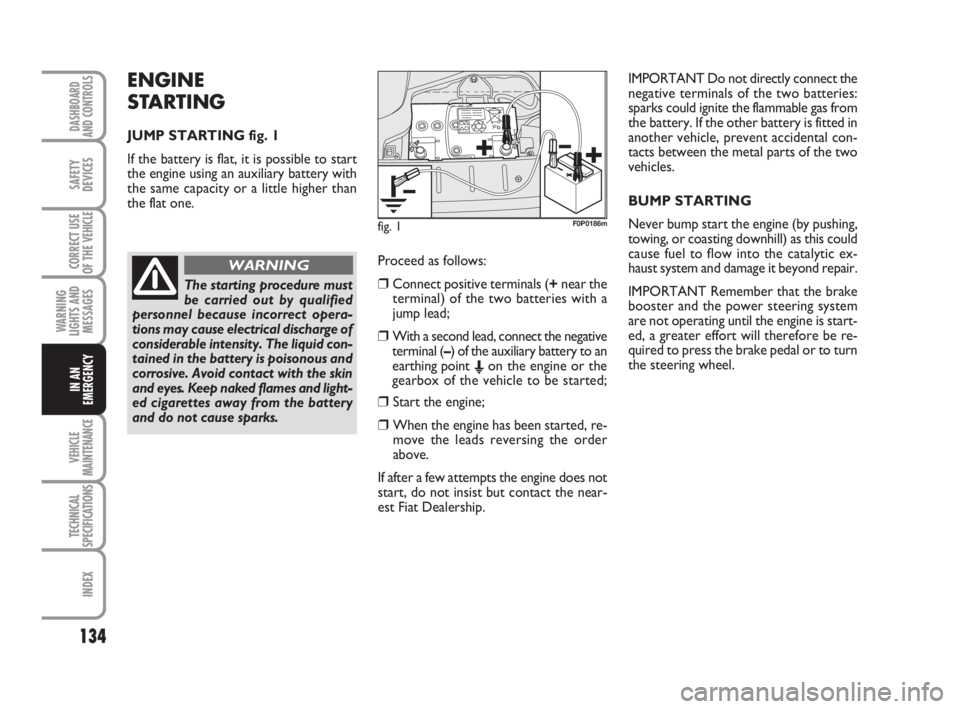
JUMP STARTING fig. 1
If the battery is flat, it is possible to start
the engine using an auxiliary battery with
the same capacity or a little higher than
the flat one.
134
WARNING
LIGHTS AND
MESSAGES
VEHICLE
MAINTENANCE
TECHNICAL
SPECIFICATIONS
INDEX
DASHBOARD
AND CONTROLS
SAFETY
DEVICES
CORRECT USE
OF THE
VEHICLE
IN AN
EMERGENCY
Proceed as follows:
❒Connect positive terminals (+near the
terminal) of the two batteries with a
jump lead;
❒With a second lead, connect the negative
terminal (–) of the auxiliary battery to an
earthing point
Eon the engine or the
gearbox of the vehicle to be started;
❒ Start the engine;
❒ When the engine has been started, re-
move the leads reversing the order
above.
If after a few attempts the engine does not
start, do not insist but contact the near-
est Fiat Dealership.IMPORTANT Do not directly connect the
negative terminals of the two batteries:
sparks could ignite the flammable gas from
the battery. If the other battery is fitted in
another vehicle, prevent accidental con-
tacts between the metal parts of the two
vehicles.
BUMP STARTING
Never bump start the engine (by pushing,
towing, or coasting downhill) as this could
cause fuel to flow into the catalytic ex-
haust system and damage it beyond repair.
IMPORTANT Remember that the brake
booster and the power steering system
are not operating until the engine is start-
ed, a greater effort will therefore be re-
quired to press the brake pedal or to turn
the steering wheel.
fig. 1F0P0186m
The starting procedure must
be carried out by qualified
personnel because incorrect opera-
tions may cause electrical discharge of
considerable intensity. The liquid con-
tained in the battery is poisonous and
corrosive. Avoid contact with the skin
and eyes. Keep naked flames and light-
ed cigarettes away from the battery
and do not cause sparks.
WARNING
133-152 Nuovo ScudoG9 GB:133-152 Nuovo ScudoG9 GB 16-11-2009 12:01 Pagina 134
Page 136 of 210
135
WARNING
LIGHTS AND
MESSAGES
VEHICLE
MAINTENANCE
TECHNICAL
SPECIFICATIONS
INDEX
DASHBOARD
AND CONTROLS
SAFETY
DEVICES
CORRECT USE
OF THE
VEHICLE
IN AN
EMERGENCY
IF A TYRE
IS PUNCTURED
GENERAL INSTRUCTIONS
Wheel changing and correct use of the
jack and spare wheel call for some pre-
cautions as listed below.
Alert other drivers that the
vehicle is stationary in com-
pliance with the regulations in force:
hazard warning lights, warning trian-
gle etc. Any passengers on board
should leave the vehicle, especially if
it is heavily laden. Passengers should
stay away from oncoming traffic
while the wheel is being changed on.
Pull the handbrake.
WARNING
Before starting to change
the wheel, deactivate the
pneumatic suspension system (where
provided). See paragraph “Pneumat-
ic suspensions” in this section.
WARNING
The spare wheel is specific to
your vehicle, do not use it on
other models, or use the spare wheel
of other models on your vehicle.
Wheel bolts are specific to your vehi-
cle: do not use them on other models
and do not use bolts of other models.
WARNING
Have the punctured wheel
repaired and refitted as soon
as possible. Do not grease the threads
of bolts before installing them: they
might slip out.
WARNING
The jack shall only be used
for changing wheels on the
vehicle with which it is provided or on
vehicles of the same model. It must
not be used for other purposes such
as for instance raising vehicles of oth-
er models. In no case should it be used
for repairs under the vehicle. Incor-
rect positioning of the jack may cause
the jacked vehicle to fall. Do not use
the jack for higher capacities than
stated on its label.
WARNING
Fasten the wheel cap cor-
rectly to prevent the wheel
from coming free in motion.
Never tamper with the inflation
valve. Never place tools between the
rim and tyre. Check and restore, if re-
quired, the pressure of tyres and
spare wheel to the values given in sec-
tion “Technical Specifications”.
WARNING
Please note:
❒ the jack weight is 1.76 kg;
❒ the jack requires no adjustment;
❒ the jack cannot be repaired. If it breaks
it must be replaced with a new jack;
❒ no tool other than its cranking device
may be fitted on the jack.
133-152 Nuovo ScudoG9 GB:133-152 Nuovo ScudoG9 GB 16-11-2009 12:01 Pagina 135
Page 137 of 210
136
WARNING
LIGHTS AND
MESSAGES
VEHICLE
MAINTENANCE
TECHNICAL
SPECIFICATIONS
INDEX
DASHBOARD
AND CONTROLS
SAFETY
DEVICES
CORRECT USE
OF THE
VEHICLE
IN AN
EMERGENCY
To change a wheel proceed as
follows:
❒Stop the vehicle in a position that is not
dangerous for oncoming traffic where you
can change the wheel safely. The ground
should be flat and adequately firm;
❒ Turn the engine off and pull up the
handbrake;
❒Engage first gear or reverse;
❒Wear the reflecting safety jacket (com-
pulsory by law in certain countries) be-
fore getting out of the vehicle;
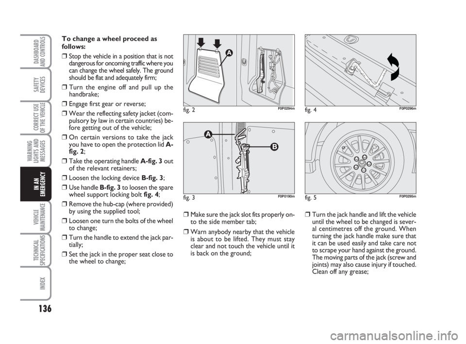
❒On certain versions to take the jack
you have to open the protection lid A-
fig. 2;
❒Take the operating handle A-fig. 3 out
of the relevant retainers;
❒Loosen the locking device B-fig. 3;
❒Use handle B-fig. 3to loosen the spare
wheel support locking bolt fig. 4;
❒Remove the hub-cap (where provided)
by using the supplied tool;
❒Loosen one turn the bolts of the wheel
to change;
❒Turn the handle to extend the jack par-
tially;
❒Set the jack in the proper seat close to
the wheel to change;
❒Make sure the jack slot fits properly on-
to the side member tab;
❒Warn anybody nearby that the vehicle
is about to be lifted. They must stay
clear and not touch the vehicle until it
is back on the ground;
❒Turn the jack handle and lift the vehicle
until the wheel to be changed is sever-
al centimetres off the ground. When
turning the jack handle make sure that
it can be used easily and take care not
to scrape your hand against the ground.
The moving parts of the jack (screw and
joints) may also cause injury if touched.
Clean off any grease;
fig. 4F0P0296m
fig. 5F0P0295m
fig. 2F0P0294m
fig. 3F0P0190m
133-152 Nuovo ScudoG9 GB:133-152 Nuovo ScudoG9 GB 16-11-2009 12:01 Pagina 136
Page 138 of 210
137
WARNING
LIGHTS AND
MESSAGES
VEHICLE
MAINTENANCE
TECHNICAL
SPECIFICATIONS
INDEX
DASHBOARD
AND CONTROLS
SAFETY
DEVICES
CORRECT USE
OF THE
VEHICLE
IN AN
EMERGENCY
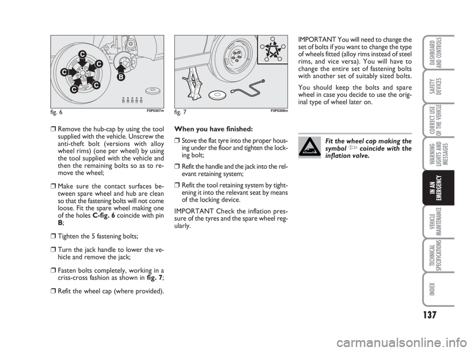
❒Remove the hub-cap by using the tool
supplied with the vehicle. Unscrew the
anti-theft bolt (versions with alloy
wheel rims) (one per wheel) by using
the tool supplied with the vehicle and
then the remaining bolts so as to re-
move the wheel;
❒Make sure the contact surfaces be-
tween spare wheel and hub are clean
so that the fastening bolts will not come
loose. Fit the spare wheel making one
of the holes C-fig. 6coincide with pin
B;
❒Tighten the 5 fastening bolts;
❒Turn the jack handle to lower the ve-
hicle and remove the jack;
❒Fasten bolts completely, working in a
criss-cross fashion as shown in fig. 7;
❒Refit the wheel cap (where provided).When you have finished:
❒Stove the flat tyre into the proper hous-
ing under the floor and tighten the lock-
ing bolt;
❒Refit the handle and the jack into the rel-
evant retaining system;
❒Refit the tool retaining system by tight-
ening it into the relevant seat by means
of the locking device.
IMPORTANT Check the inflation pres-
sure of the tyres and the spare wheel reg-
ularly.IMPORTANT You will need to change the
set of bolts if you want to change the type
of wheels fitted (alloy rims instead of steel
rims, and vice versa). You will have to
change the entire set of fastening bolts
with another set of suitably sized bolts.
You should keep the bolts and spare
wheel in case you decide to use the orig-
inal type of wheel later on.
fig. 6F0P0307mfig. 7F0P0308m
Fit the wheel cap making the
symbol Ycoincide with the
inflation valve.
133-152 Nuovo ScudoG9 GB:133-152 Nuovo ScudoG9 GB 16-11-2009 12:01 Pagina 137
Page 139 of 210

Warning: the gel bottle con-
tains ethylene glycol which is
harmful to your health if swallowed
and irritating for your eyes. Keep
away from children.
WARNING
138
WARNING
LIGHTS AND
MESSAGES
VEHICLE
MAINTENANCE
TECHNICAL
SPECIFICATIONS
INDEX
DASHBOARD
AND CONTROLS
SAFETY
DEVICES
CORRECT USE
OF THE
VEHICLE
IN AN
EMERGENCY
QUICK TYRE REPAIR
KIT FIX & GO
The quick tyre repair kit consists of a
compressor and a bottle (containing seal-
ing fluid).Using the kit
1. Mark the flat tyre on the speed limit-
ing sticker. Stick the label on the steer-
ing wheel as a reminder that the car has
a temporary wheel.
2. Fix the bottle 1on the compressor 2.
3. Connect the bottle 1to the valve of the
tyre to be repaired.
4. Properly unfold the compressor pipe
before connecting it to the bottle.
5. Connect the electric wire to one of the
12 V vehicle sockets.
6. By pushing the button A, operate the
compressor until the tyre pressure
reaches 2.0 bar. If such pressure cannot
be reached, the tyre is irrepairable.
7. Disconnect and store the compressor.
8. Drive at low speed for a few kilometres
to seal the puncture.
9. Use the compressor to adjust the pres-
sure following the recommended pro-
cedure for the vehicle and check that
the puncture is correctly sealed (no
pressure loss).
10. Drive at low speed (80 km/h). The
tyre must be checked and repaired by
a specialist as soon as possible.Once used, the bottle can be stored in the
plastic bag supplied with the kit to prevent
the fluid from staining the vehicle.
Do not dispose of the bottle in the envi-
ronment after use; have it recycled by a
Fiat Dealership or a designated body.
The bottle is available at every Fiat Deal-
ership.
fig. 7bF0P0620m
133-152 Nuovo ScudoG9 GB:133-152 Nuovo ScudoG9 GB 16-11-2009 12:01 Pagina 138
Page 140 of 210
139
WARNING
LIGHTS AND
MESSAGES
VEHICLE
MAINTENANCE
TECHNICAL
SPECIFICATIONS
INDEX
DASHBOARD
AND CONTROLS
SAFETY
DEVICES
CORRECT USE
OF THE
VEHICLE
IN AN
EMERGENCY
WHEN NEEDING TO
CHANGE A BULB
GENERAL INSTRUCTIONS
❒When a light is not working, check that
the corresponding fuse is intact before
changing a bulb. For the location of fus-
es, refer to the paragraph “If a fuse
blows” in this section;
❒ Before changing a bulb check the con-
tacts for oxidation;
❒ Burnt bulbs must be replaced by oth-
ers of the same type and power;
❒ Always check the height of the head-
light beam after changing a bulb.
IMPORTANT The headlight inner surface
may be lightly misted over: this is not a
fault but a natural fact due to low tem-
perature and level of air humidity. It will
disappear as soon the headlights are
turned on. The presence of drops inside
the headlights means water infiltration,
therefore contact Fiat Dealership.
TYPES OF BULBS
Various types of bulbs are fitted to your
vehicle:
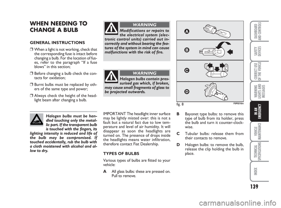
AAll glass bulbs: these are pressed on.
Pull to remove.BBayonet type bulbs: to remove this
type of bulb from its holder, press
the bulb and turn it counter-clock-
wise.
CTubular bulbs: release them from
their contacts to remove.
DHalogen bulbs: to remove the bulb,
release the clip holding the bulb in
place. Halogen bulbs must be han-
dled touching only the metal-
lic part. If the transparent bulb
is touched with the fingers, its
lighting intensity is reduced and life of
the bulb may be compromised. If
touched accidentally, rub the bulb with
a cloth moistened with alcohol and al-
low to dry.
Modifications or repairs to
the electrical system (elec-
tronic control units) carried out in-
correctly and without bearing the fea-
tures of the system in mind can cause
malfunctions with the risk of fire.
WARNING
Halogen bulbs contain pres-
surised gas which, if broken,
may cause small fragments of glass to
be projected outwards.
WARNING
fig. 8F0P0216m
133-152 Nuovo ScudoG9 GB:133-152 Nuovo ScudoG9 GB 16-11-2009 12:01 Pagina 139
Page 141 of 210
140
WARNING
LIGHTS AND
MESSAGES
VEHICLE
MAINTENANCE
TECHNICAL
SPECIFICATIONS
INDEX
DASHBOARD
AND CONTROLS
SAFETY
DEVICES
CORRECT USE
OF THE
VEHICLE
IN AN
EMERGENCY
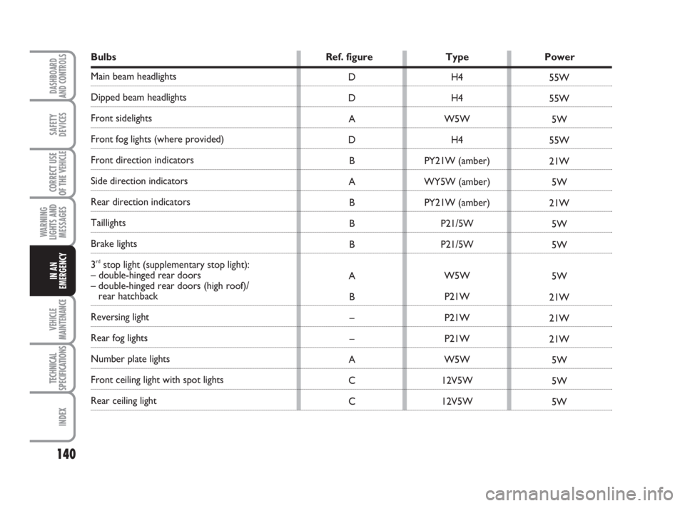
Bulbs Ref. figure Type Power
Main beam headlights
Dipped beam headlights
Front sidelights
Front fog lights (where provided)
Front direction indicators
Side direction indicators
Rear direction indicators
Taillights
Brake lights
3
rdstop light (supplementary stop light):
– double-hinged rear doors
– double-hinged rear doors (high roof)/
rear hatchback
Reversing light
Rear fog lights
Number plate lights
Front ceiling light with spot lights
Rear ceiling lightH4
H4
W5W
H4
PY21W (amber)
WY5W (amber)
PY21W (amber)
P21/5W
P21/5W
W5W
P21W
P21W
P21W
W5W
12V5W
12V5W D
D
A
D
B
A
B
B
B
A
B
–
–
A
C
C55W
55W
5W
55W
21W
5W
21W
5W
5W
5W
21W
21W
21W
5W
5W
5W
133-152 Nuovo ScudoG9 GB:133-152 Nuovo ScudoG9 GB 16-11-2009 12:01 Pagina 140
Page 142 of 210
141
WARNING
LIGHTS AND
MESSAGES
VEHICLE
MAINTENANCE
TECHNICAL
SPECIFICATIONS
INDEX
DASHBOARD
AND CONTROLS
SAFETY
DEVICES
CORRECT USE
OF THE
VEHICLE
IN AN
EMERGENCY
IF AN EXTERIOR BULB
BURNS OUT
For the type of bulb and power rating, see
previous paragraph “If a bulb burns out”.
FRONT LIGHT UNITS
The front light units contain dipped beams,
main beams, sidelights and direction indi-
cators bulbs.DIPPED BEAM/ MAIN BEAM
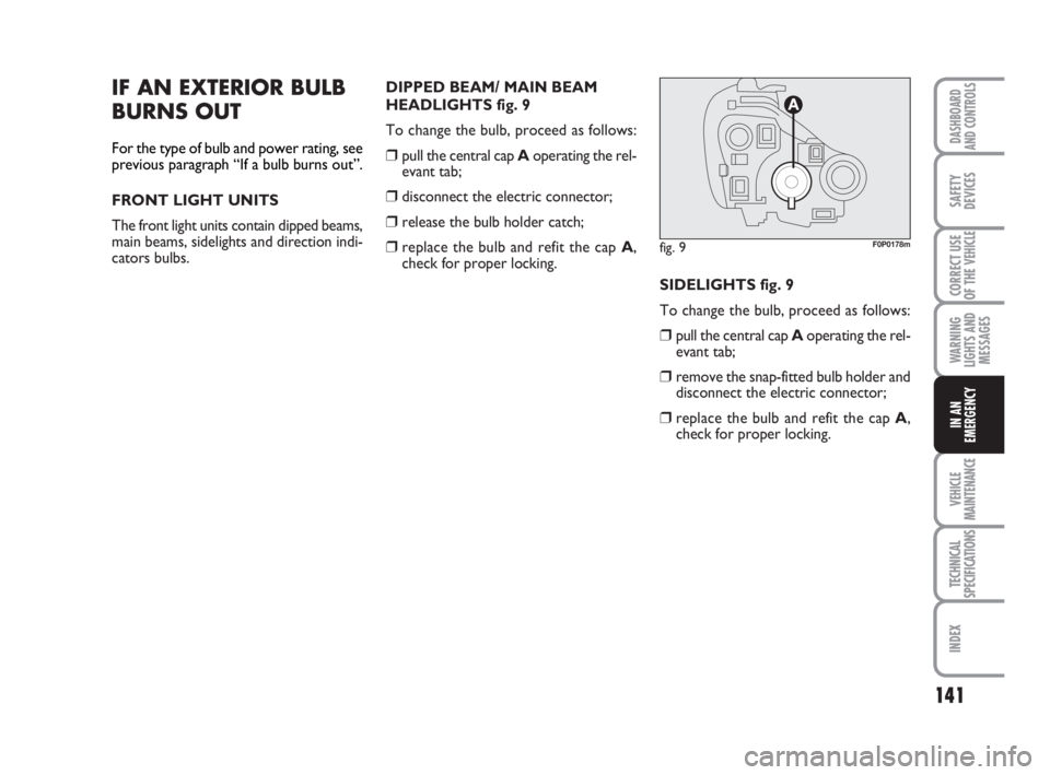
HEADLIGHTS fig. 9
To change the bulb, proceed as follows:
❒pull the central cap Aoperating the rel-
evant tab;
❒disconnect the electric connector;
❒release the bulb holder catch;
❒replace the bulb and refit the cap A,
check for proper locking.
SIDELIGHTS fig. 9
To change the bulb, proceed as follows:
❒pull the central cap Aoperating the rel-
evant tab;
❒remove the snap-fitted bulb holder and
disconnect the electric connector;
❒replace the bulb and refit the cap A,
check for proper locking.
fig. 9F0P0178m
133-152 Nuovo ScudoG9 GB:133-152 Nuovo ScudoG9 GB 16-11-2009 12:01 Pagina 141
Page 143 of 210
142
WARNING
LIGHTS AND
MESSAGES
VEHICLE
MAINTENANCE
TECHNICAL
SPECIFICATIONS
INDEX
DASHBOARD
AND CONTROLS
SAFETY
DEVICES
CORRECT USE
OF THE
VEHICLE
IN AN
EMERGENCY
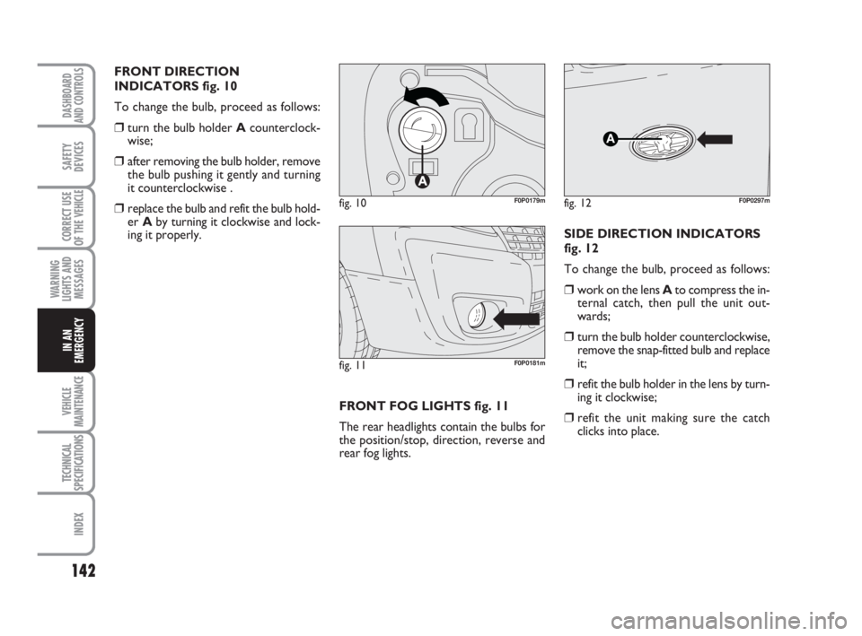
FRONT DIRECTION
INDICATORS fig. 10
To change the bulb, proceed as follows:
❒turn the bulb holder Acounterclock-
wise;
❒after removing the bulb holder, remove
the bulb pushing it gently and turning
it counterclockwise .
❒replace the bulb and refit the bulb hold-
er Aby turning it clockwise and lock-
ing it properly.
FRONT FOG LIGHTS fig. 11
The rear headlights contain the bulbs for
the position/stop, direction, reverse and
rear fog lights.SIDE DIRECTION INDICATORS
fig. 12
To change the bulb, proceed as follows:
❒work on the lens Ato compress the in-
ternal catch, then pull the unit out-
wards;
❒turn the bulb holder counterclockwise,
remove the snap-fitted bulb and replace
it;
❒refit the bulb holder in the lens by turn-
ing it clockwise;
❒refit the unit making sure the catch
clicks into place.
fig. 11F0P0181m
fig. 10F0P0179mfig. 12
A
F0P0297m
133-152 Nuovo ScudoG9 GB:133-152 Nuovo ScudoG9 GB 16-11-2009 12:01 Pagina 142
Page 144 of 210
143
WARNING
LIGHTS AND
MESSAGES
VEHICLE
MAINTENANCE
TECHNICAL
SPECIFICATIONS
INDEX
DASHBOARD
AND CONTROLS
SAFETY
DEVICES
CORRECT USE
OF THE
VEHICLE
IN AN
EMERGENCY
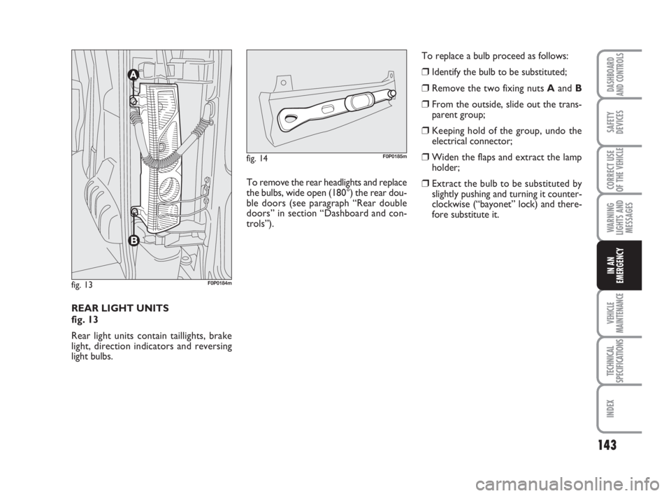
REAR LIGHT UNITS
fig. 13
Rear light units contain taillights, brake
light, direction indicators and reversing
light bulbs.
fig. 13F0P0184m
To remove the rear headlights and replace
the bulbs, wide open (180°) the rear dou-
ble doors (see paragraph “Rear double
doors” in section “Dashboard and con-
trols”).
fig. 14F0P0185m
To replace a bulb proceed as follows:
❒Identify the bulb to be substituted;
❒Remove the two fixing nuts Aand B
❒From the outside, slide out the trans-
parent group;
❒Keeping hold of the group, undo the
electrical connector;
❒Widen the flaps and extract the lamp
holder;
❒Extract the bulb to be substituted by
slightly pushing and turning it counter-
clockwise (“bayonet” lock) and there-
fore substitute it.
133-152 Nuovo ScudoG9 GB:133-152 Nuovo ScudoG9 GB 16-11-2009 12:01 Pagina 143