sensor FIAT SCUDO 2016 Owner handbook (in English)
[x] Cancel search | Manufacturer: FIAT, Model Year: 2016, Model line: SCUDO, Model: FIAT SCUDO 2016Pages: 227, PDF Size: 4.46 MB
Page 8 of 227
4SAFETY
DEVICESCORRECT USE
OF THE VEHICLE
WARNING
LIGHTS AND
MESSAGESIN AN
EMERGENCYVEHICLE
MAINTENANCETECHNICAL
SPECIFICATIONSINDEXDASHBOARD
AND CONTROLS
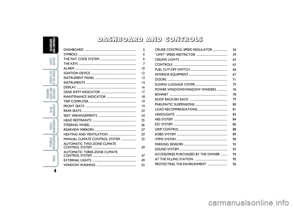
DASHBOARD ...................................................................... 5
SYMBOLS ............................................................................... 6
THE FIAT CODE SYSTEM ................................................. 6
THE KEYS .............................................................................. 7
ALARM ................................................................................... 10
IGNITION DEVICE ............................................................. 12
INSTRUMENT PANEL ........................................................ 13
INSTRUMENTS .................................................................... 14
DISPLAY.................................................................................. 16
GEAR SHITF INDICATOR................................................. 17
MAINTENANCE INDICATOR ........................................ 18
TRIP COMPUTER................................................................. 19
FRONT SEATS ..................................................................... 19
REAR SEATS .......................................................................... 22
SEAT ARRANGEMENTS .................................................... 24
HEAD RESTRAINTS ........................................................... 25
STEERING WHEEL .............................................................. 26
REARVIEW MIRRORS ........................................................ 27
HEATING AND VENTILATION ..................................... 29
MANUAL CLIMATE CONTROL SYSTEM .................... 33
AUTOMATIC TWO-ZONE CLIMATE
CONTROL SYSTEM ........................................................... 39
AUTOMATIC THREE-ZONE CLIMATE
CONTROL SYSTEM ........................................................... 47
EXTERNAL LIGHTS ............................................................ 49
WINDOW WASHING ...................................................... 52CRUISE CONTROL SPEED REGULATOR.................... 56
“LIMIT” SPEED RESTRICTOR .......................................... 59
CEILING LIGHTS ................................................................. 62
CONTROLS .......................................................................... 63
FUEL CUT-OFF SWITCH .................................................. 66
INTERIOR EQUIPMENT..................................................... 67
DOORS .................................................................................. 71
SLIDING LUGGAGE COVER............................................ 75
POWER WINDOWS/WINDOW WINDERS .............. 76
BONNET ............................................................................... 78
ROOF RACK/SKI RACK .................................................... 79
PNEUMATIC SUSPENSIONS............................................. 80
LOAD RECOMMENDATIONS......................................... 81
HEADLIGHTS ....................................................................... 83
ABS SYSTEM ......................................................................... 84
ESC SYSTEM ......................................................................... 86
GRIP CONTROL.................................................................. 88
EOBD SYSTEM ..................................................................... 89
iTPMS SYSTEM....................................................................... 90
PARKING SENSORS ........................................................... 92
SOUND SYSTEM ................................................................. 93
ACCESSORIES PURCHASED BY THE OWNER ......... 94
AT THE FILLING STATION ............................................. 95
PROTECTING THE ENVIRONMENT ........................... 96
D D
A A
S S
H H
B B
O O
A A
R R
D D
A A
N N
D D
C C
O O
N N
T T
R R
O O
L L
S S
001-019 SCUDO LUM GB 27/03/14 10:10 Pagina 4
Page 22 of 227
18SAFETY
DEVICESCORRECT USE
OF THE VEHICLE
WARNING
LIGHTS AND
MESSAGESIN AN
EMERGENCYVEHICLE
MAINTENANCETECHNICAL
SPECIFICATIONSINDEXDASHBOARD
AND CONTROLS
MAINTENANCE
INDICATORIt regulates the intervals between the main-
tenance operations based on vehicle use.
Functioning
As soon as the starting key is inserted and
for a few seconds, the maintenance key lights
up and which indicates the maintenance op-
erations; the total odometer display indicates
the number of kilometres {rounded down}
which can be covered until the next main-
tenance operation. The maintenance expiry
dates are calculated starting from the last re-
setting of the indicator.
This expiry date is determined by means
of two parameters:❒
the distance in kilometres covered
❒
time which has passed since the last
maintenance operation.
The distance in kilometres
which remains to be covered
can be considered by the time
factor, based on the driver’s
driving habits.
F0P0354mF0P0355m
OIL OK
F0P0356m
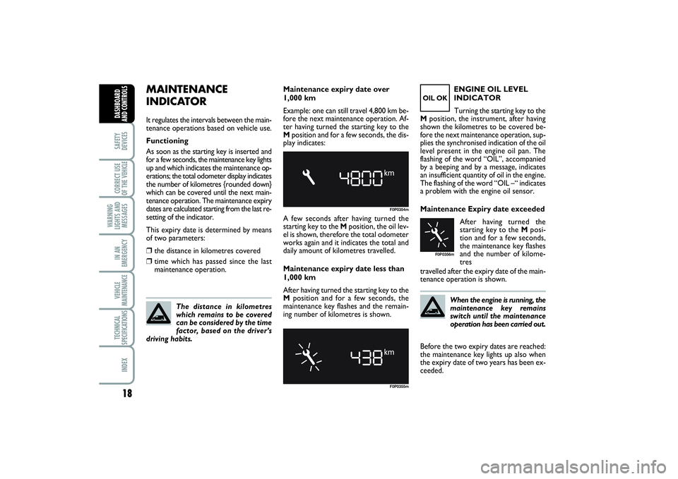
Maintenance expiry date over
1,000 km
Example: one can still travel 4,800 km be-
fore the next maintenance operation. Af-
ter having turned the starting key to the
Mposition and for a few seconds, the dis-
play indicates:
A few seconds after having turned the
starting key to the Mposition, the oil lev-
el is shown, therefore the total odometer
works again and it indicates the total and
daily amount of kilometres travelled.
Maintenance expiry date less than
1,000 km
After having turned the starting key to the
Mposition and for a few seconds, the
maintenance key flashes and the remain-
ing number of kilometres is shown.ENGINE OIL LEVEL
INDICATOR
Turning the starting key to the
Mposition, the instrument, after having
shown the kilometres to be covered be-
fore the next maintenance operation, sup-
plies the synchronised indication of the oil
level present in the engine oil pan. The
flashing of the word “OIL”, accompanied
by a beeping and by a message, indicates
an insufficient quantity of oil in the engine.
The flashing of the word “OIL –“ indicates
a problem with the engine oil sensor.
Maintenance Expiry date exceeded
After having turned the
starting key to the Mposi-
tion and for a few seconds,
the maintenance key flashes
and the number of kilome-
tres
travelled after the expiry date of the main-
tenance operation is shown.
When the engine is running, the
maintenance key remains
switch until the maintenance
operation has been carried out.
Before the two expiry dates are reached:
the maintenance key lights up also when
the expiry date of two years has been ex-
ceeded.
001-019 SCUDO LUM GB 27/03/14 10:10 Pagina 18
Page 55 of 227
51
SAFETY
DEVICESCORRECT USE
OF THE VEHICLE WARNING
LIGHTS AND
MESSAGESIN AN
EMERGENCYVEHICLE
MAINTENANCETECHNICAL
SPECIFICATIONSINDEX DASHBOARD
AND CONTROLS
Follow me home
(for versions/markets, where provided)
This function allows the illumination of the
space in front of the vehicle for a preset
period of time (45 seconds). To activate
it the ignition key shall be at Sor removed
and the left stalk shall be pushed towards
the dashboard within 2 minutes from
when the engine is turned off.
If the vehicle is fitted with automatic de-
vice for turning on side lights and dipped
beams, the follow me home function will
activate automatically when opening the
doors.AUTOMATIC HEADLIGHTS
SENSOR (daylight sensor)
(for versions/markets, where provided)
It detects the changes of the external light
intensity of the vehicle according to the
light sensitivity set: the greater the sensi-
tivity is, the smaller the amount of exter-
nal light necessary to control the switch-
ing-on of the external headlights will be.
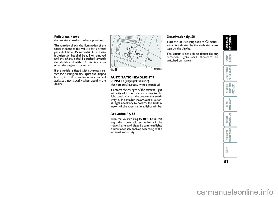
Activation fig. 58
Turn the knurled ring to AUTO: in this
way, the automatic activation of the
side/taillights and dipped beam headlights
is simultaneously enabled according to the
external luminosity.
fig. 58
F0P0286m
Deactivation fig. 58
Turn the knurled ring back to å; deacti-
vation is indicated by the dedicated mes-
sage on the display.
The sensor is not able to detect the fog
presence, lights shall therefore be
switched on manually.
020-082 SCUDO LUM GB 19/11/13 09.54 Pagina 51
Page 57 of 227
53
SAFETY
DEVICESCORRECT USE
OF THE VEHICLE WARNING
LIGHTS AND
MESSAGESIN AN
EMERGENCYVEHICLE
MAINTENANCETECHNICAL
SPECIFICATIONSINDEX DASHBOARD
AND CONTROLS
The rain sensor (fitted on certain versions
only), is an electronic device coupled to
the windscreen wiper with the purpose of
adjusting automatically, during the inter-
mittent operation, the frequency of the
windscreen wiper strokes as to the rain
intensity.
The rain sensor will activate automatical-
ly when moving the stalk to AUTO; its
range varies gradually from windscreen
wiper off (no wipe) when the windscreen
is dry, to wiper at first continuous speed
with heavy rain.
The activation of the rain sensor is sig-
nalled by a control acquisition “stroke”. RAIN SENSOR
(for versions/markets, where provided)
The rain sensor is located behind the dri-
ving mirror in contact with the windscreen
and has the purpose of adjusting auto-
matically, during the intermittent opera-
tion, the frequency of the windscreen
wiper strokes as to the rain intensity.
IMPORTANT Keep clean the glass in the
sensor area.
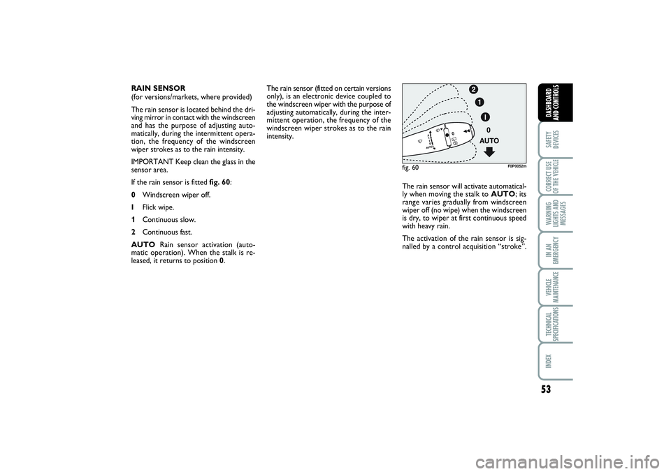
If the rain sensor is fitted fig. 60:
0Windscreen wiper off.
IFlick wipe.
1Continuous slow.
2Continuous fast.
AUTORain sensor activation (auto-
matic operation). When the stalk is re-
leased, it returns to position 0.
fig. 60
F0P0052m
020-082 SCUDO LUM GB 19/11/13 09.54 Pagina 53
Page 58 of 227
54SAFETY
DEVICESCORRECT USE
OF THE VEHICLE
WARNING
LIGHTS AND
MESSAGESIN AN
EMERGENCYVEHICLE
MAINTENANCETECHNICAL
SPECIFICATIONSINDEX
DASHBOARD
AND
CONTROLS
Operating the windscreen washer with
the rain sensor activated the normal wash-
ing cycle is performed at the end of which
the rain sensor resumes its normal auto-
matic function.
So as to deactivate the rain sensor, put the
windscreen wiper command in the I, 1or
2positions. The deactivation is accompa-
nied by a message on the display.
To activate the rain sensor you have to
move the stalk to another position and
then back to AUTO.The rain sensor is able to recognize and
automatically adjust itself in the presence
of the following particular conditions:
❒
impurities on the controlled surface
(salt, dirt, etc...);
❒
streaks of water produced by worn
wiper blades;
❒
difference between day and night (hu-
man eye is more bothered by wet glass
at night).Pulling the stalk towards the steering
wheel (unstable position), regardless of
the position of the knurled ring, operates
the windscreen washer and if the dipped
or high beams are on, also the headlight
washer (for versions/markets, where pro-
vided).
Windscreen wiper will then perform three
wiping strokes.
Do not activate the rain sen-
sor when washing the vehi-
cle at automatic car-wash stations.
WARNING
When cleaning or washing
the windscreen make sure the
rain sensor is off.
WARNING
Do not activate the rain sen-
sor if the windscreen is icy.
WARNING
020-082 SCUDO LUM GB 19/11/13 09.54 Pagina 54
Page 69 of 227
65
SAFETY
DEVICESCORRECT USE
OF THE VEHICLE WARNING
LIGHTS AND
MESSAGESIN AN
EMERGENCYVEHICLE
MAINTENANCETECHNICAL
SPECIFICATIONSINDEX DASHBOARD
AND CONTROLS
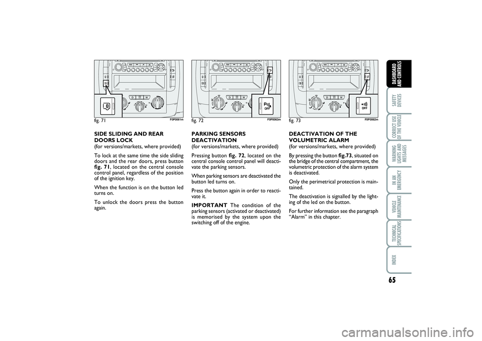
DEACTIVATION OF THE
VOLUMETRIC ALARM
(for versions/markets, where provided)
By pressing the button fig.73, situated on
the bridge of the central compartment, the
volumetric protection of the alarm system
is deactivated.
Only the perimetrical protection is main-
tained.
The deactivation is signalled by the light-
ing of the led on the button.
For further information see the paragraph
“Alarm” in this chapter.
fig. 72
F0P0063m
PARKING SENSORS
DEACTIVATION
(for versions/markets, where provided)
Pressing button fig. 72, located on the
central console control panel will deacti-
vate the parking sensors.
When parking sensors are deactivated the
button led turns on.
Press the button again in order to reacti-
vate it.
IMPORTANTThe condition of the
parking sensors (activated or deactivated)
is memorised by the system upon the
switching off of the engine.
fig. 73
F0P0062m
SIDE SLIDING AND REAR
DOORS LOCK
(for versions/markets, where provided)
To lock at the same time the side sliding
doors and the rear doors, press button
fig. 71, located on the central console
control panel, regardless of the position
of the ignition key.
When the function is on the button led
turns on.
To unlock the doors press the button
again.fig. 71
F0P0061m
020-082 SCUDO LUM GB 19/11/13 09.54 Pagina 65
Page 94 of 227
90SAFETY
DEVICESCORRECT USE
OF THE VEHICLE
WARNING
LIGHTS AND
MESSAGESIN AN
EMERGENCYVEHICLE
MAINTENANCETECHNICAL
SPECIFICATIONSINDEXDASHBOARD
AND CONTROLS
iTPMS SYSTEM(for versions/markets
where provided)
DESCRIPTION
The vehicle can be equipped with the
iTPMS (indirect Tire Pressure Monitor-
ing System) which monitors the tyre in-
flation status thanks to wheel speed sen-
sors.
The system comprises a radio-frequency
transmitter sensor fitted to each wheel
(on the rim inside the tyre), which is able
to send information on the inflation pres-
sure of each tyre to the control unit.
The system warns the driver if one or
more tyres are flat by switching on the
dedicated warning light
n
and a warning
message on the display.
If one tyre only is flat, the system can in-
dicate its position: it is in any case rec-
ommended to check the pressure on all
four tyres.
WARNING
If the system signals a pres-
sure decrease on a specific
tyre, it is recommended to check the
pressure on all four tyres.
WARNING
iTPMS does not relieve the
driver from the obligation to
check the tyre pressure every month;
it is not to be considered a system to
replace maintenance or a safety sys-
tem.
WARNING
Tyre pressure must be
checked with tyres cold.
Should it become necessary for what-
ever reason to check pressure with
warm tyres, do not reduce pressure
even if it is higher than the prescribed
value, but repeat the check when tyres
are cold.
WARNING
The iTPMS cannot indicate
sudden tyre pressure drops
(for example when a tyre bursts). In
this event, brake the vehicle cautious-
ly and avoid sudden steering.
WARNING
The system only warns that
the tyre pressure is low: it is
not able to inflate them.
WARNING
Insufficient tyre inflation in-
creases fuel consumption, re-
duces the tread duration and may af-
fect the capacity to drive safely.
083-096 SCUDO LUM GB 27/03/14 10:22 Pagina 90
Page 95 of 227
91
SAFETY
DEVICESCORRECT USE
OF THE VEHICLE WARNING
LIGHTS AND
MESSAGESIN AN
EMERGENCYVEHICLE
MAINTENANCETECHNICAL
SPECIFICATIONSINDEX DASHBOARD
AND CONTROLS
Insufficient tyre pressure
The warning light
n
switches on, to-
gether with a dedicated message on the
display, to indicate that the tyre pressure
is lower than the recommended value
and/or that slow pressure loss is occur-
ring. In these circumstances, optimal tyre
duration and fuel consumption may not be
guaranteed.
Should two or more tyres be in the con-
dition mentioned above, the display will
show the indications corresponding to each
tyre in sequence.
❒
Slow down immediately, avoid sudden
braking and steering.
❒
Stop as soon as traffic conditions al-
low.
❒
In the event of a puncture, use the
quick tyre repair kit or fit the spare
wheel (for versions/markets, where
provided);
or
❒
if you have a compressor, for example
the one of the quick tyre repair kit,
check the pressure of the four tyres
when cold;or
❒
if you cannot check the pressure im-
mediately, drive very carefully and slow-
ly.
The alarm is active until the next inflation,
repair or replacement of the tyre involved.
The spare wheel (space-saver wheel or
steel rim) does not have sensors.
The detected pressure loss does not al-
ways involve visible deformation of the
tyre. Therefore, do not rely on the visual
check only.iTPMS failure
When a fault in the iT.P.M.S. is detected,
the warning light
n
switches on and flash-
es, the warning light è
switches on as
well and a dedicated message is displayed.
In this case, the monitoring of the tyre
pressure is no longer guaranteed.
This alarm is displayed also when at least
one of the wheels is not equipped with
sensor (e.g. with spare wheel, space-saver
or steel type).
Contact a Fiat Dealership to have the sys-
tem checked or, after a puncture, refit a
tyre equipped with sensor on the origi-
nal rim.
083-096 SCUDO LUM GB 27/03/14 10:22 Pagina 91
Page 96 of 227
92SAFETY
DEVICESCORRECT USE
OF THE VEHICLE
WARNING
LIGHTS AND
MESSAGESIN AN
EMERGENCYVEHICLE
MAINTENANCETECHNICAL
SPECIFICATIONSINDEXDASHBOARD
AND CONTROLS
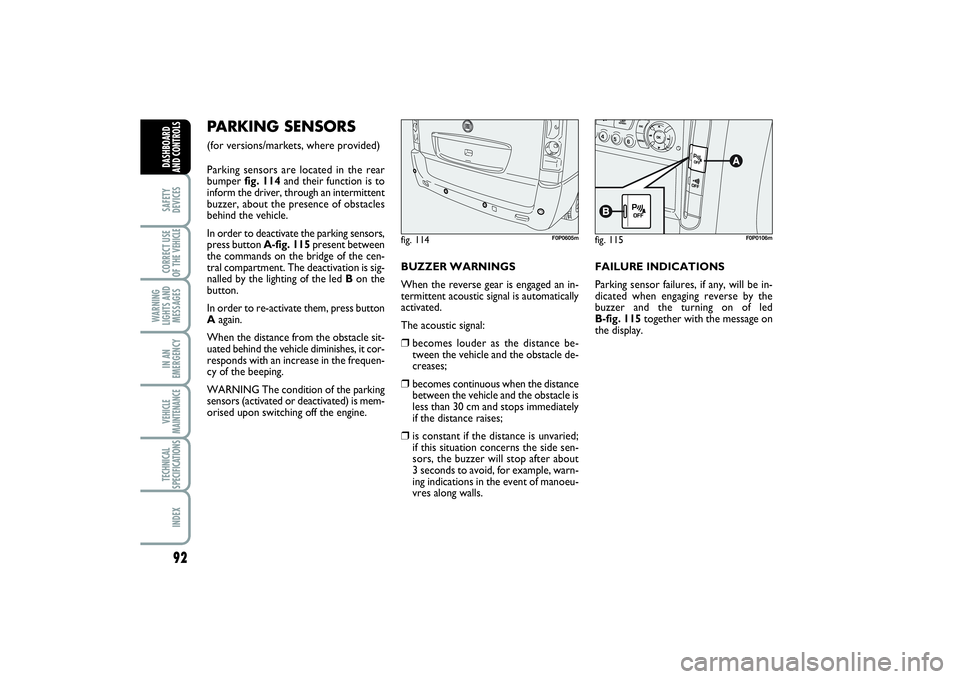
PARKING SENSORS (for versions/markets, where provided)
Parking sensors are located in the rear
bumper fig. 114and their function is to
inform the driver, through an intermittent
buzzer, about the presence of obstacles
behind the vehicle.
In order to deactivate the parking sensors,
press button A-fig. 115present between
the commands on the bridge of the cen-
tral compartment. The deactivation is sig-
nalled by the lighting of the led Bon the
button.
In order to re-activate them, press button
Aagain.
When the distance from the obstacle sit-
uated behind the vehicle diminishes, it cor-
responds with an increase in the frequen-
cy of the beeping.
WARNING The condition of the parking
sensors (activated or deactivated) is mem-
orised upon switching off the engine.BUZZER WARNINGS
When the reverse gear is engaged an in-
termittent acoustic signal is automatically
activated.
The acoustic signal:
❒
becomes louder as the distance be-
tween the vehicle and the obstacle de-
creases;
❒
becomes continuous when the distance
between the vehicle and the obstacle is
less than 30 cm and stops immediately
if the distance raises;
❒
is constant if the distance is unvaried;
if this situation concerns the side sen-
sors, the buzzer will stop after about
3 seconds to avoid, for example, warn-
ing indications in the event of manoeu-
vres along walls.FAILURE INDICATIONS
Parking sensor failures, if any, will be in-
dicated when engaging reverse by the
buzzer and the turning on of led
B-fig. 115together with the message on
the display.
fig. 114
F0P0605m
fig. 115
F0P0106m
083-096 SCUDO LUM GB 27/03/14 10:22 Pagina 92
Page 97 of 227
93
SAFETY
DEVICESCORRECT USE
OF THE VEHICLE WARNING
LIGHTS AND
MESSAGESIN AN
EMERGENCYVEHICLE
MAINTENANCETECHNICAL
SPECIFICATIONSINDEX DASHBOARD
AND CONTROLS
GENERAL WARNINGS❒
When parking, take the utmost care to
obstacles that may be set above or un-
der the sensors.
❒
Objects set close to the vehicle, under
certain circumstances are not detected
and could therefore cause damages to
the vehicle or be damaged.
❒
Indications sent by the sensors can be
altered by dirt, snow or ice deposited
on the sensors or by ultrasound sys-
tems (e.g.: truck pneumatic brakes or
pneumatic hammers) set nearby the ve-
hicle. For proper operation, the
parking sensors shall always
be clean from mud, dirt, snow
or ice. When cleaning the sen-
sors, take the utmost care to prevent
their damaging; do not use therefore
dry or rough clothes. Sensors shall be
washed with clean water and vehicle
detergent, if required.
Parking manoeuvres howev-
er are always under the dri-
ver’s responsibility that shall always
check the absence of people (spe-
cially children) or animals in the ma-
noeuvre space. This system is just a
help for the driver but she/he shall
never reduce attention during dan-
gerous manoeuvres even if performed
at low speed.
WARNING
OPERATION WITH TRAILER
Deactivate parking sensors if you use the
vehicle with trailer.
SOUND SYSTEM(for versions/markets, where provided)
For the operation of the radio with
CD/MP3 CD player (for versions/markets,
where provided), read the instructions for
use given in the Supplement attached to
this Owner Handbook.
SOUND SYSTEM PRESETTING
(for versions/markets, where provided)
For details about the radio installed on the
vehicle and the relevant system, read the
instructions for use given in Supplement
“Sound System” attached to this Owner
Handbook.
For connection to existing
vehicle presetting system,
contact Fiat Dealership to prevent
any trouble that could impair vehicle
safety.
WARNING
083-096 SCUDO LUM GB 27/03/14 10:22 Pagina 93