technical specifications FIAT STILO 2006 1.G Repair Manual
[x] Cancel search | Manufacturer: FIAT, Model Year: 2006, Model line: STILO, Model: FIAT STILO 2006 1.GPages: 274, PDF Size: 4.76 MB
Page 65 of 274
64
SAFETY
DEVICES
CORRECT USE
OF THE CAR
WARNING
LIGHTS AND
MESSAGES
IN AN
EMERGENCY
CAR
MAINTENANCE
TECHNICAL
SPECIFICATIONS
INDEX
DASHBOARD
AND CONTROLS
DEVICE ENGAGEMENT
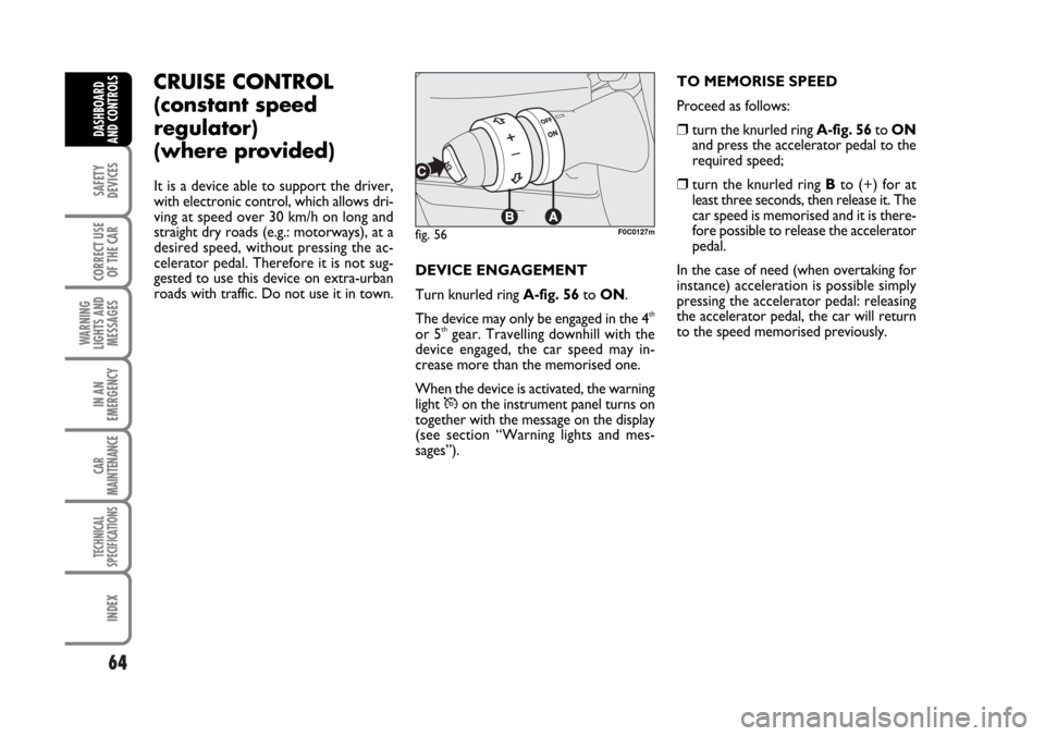
Turn knurled ring A-fig. 56to ON.
The device may only be engaged in the 4
th
or 5thgear. Travelling downhill with the
device engaged, the car speed may in-
crease more than the memorised one.
When the device is activated, the warning
light
Üon the instrument panel turns on
together with the message on the display
(see section “Warning lights and mes-
sages”).TO MEMORISE SPEED
Proceed as follows:
❒turn the knurled ring A-fig. 56to ON
and press the accelerator pedal to the
required speed;
❒turn the knurled ring Bto (+) for at
least three seconds, then release it. The
car speed is memorised and it is there-
fore possible to release the accelerator
pedal.
In the case of need (when overtaking for
instance) acceleration is possible simply
pressing the accelerator pedal: releasing
the accelerator pedal, the car will return
to the speed memorised previously.
fig. 56F0C0127m
CRUISE CONTROL
(constant speed
regulator)
(where provided)
It is a device able to support the driver,
with electronic control, which allows dri-
ving at speed over 30 km/h on long and
straight dry roads (e.g.: motorways), at a
desired speed, without pressing the ac-
celerator pedal. Therefore it is not sug-
gested to use this device on extra-urban
roads with traffic. Do not use it in town.
Page 66 of 274

65
SAFETY
DEVICES
CORRECT USE
OF THE CAR
WARNING
LIGHTS AND
MESSAGES
IN AN
EMERGENCY
CAR
MAINTENANCE
TECHNICAL
SPECIFICATIONS
INDEX
DASHBOARD
AND CONTROLS
TO RESET THE MEMORISED
SPEED
If the device has been disengaged for ex-
ample pressing the brake or clutch pedal,
the memorised speed can be reset as fol-
lows:
❒accelerate gradually until reaching a
speed approaching the one memorised;
❒engage the gear selected at the time of
speed memorising (4thor 5thgear);
❒press button C-fig. 56.TO REDUCE MEMORISED SPEED
The speed memorised can be increased in
two ways:
❒ disengaging the device and then mem-
orising the new speed;
or
❒keeping the knurled ring B-fig. 56to
(–) until reaching the new speed which
will be memorised automatically.
Each turn of the knurled ring will corre-
spond to a slight reduction in speed (about
1 km/h), while keeping the knurled ring
turned will correspond to a continuous
speed reduction. TO INCREASE THE MEMORISED
SPEED
The speed memorised can be increased in
two ways:
❒ pressing the accelerator and then mem-
orising the new speed reached;
or
❒turning the knurled ring B-fig. 56tem-
porarily to (+).
Each turn of the knurled ring will corre-
spond to a slight increase in speed (about
1 km/h), while keeping the knurled ring
turned will correspond to a continuous
speed increase.
Page 67 of 274
66
SAFETY
DEVICES
CORRECT USE
OF THE CAR
WARNING
LIGHTS AND
MESSAGES
IN AN
EMERGENCY
CAR
MAINTENANCE
TECHNICAL
SPECIFICATIONS
INDEX
DASHBOARD
AND CONTROLS
DEVICE DISENGAGEMENT
Turn the knurled ring A-fig. 56to OFF
or the ignition key to STOP. The device
is automatically deactivated also in one of
the following cases:
❒pressing the brake or clutch pedal;
❒ASR or ESP cut-in (where provided);
❒gearshifting in versions with Selespeed
automatic transmission (where provid-
ed);
❒involuntarily moving the Selespeed
lever (where provided) toN.
When travelling with the de-
vice on, never set the
gearshift lever to neutral and do not
move the Selespeed lever to N.
WARNING
In the event of device mal-
function or failure, turn the
knurled ring A-fig. 56to OFF and
contact a Fiat Dealership after check-
ing the protection fuse integrity.
WARNING
Page 68 of 274
67
SAFETY
DEVICES
CORRECT USE
OF THE CAR
WARNING
LIGHTS AND
MESSAGES
IN AN
EMERGENCY
CAR
MAINTENANCE
TECHNICAL
SPECIFICATIONS
INDEX
DASHBOARD
AND CONTROLS
CEILING LIGHTS
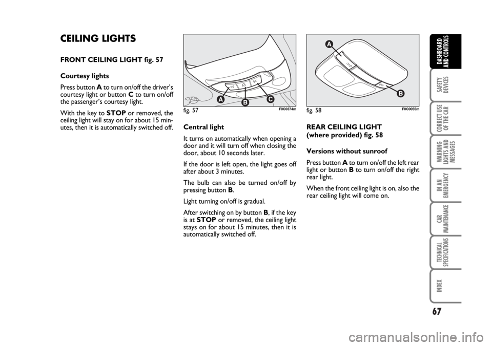
FRONT CEILING LIGHT fig. 57
Courtesy lights
Press button Ato turn on/off the driver’s
courtesy light or button Cto turn on/off
the passenger’s courtesy light.
With the key to STOPor removed, the
ceiling light will stay on for about 15 min-
utes, then it is automatically switched off.Central light
It turns on automatically when opening a
door and it will turn off when closing the
door, about 10 seconds later.
If the door is left open, the light goes off
after about 3 minutes.
The bulb can also be turned on/off by
pressing button B.
Light turning on/off is gradual.
After switching on by button B, if the key
is at STOPor removed, the ceiling light
stays on for about 15 minutes, then it is
automatically switched off.REAR CEILING LIGHT
(where provided) fig. 58
Versions without sunroof
Press button Ato turn on/off the left rear
light or button Bto turn on/off the right
rear light.
When the front ceiling light is on, also the
rear ceiling light will come on.
fig. 57F0C0374mfig. 58F0C0055m
Page 69 of 274
68
SAFETY
DEVICES
CORRECT USE
OF THE CAR
WARNING
LIGHTS AND
MESSAGES
IN AN
EMERGENCY
CAR
MAINTENANCE
TECHNICAL
SPECIFICATIONS
INDEX
DASHBOARD
AND CONTROLS
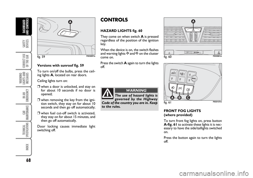
Versions with sunroof fig. 59
To turn on/off the bulbs, press the ceil-
ing lights A, located on rear doors.
Ceiling lights turn on:
❒when a door is unlocked, and stay on
for about 10 seconds if no door is
opened;
❒when removing the key from the igni-
tion switch, they stay on for about 10
seconds and then go off automatically;
❒when fuel cut-off switch is activated,
they stay on for about 15 minutes, and
then go off automatically.
Door locking causes immediate light
switching off.
CONTROLS
HAZARD LIGHTS fig. 60
They come on when switch Ais pressed
regardless of the position of the ignition
key.
When the device is on, the switch flashes
and warning lights
Îand ¥on the cluster
come on.
Press the switch Aagain to turn the lights
off.
FRONT FOG LIGHTS
(where provided)
To turn front fog lights on, press button
A-fig. 61to activate these lights it is nec-
essary to have the side/taillights switched
on.
Press the button again to turn the lights
off. fig. 59F0C0297mfig. 60F0C0081m
fig. 61F0C0137m
The use of hazard lights is
governed by the Highway
Code of the country you are in. Keep
to the rules.
WARNING
Page 70 of 274
69
SAFETY
DEVICES
CORRECT USE
OF THE CAR
WARNING
LIGHTS AND
MESSAGES
IN AN
EMERGENCY
CAR
MAINTENANCE
TECHNICAL
SPECIFICATIONS
INDEX
DASHBOARD
AND CONTROLS
PARKING LIGHTS
These lights can only be turned on with ig-
nition key at STOPor removed, by
pressing button B-fig. 61for about 1 sec-
ond.
Press the button again to turn the light off.
REAR FOG LIGHTS
To turn rear fog lights on, press button C-
fig. 61, to activate these lights it is nec-
essary to have the dipped beams or front
fog lights switched on.
Press the button again to turn the lights
off. Carefully inspect the car to find fuel leaks,
e.g. in the engine compartment, under the
car or near the tank.
If no fuel leaks are found and the car can
be started again, press button Ato reset
the fuel system and the lights.
After a crash, remember to turn the igni-
tion key to STOPto prevent battery run-
down.
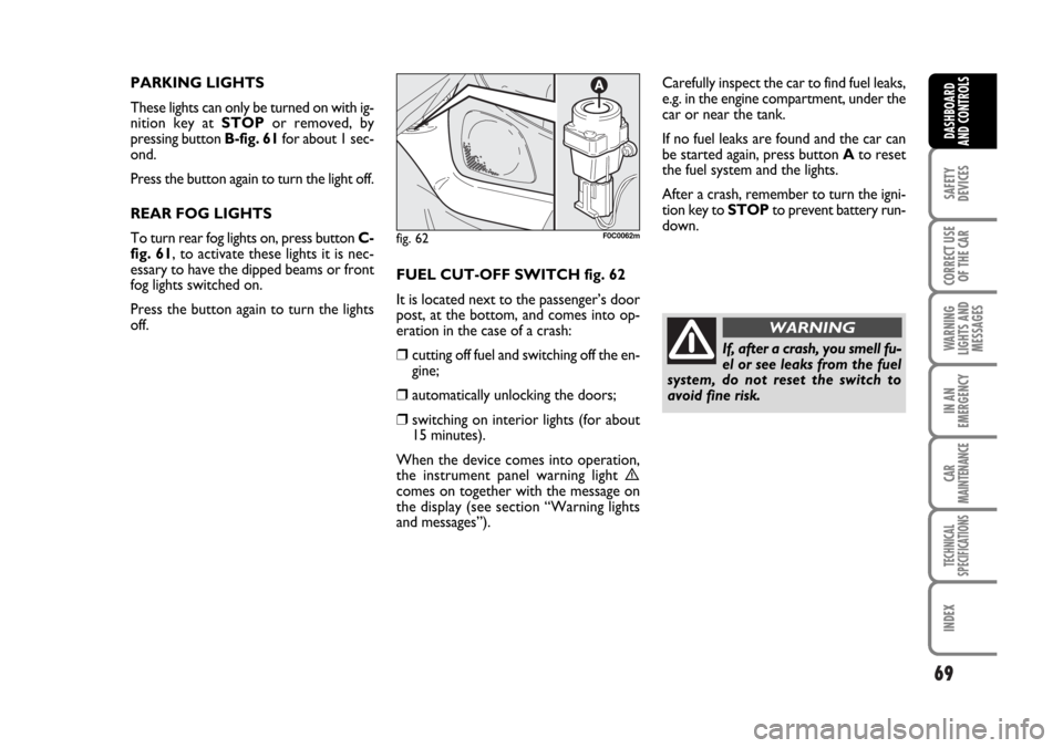
FUEL CUT-OFF SWITCH fig. 62
It is located next to the passenger’s door
post, at the bottom, and comes into op-
eration in the case of a crash:
❒cutting off fuel and switching off the en-
gine;
❒automatically unlocking the doors;
❒switching on interior lights (for about
15 minutes).
When the device comes into operation,
the instrument panel warning light
ècomes on together with the message on
the display (see section “Warning lights
and messages”).
fig. 62F0C0062m
If, after a crash, you smell fu-
el or see leaks from the fuel
system, do not reset the switch to
avoid fine risk.
WARNING
Page 71 of 274
70
SAFETY
DEVICES
CORRECT USE
OF THE CAR
WARNING
LIGHTS AND
MESSAGES
IN AN
EMERGENCY
CAR
MAINTENANCE
TECHNICAL
SPECIFICATIONS
INDEX
DASHBOARD
AND CONTROLS
INTERIOR FITTINGS
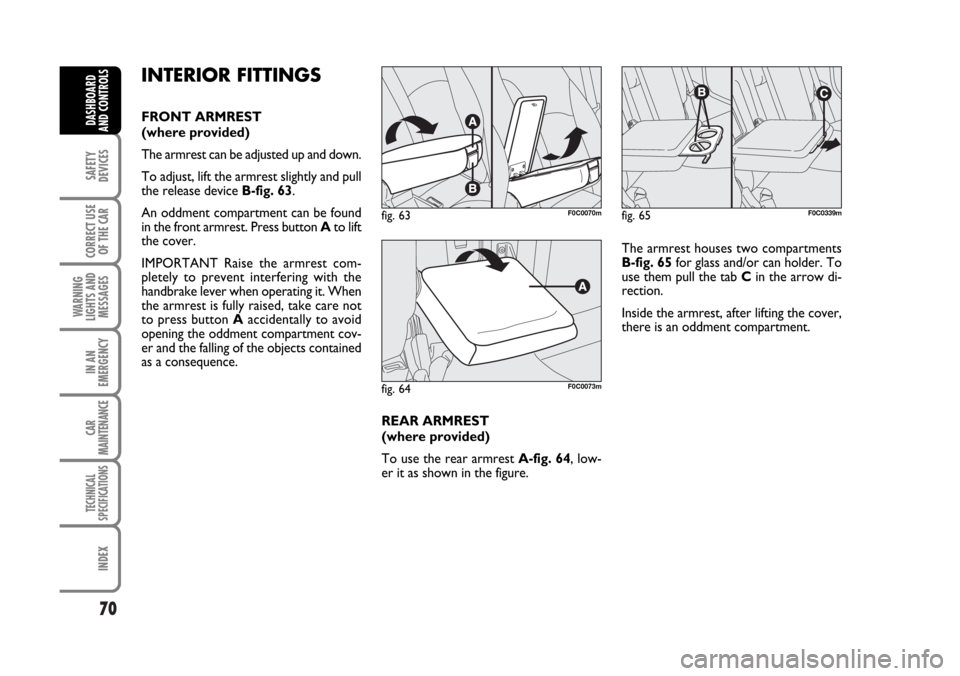
FRONT ARMREST
(where provided)
The armrest can be adjusted up and down.
To adjust, lift the armrest slightly and pull
the release device B-fig. 63.
An oddment compartment can be found
in the front armrest. Press button Ato lift
the cover.
IMPORTANT Raise the armrest com-
pletely to prevent interfering with the
handbrake lever when operating it. When
the armrest is fully raised, take care not
to press button Aaccidentally to avoid
opening the oddment compartment cov-
er and the falling of the objects contained
as a consequence.
REAR ARMREST
(where provided)
To use the rear armrest A-fig. 64, low-
er it as shown in the figure.The armrest houses two compartments
B-fig. 65for glass and/or can holder. To
use them pull the tab Cin the arrow di-
rection.
Inside the armrest, after lifting the cover,
there is an oddment compartment.
fig. 63F0C0070m
fig. 64F0C0073m
fig. 65F0C0339m
Page 72 of 274
71
SAFETY
DEVICES
CORRECT USE
OF THE CAR
WARNING
LIGHTS AND
MESSAGES
IN AN
EMERGENCY
CAR
MAINTENANCE
TECHNICAL
SPECIFICATIONS
INDEX
DASHBOARD
AND CONTROLS
ODDMENT COMPARTMENTS
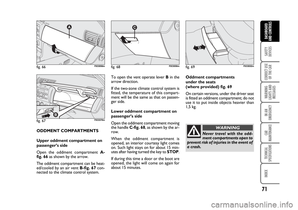
Upper oddment compartment on
passenger’s side
Open the oddment compartment A-
fig. 66as shown by the arrow.
The oddment compartment can be heat-
ed/cooled by an air vent B-fig. 67con-
nected to the climate control system.To open the vent operate lever Bin the
arrow direction.
If the two-zone climate control system is
fitted, the temperature of this compart-
ment will be the same as that on passen-
ger side.
Lower oddment compartment on
passenger’s side
Open the oddment compartment moving
the handle C-fig. 68, as shown by the ar-
row.
When the oddment compartment is
opened, an interior courtesy light comes
on. Such light stays on for about 15 min-
utes after having turned the key to STOP.
If during this time a door or the boot are
opened, the light will come on again for
about 15 minutes.Oddment compartments
under the seats
(where provided) fig. 69
On certain versions, under the driver seat
is fitted an oddment compartment; do not
use it to put inside objects heavier than
1,5 kg.
fig. 66F0C0058m
fig. 67F0C0376m
fig. 68F0C0056mfig. 69F0C0032m
Never travel with the odd-
ment compartments open to
prevent risk of injuries in the event of
a crash.
WARNING
Page 73 of 274
72
SAFETY
DEVICES
CORRECT USE
OF THE CAR
WARNING
LIGHTS AND
MESSAGES
IN AN
EMERGENCY
CAR
MAINTENANCE
TECHNICAL
SPECIFICATIONS
INDEX
DASHBOARD
AND CONTROLS
CURRENT OUTLET (12V)
The current outlet is located on the cen-
tral console and it only works with igni-
tion key at MAR. If the smokers’ kit is re-
quested, the current outlet will be re-
placed by the cigar lighter (see next para-
graph).
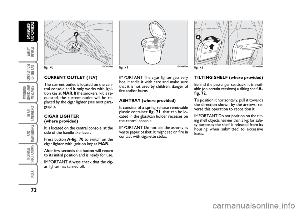
CIGAR LIGHTER
(where provided)
It is located on the central console, at the
side of the handbrake lever.
Press button A-fig. 70to switch on the
cigar lighter with ignition key at MAR.
After few seconds the button will return
to its initial position and is ready for use.
IMPORTANT Always check that the cig-
ar lighter has turned off.IMPORTANT The cigar lighter gets very
hot. Handle it with care and make sure
that it is not used by children: danger of
fire and/or burns.
ASHTRAY (where provided)
It consists of a spring-release removable
plastic container fig. 71, that can be lo-
cated in the glass/can holder recesses on
the central console.
IMPORTANT Do not use the ashtray as
waste paper basket: it might set on fire in
contact with cigarette stubs.TILTING SHELF (where provided)
Behind the passenger seatback, it is avail-
able (on certain versions) a tilting shelf A-
fig. 72.
To position it horizontally, pull it towards
the direction shown by the arrows; re-
verse this operation to reposition it.
IMPORTANT Do not position on the tilt-
ing shelf objects heavier than 3 kg: for safe-
ty purposes the shelf is released from its
housing when submitted to excessive
loads.
fig. 70F0C0102mfig. 71F0C0475mfig. 72F0C0076m
Page 74 of 274
73
SAFETY
DEVICES
CORRECT USE
OF THE CAR
WARNING
LIGHTS AND
MESSAGES
IN AN
EMERGENCY
CAR
MAINTENANCE
TECHNICAL
SPECIFICATIONS
INDEX
DASHBOARD
AND CONTROLS
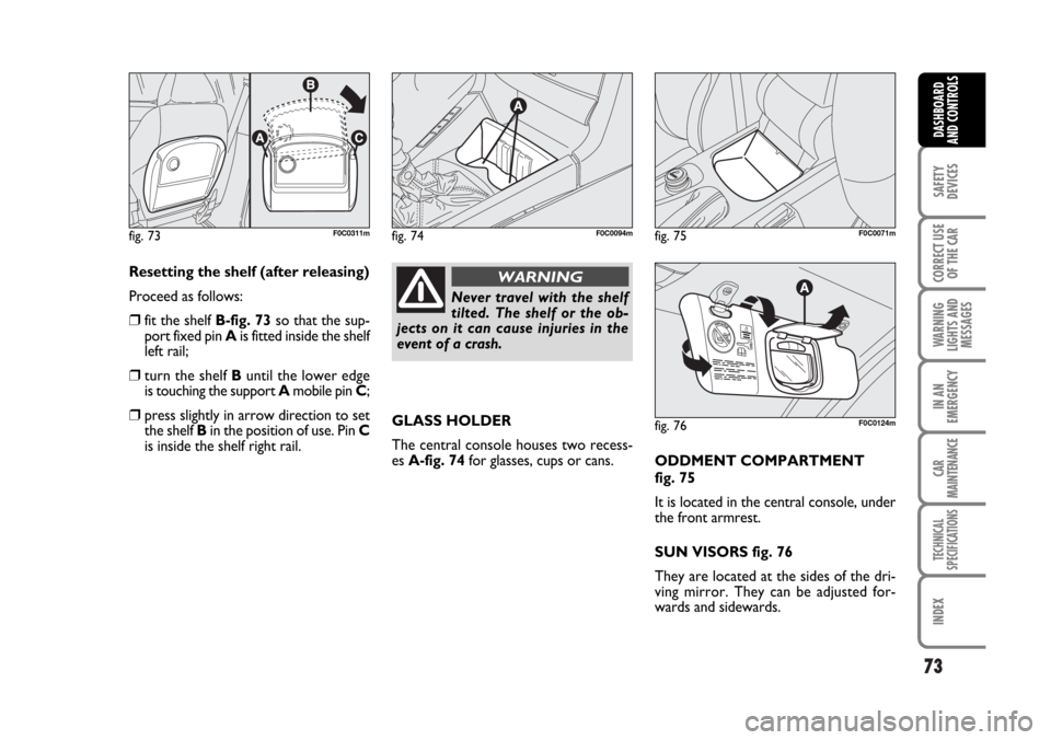
Resetting the shelf (after releasing)
Proceed as follows:
❒fit the shelf B-fig. 73so that the sup-
port fixed pin Ais fitted inside the shelf
left rail;
❒turn the shelf Buntil the lower edge
is touching the support Amobile pin C;
❒press slightly in arrow direction to set
the shelf Bin the position of use. Pin C
is inside the shelf right rail.GLASS HOLDER
The central console houses two recess-
es A-fig. 74for glasses, cups or cans.
ODDMENT COMPARTMENT
fig. 75
It is located in the central console, under
the front armrest.
SUN VISORS fig. 76
They are located at the sides of the dri-
ving mirror. They can be adjusted for-
wards and sidewards.
fig. 73F0C0311m
Never travel with the shelf
tilted. The shelf or the ob-
jects on it can cause injuries in the
event of a crash.
WARNING
fig. 74F0C0094mfig. 75F0C0071m
fig. 76F0C0124m