max FIAT ULYSSE 2008 2.G Owners Manual
[x] Cancel search | Manufacturer: FIAT, Model Year: 2008, Model line: ULYSSE, Model: FIAT ULYSSE 2008 2.GPages: 254, PDF Size: 3.46 MB
Page 2 of 254
Dear Customer,
Thank you for selecting Fiat and congratulations on your choice of a Ulysse.
We have written this booklet to help you get to know all your new Ulysse’s features and use it in the best possi-
ble way.
You should read it right through before taking to the road for the first time.
You will find information, tips and important warnings regarding the driving of the vehicle to help you derive the
maximum from your Ulysse’s technological features. You will also find very valuable tips for your own safety, the
car’s weelbeing and about how to protect the environment.
The Warranty Booklet lists the services that Fiat offers its Customers:
• the Warranty Certificate, with terms and conditions for maintaining its validity
• the range of additional services available to Fiat Customers.
Best regards and good motoring!
1
This Owner Handbook describes all the Fiat Ulysse versions. As a consequence, you should consider
only the information which is related to the engine and bodywork version of the car you purchased.
Page 8 of 254
7
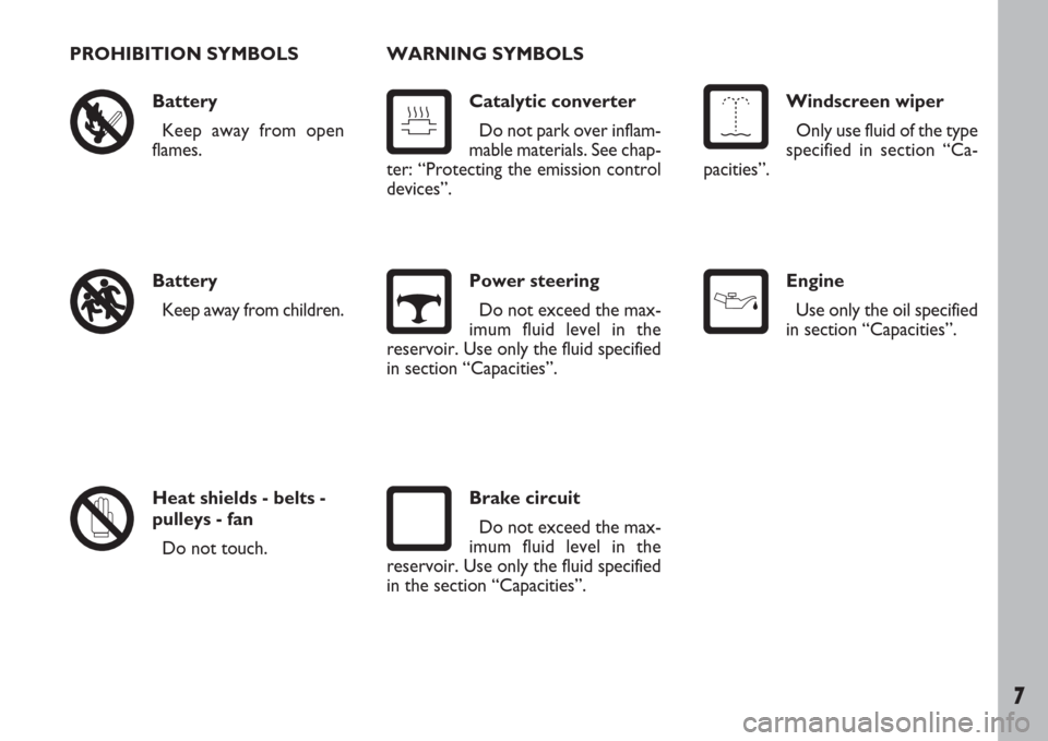
PROHIBITION SYMBOLS
Battery
Keep away from open
flames.
Battery
Keep away from children.
Heat shields - belts -
pulleys - fan
Do not touch.WARNING SYMBOLS
Catalytic converter
Do not park over inflam-
mable materials. See chap-
ter: “Protecting the emission control
devices”.
Power steering
Do not exceed the max-
imum fluid level in the
reservoir. Use only the fluid specified
in section “Capacities”.
Brake circuit
Do not exceed the max-
imum fluid level in the
reservoir. Use only the fluid specified
in the section “Capacities”.
Windscreen wiper
Only use fluid of the type
specified in section “Ca-
pacities”.
Engine
Use only the oil specified
in section “Capacities”.
Page 21 of 254
GETTING TO KNOW YOUR CAR
20
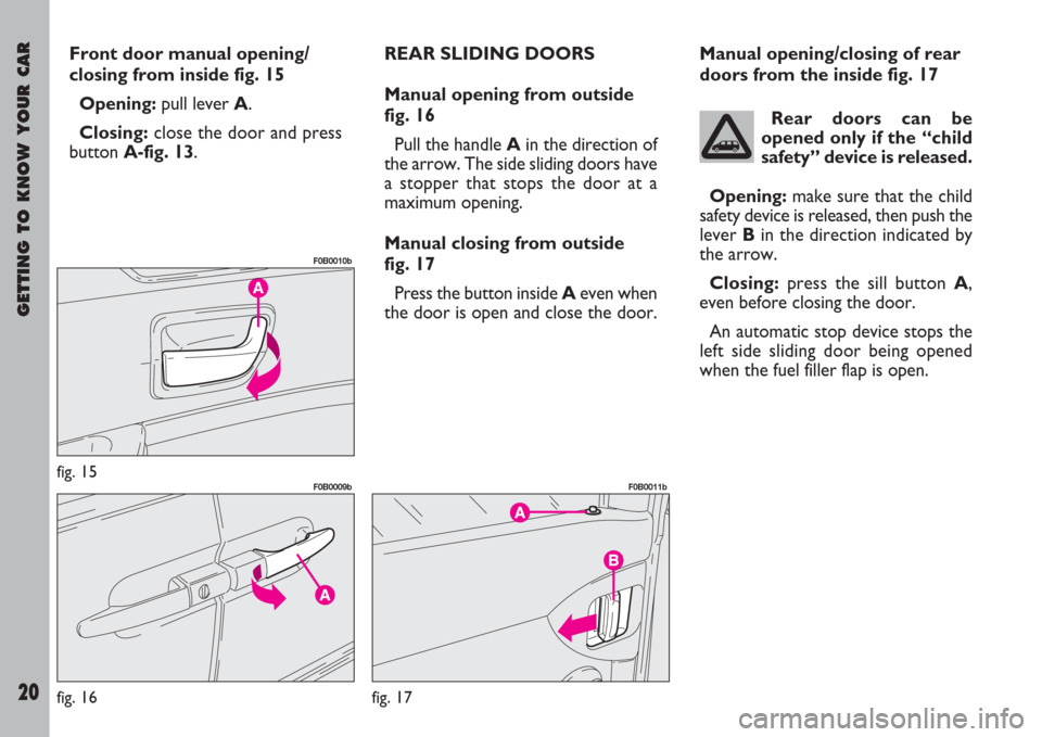
Front door manual opening/
closing from inside fig. 15
Opening:pull lever A.
Closing:close the door and press
buttonA-fig. 13.REAR SLIDING DOORS
Manual opening from outside
fig. 16
Pull the handle Ain the direction of
the arrow. The side sliding doors have
a stopper that stops the door at a
maximum opening.
Manual closing from outside
fig. 17
Press the button inside Aeven when
the door is open and close the door.Manual opening/closing of rear
doors from the inside fig. 17
Rear doors can be
opened only if the “child
safety” device is released.
Opening:make sure that the child
safety device is released, then push the
lever Bin the direction indicated by
the arrow.
Closing:press the sill button A,
even before closing the door.
An automatic stop device stops the
left side sliding door being opened
when the fuel filler flap is open.
fig. 15
F0B0010b
fig. 16
F0B0009b
fig. 17
F0B0011b
Page 26 of 254
GETTING TO KNOW YOUR CAR
25
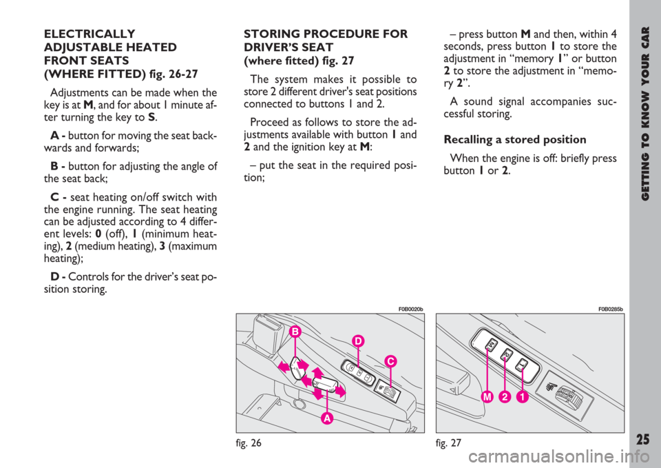
ELECTRICALLY
ADJUSTABLE HEATED
FRONT SEATS
(WHERE FITTED) fig. 26-27
Adjustments can be made when the
key is at M, and for about 1 minute af-
ter turning the key to S.
A -button for moving the seat back-
wards and forwards;
B -button for adjusting the angle of
the seat back;
C -seat heating on/off switch with
the engine running. The seat heating
can be adjusted according to 4 differ-
ent levels: 0(off), 1(minimum heat-
ing), 2(medium heating), 3(maximum
heating);
D -Controls for the driver’s seat po-
sition storing. STORING PROCEDURE FOR
DRIVER’S SEAT
(where fitted) fig. 27
The system makes it possible to
store 2 different driver's seat positions
connected to buttons 1 and 2.
Proceed as follows to store the ad-
justments available with button 1and
2and the ignition key at M:
– put the seat in the required posi-
tion;– press button Mand then, within 4
seconds, press button 1to store the
adjustment in “memory 1” or button
2to store the adjustment in “memo-
ry 2”.
A sound signal accompanies suc-
cessful storing.
Recalling a stored position
When the engine is off: briefly press
button 1or 2.
fig. 26
F0B0020b
fig. 27
F0B0285b
Page 34 of 254
GETTING TO KNOW YOUR CAR
33
fig. 48
F0B0227b
fig. 49
F0B0024b
fig. 50
F0B0017b
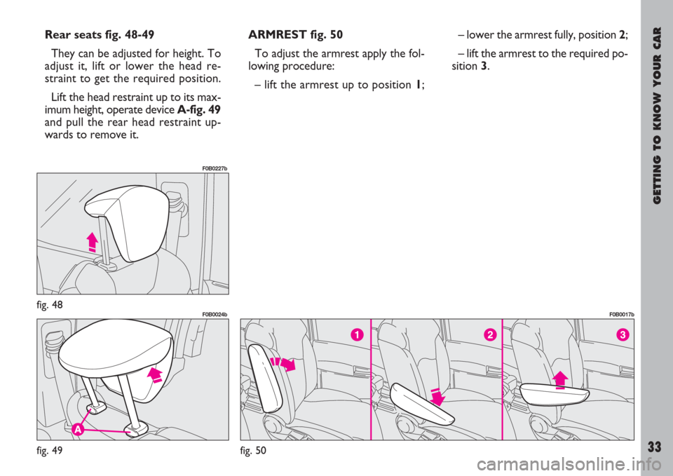
Rear seats fig. 48-49
They can be adjusted for height. To
adjust it, lift or lower the head re-
straint to get the required position.
Lift the head restraint up to its max-
imum height, operate device A-fig. 49
and pull the rear head restraint up-
wards to remove it.ARMREST fig. 50
To adjust the armrest apply the fol-
lowing procedure:
– lift the armrest up to position 1;– lower the armrest fully, position 2;
– lift the armrest to the required po-
sition 3.
Page 41 of 254
GETTING TO KNOW YOUR CAR
40
The pretensioner can
only be used once. After a
collision that has trig-
gered it, have it replaced at a Fi-
at Dealership. The device will last
for 10 years from the date of pro-
duction. Contact a Fiat Dealer-
ship to replace the pretensioners
as this date approaches.
Operations involving
banging, vibrations or
heating (exceeding 100°C
for a maximum of 6 hours) in the
area around the pretensioner
may trigger or damage the de-
vice. Vibrations from rough road
surfaces or accidental jolting
cause by mounting pavements
etc. do not have any effect on the
pretensioner. If, however, you
need any assistance, go to a Fiat
Dealership.
LOAD LIMITING DEVICES
This device reduces the load which
is normally exerted by the seat belts
on the passenger’s shoulder and chest
in a collision. It increases protection
by preventing the micro traumas
which are inevitable in road accidents.
The device is built into the front and
second row side seat belt reels.GENERAL INSTRUCTIONS
FOR THE USE OF THE SEAT
BELTS
The driver must make sure that all
occupants use their seat belts prop-
erly in accordance with local legisla-
tion.
Always fasten the seat belts before
starting.
For maximum safety,
keep the back of your seat
upright, lean back into it
and make sure the seat belt fits
closely across your chest and hips.
Make sure the seat belts on the
front and rear passengers are fas-
tened at all times. You increase
the risk of serious injury or death
in a collision if you travel with the
belts unfastened.
Page 48 of 254
GETTING TO KNOW YOUR CAR
47
The seat fitted with child restraint
system shall be set in the most back-
ward position.
You are recommended to choose
Kiddy Isofix since this seat has been
designed and tested specifically for this
vehicle. Kiddy Isofix has been type ap-
proved according to the European
Standard ECE-R44/03.
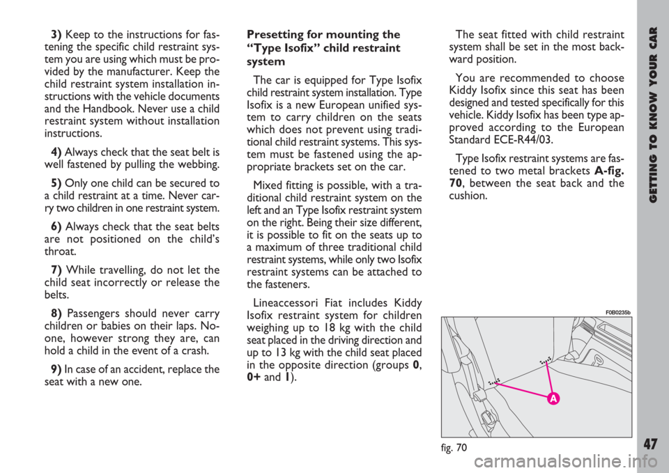
Type Isofix restraint systems are fas-
tened to two metal brackets A-fig.
70, between the seat back and the
cushion. 3)Keep to the instructions for fas-
tening the specific child restraint sys-
tem you are using which must be pro-
vided by the manufacturer. Keep the
child restraint system installation in-
structions with the vehicle documents
and the Handbook. Never use a child
restraint system without installation
instructions.
4)Always check that the seat belt is
well fastened by pulling the webbing.
5)Only one child can be secured to
a child restraint at a time. Never car-
ry two children in one restraint system.
6)Always check that the seat belts
are not positioned on the child’s
throat.
7)While travelling, do not let the
child seat incorrectly or release the
belts.
8)Passengers should never carry
children or babies on their laps. No-
one, however strong they are, can
hold a child in the event of a crash.
9) In case of an accident, replace the
seat with a new one.Presetting for mounting the
“Type Isofix” child restraint
system
The car is equipped for Type Isofix
child restraint system installation. Type
Isofix is a new European unified sys-
tem to carry children on the seats
which does not prevent using tradi-
tional child restraint systems. This sys-
tem must be fastened using the ap-
propriate brackets set on the car.
Mixed fitting is possible, with a tra-
ditional child restraint system on the
left and an Type Isofix restraint system
on the right. Being their size different,
it is possible to fit on the seats up to
a maximum of three traditional child
restraint systems, while only two Isofix
restraint systems can be attached to
the fasteners.
Lineaccessori Fiat includes Kiddy
Isofix restraint system for children
weighing up to 18 kg with the child
seat placed in the driving direction and
up to 13 kg with the child seat placed
in the opposite direction (groups 0,
0+and 1).
fig. 70
F0B0235b
Page 65 of 254
GETTING TO KNOW YOUR CAR
64
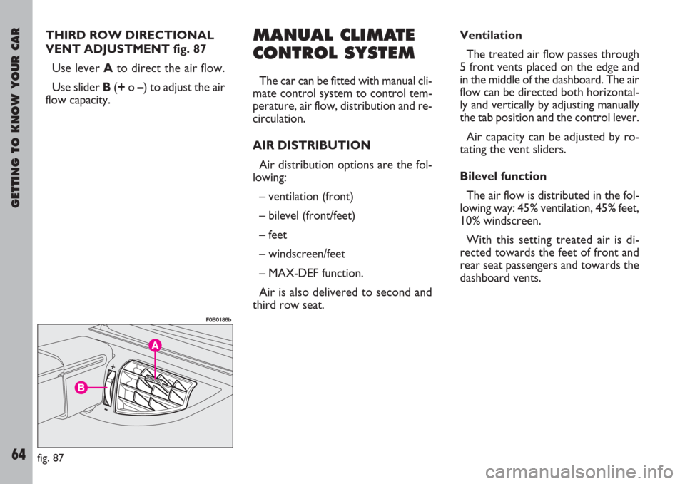
THIRD ROW DIRECTIONAL
VENT ADJUSTMENT fig. 87
Use lever A to direct the air flow.
Use sliderB(+o –) to adjust the air
flow capacity.MANUAL CLIMATE
CONTROL SYSTEM
The car can be fitted with manual cli-
mate control system to control tem-
perature, air flow, distribution and re-
circulation.
AIR DISTRIBUTION
Air distribution options are the fol-
lowing:
– ventilation (front)
– bilevel (front/feet)
– feet
– windscreen/feet
– MAX-DEF function.
Air is also delivered to second and
third row seat.Ventilation
The treated air flow passes through
5 front vents placed on the edge and
in the middle of the dashboard. The air
flow can be directed both horizontal-
ly and vertically by adjusting manually
the tab position and the control lever.
Air capacity can be adjusted by ro-
tating the vent sliders.
Bilevel function
The air flow is distributed in the fol-
lowing way: 45% ventilation, 45% feet,
10% windscreen.
With this setting treated air is di-
rected towards the feet of front and
rear seat passengers and towards the
dashboard vents.
fig. 87
F0B0186b
Page 66 of 254
Failure to replace the fil-
ter can reduce the cli-
mate control system’s ef-
ficiency considerably.
GETTING TO KNOW YOUR CAR
65
Feet
Air is directed towards the feet
through:
– three front vents for the first row
(2 on the driver’s side and 1 on the
passenger’s side);
– four vents on the floor (2 for the
second row and 2 for the third row).
Windscreen/feet
Air is distributed with the same per-
centage to the feet (40%) and wind-
screen vents (40%), but a small per-
centage is devoted to ventilation (20%)
in order to guarantee the passenger
compartment heating and to prevent
frosting.
This type of air distribution is applied
by the climate control system auto-
matic operation, especially when the
external temperature is very low and
it is necessary to direct some warm air
towards the driver’s hands.
MAX-DEF function
Air is completely directed to the
windscreen and front side windows.
This function is used for the wind-
screen/side window rapid defrost-ing/demisting and rear heated window
activation with only one operation.
Such function is activated manually
and enables the following functions:
– ventilation with maximum air ca-
pacity;
– air mixing completely hot;
– air recirculation off (outside air);
– compressor on;
– air distribution to the windscreen;
– rear heated window on.
When the MAX-DEF function is on
it is possible to alter the air capacity
and to deactivate the rear heated win-
dow.
The rear heated window works for
a limited time and turns off automati-
cally.AIR QUALITY
The system is fitted with a pollen fil-
ter which prevents dust particles and
pollen coming from the outside from
getting into the system.
Have the pollen filter checked at a
Fiat Dealership at least once a year,
possibly at the beginning of spring/
summer.
If the car is often used in dusty or
highly polluted areas, you should check
or change the pollen filter more fre-
quently.
Page 67 of 254
GETTING TO KNOW YOUR CAR
66
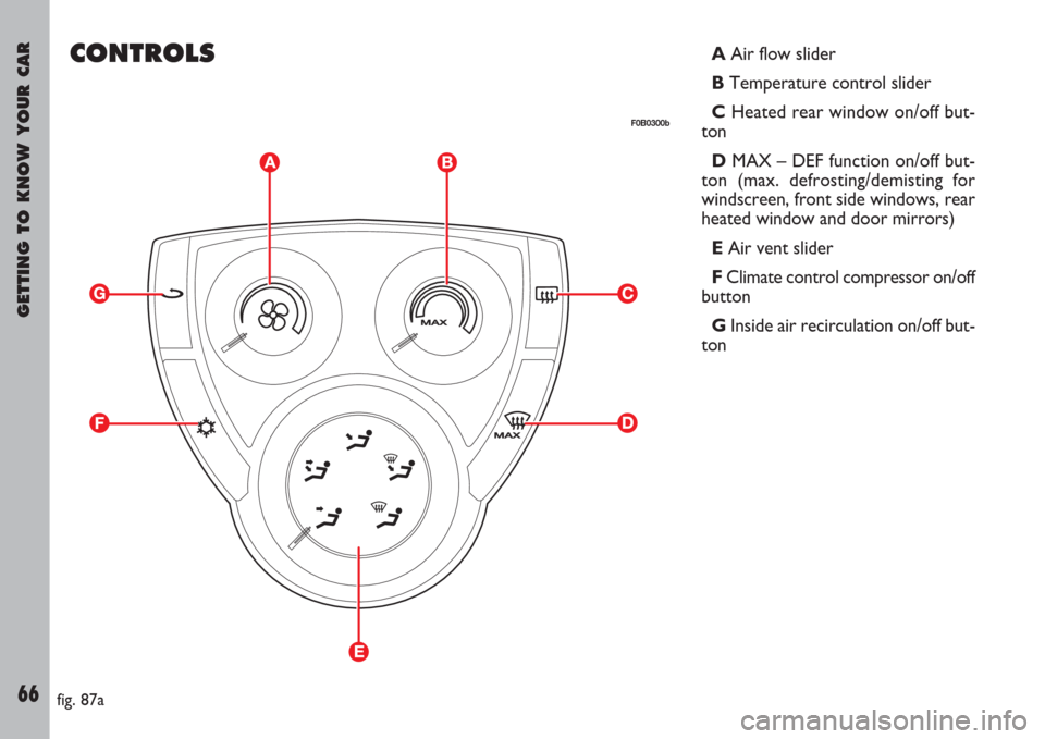
CONTROLSAAir flow slider
B Temperature control slider
C Heated rear window on/off but-
ton
DMAX – DEF function on/off but-
ton (max. defrosting/demisting for
windscreen, front side windows, rear
heated window and door mirrors)
EAir vent slider
FClimate control compressor on/off
button
GInside air recirculation on/off but-
ton
fig. 87a
F0B0300b