light FIAT ULYSSE 2009 2.G Repair Manual
[x] Cancel search | Manufacturer: FIAT, Model Year: 2009, Model line: ULYSSE, Model: FIAT ULYSSE 2009 2.GPages: 254, PDF Size: 3.56 MB
Page 155 of 254
IN AN EMERGENCY
154
Do not carry out this
procedure if you lack ex-
perience; if it is not done
correctly it can cause very in-
tense electrical discharges. In ad-
dition, the fluid contained in the
battery is poisonous and corro-
sive. Avoid contact with skin and
eyes. You are also advised not to
put naked flames or lighted cig-
arettes near the battery and not
to cause sparks.
Remember that until
the engine has started the
brake booster and elec-
trical power steering systems will
not work and a greater effort will
therefore be required to press
the brake pedal or turn the steer-
ing wheel.IF A TYRE
IS PUNCTURED
Certain versions (for versions/ mar-
kets, where provided) are fitted with
wheel identification and tyre inflation
sensors; pressure loss is signalled to
the driver in the following way:
pressure loss- the infotelematic
CONNECT system displays the relat-
ed message and a “gong” is emitted by
the system. Contact a Fiat Dealer-
ship;
punctured tyre- warning light
“STOP” comes on and the in-
fotelematic CONNECT system dis-
plays the related message together
with 3 consecutive “gong” sounds.
Change the wheel in the following
way.
The system can also display a dedi-
cated message in the event it should
not be able to detect the tyre pres-
sure. Under no circumstances
should a battery charger
be used to start the en-
gine: it could damage the elec-
tronic systems and in particular
the ignition and injection control
units.
BUMP STARTING
Do not bump start by
pushing, towing or coast-
ing downhill. This way of
starting could cause a
rush of fuel into the catalytic con-
verter and damage it beyond re-
pair.
153-183 ULYSSE ING:153-183 ULYSSE ING 13-11-2009 10:07 Pagina 154
Page 156 of 254
IN AN EMERGENCY
155
An incorrectly posi-
tioned jack may cause the
vehicle to fall. Do not use
the jack to lift loads exceeding
that indicated on the label at-
tached to the jack itself.Do not lubricate the bolt
threads before fitting
them back: they could
come loose.
Never start the engine when the
vehicle is jacked up.
If you are towing a trailer, re-
move the trailer before jacking
up the vehicle.Never tamper with the
inflation valve. Never
place tools between the
rim and the tyre.
Check the tyre and space-saver
spare wheel pressure regularly.
The tyre inflation pressure is
shown in the “Technical specifi-
cations” chapter.
The jack should only be
used to change a wheel
on the vehicle for which it
was designed. It should not be put
to other uses or employed to
raise other models. Under no cir-
cumstances should it be used
when carrying out repairs under
the vehicle.
Check the inflation pres-
sure of the tyres and the
spare wheel regularly. If
you change the type of wheels (al-
loy rims instead of steel rims) you
will have to change the entire set
of fastening bolts with another
set of suitably sized bolts.
You should keep the bolts in
case you decide to use the origi-
nal type of wheel later on.Signal the presence of
the stopped car according
to the laws in force: haz-
ard lights, reflecting triangle, etc.
Any passengers on board should
leave the car, especially if it is
heavily laden. Passengers should
stay away from oncoming traffic
while the wheel is being changed.
If the wheel is being changed on
a steep or badly surfaced road,
place wedges or other suitable
material under the wheels to
stop the car.
GENERAL INSTRUCTIONS
Observe the instructions on this and
the following pages to use the jack and
space-saver spare wheel correctly.
153-183 ULYSSE ING:153-183 ULYSSE ING 13-11-2009 10:07 Pagina 155
Page 160 of 254
IN AN EMERGENCY
159
When you have finished:
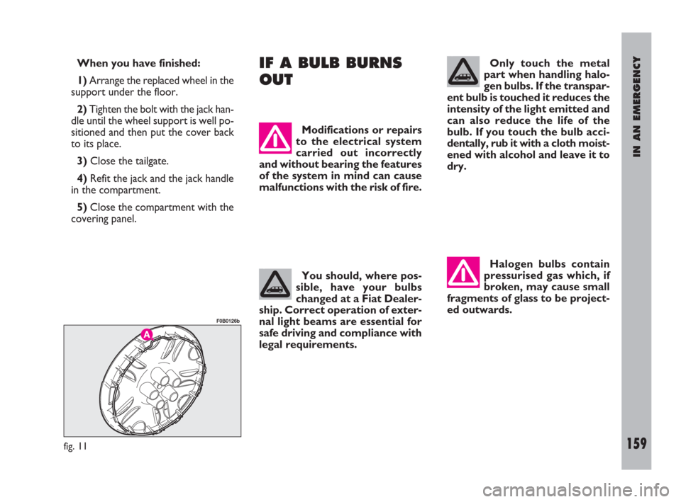
1)Arrange the replaced wheel in the
support under the floor.
2)Tighten the bolt with the jack han-
dle until the wheel support is well po-
sitioned and then put the cover back
to its place.
3)Close the tailgate.
4)Refit the jack and the jack handle
in the compartment.
5)Close the compartment with the
covering panel.IF A BULB BURNS
OUT
Modifications or repairs
to the electrical system
carried out incorrectly
and without bearing the features
of the system in mind can cause
malfunctions with the risk of fire.
You should, where pos-
sible, have your bulbs
changed at a Fiat Dealer-
ship. Correct operation of exter-
nal light beams are essential for
safe driving and compliance with
legal requirements.
fig. 11
F0B0126b
Only touch the metal
part when handling halo-
gen bulbs. If the transpar-
ent bulb is touched it reduces the
intensity of the light emitted and
can also reduce the life of the
bulb. If you touch the bulb acci-
dentally, rub it with a cloth moist-
ened with alcohol and leave it to
dry.
Halogen bulbs contain
pressurised gas which, if
broken, may cause small
fragments of glass to be project-
ed outwards.
153-183 ULYSSE ING:153-183 ULYSSE ING 13-11-2009 10:07 Pagina 159
Page 161 of 254
IN AN EMERGENCY
160
GENERAL INSTRUCTIONS
– When a light is not working, check
that it has not fused before changing
the bulb.
– For the location of the fuses, refer
to “If a fuse blows” in this chapter.
– Before replacing a bulb that does
not work, check that the contacts are
not oxidised.
– Burnt-out bulbs must be replaced
with ones of the same type and pow-
er.
– Always check the height of the
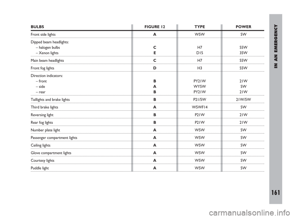
headlight beam after changing a bulb.TYPES OF BULBS fig. 12
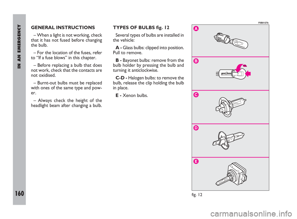
Several types of bulbs are installed in
the vehicle:
A -Glass bulbs: clipped into position.
Pull to remove.
B -Bayonet bulbs: remove from the
bulb holder by pressing the bulb and
turning it anticlockwise.
C-D -Halogen bulbs: to remove the
bulb, release the clip holding the bulb
in place.
E -Xenon bulbs.
fig. 12
F0B0127b
153-183 ULYSSE ING:153-183 ULYSSE ING 13-11-2009 10:07 Pagina 160
Page 162 of 254
IN AN EMERGENCY
161
BULBS
Front side lights
Dipped beam headlights:
– halogen bulbs
– Xenon lights
Main beam headlights
Front fog lights
Direction indicators:
– front
– side
– rear
Taillights and brake lights
Third brake lights
Reversing light
Rear fog lights
Number plate light
Passenger compartment lights
Ceiling lights
Glove compartment lights
Courtesy lights
Puddle lightFIGURE 12
A
C
E
C
D
B
A
B
B
A
B
B
A
A
A
A
A
ATYPE
W5W
H7
D15
H7
H3
PY21W
WY5W
PY21W
P21/5W
W5WF14
P21W
P21W
W5W
W5W
W5W
W5W
W5W
W5WPOWER
5W
55W
35W
55W
55W
21W
5W
21W
21W/5W
5W
21W
21W
5W
5W
5W
5W
5W
5W
153-183 ULYSSE ING:153-183 ULYSSE ING 13-11-2009 10:07 Pagina 161
Page 163 of 254
IN AN EMERGENCY
162
IF AN EXTERIOR
LIGHT BURNS OUT
Modifications or repairs
to the electrical system
carried out incorrectly
and without bearing the features
of the system in mind can cause
malfunctions with the risk of fire.
IMPORTANTSee “If a bulb burns
out” for information on bulb types and
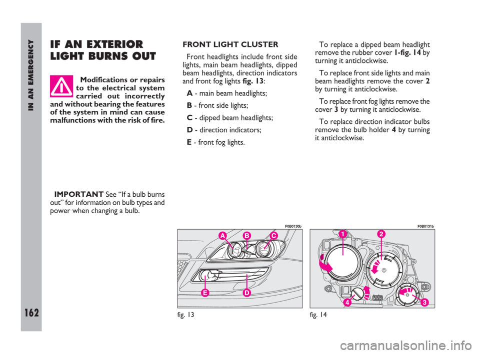
power when changing a bulb.FRONT LIGHT CLUSTER
Front headlights include front side
lights, main beam headlights, dipped
beam headlights, direction indicators
and front fog lights fig. 13:
A- main beam headlights;
B- front side lights;
C- dipped beam headlights;
D- direction indicators;
E- front fog lights.To replace a dipped beam headlight
remove the rubber cover 1-fig. 14by
turning it anticlockwise.
To replace front side lights and main
beam headlights remove the cover 2
by turning it anticlockwise.
To replace front fog lights remove the
cover 3by turning it anticlockwise.
To replace direction indicator bulbs
remove the bulb holder 4by turning
it anticlockwise.
fig. 13
F0B0130b
fig. 14
F0B0131b
153-183 ULYSSE ING:153-183 ULYSSE ING 13-11-2009 10:07 Pagina 162
Page 164 of 254
IN AN EMERGENCY
163
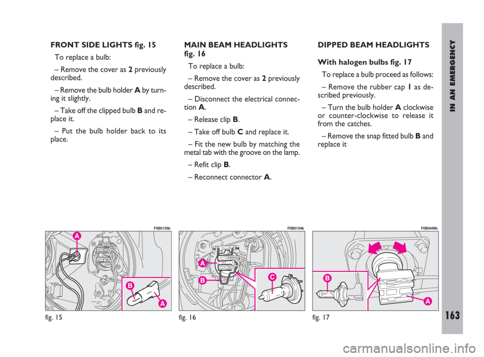
FRONT SIDE LIGHTS fig. 15
To replace a bulb:
– Remove the cover as 2previously
described.
– Remove the bulb holder Aby turn-
ing it slightly.
– Take off the clipped bulb Band re-
place it.
– Put the bulb holder back to its
place.MAIN BEAM HEADLIGHTS
fig. 16
To replace a bulb:
– Remove the cover as 2previously
described.
– Disconnect the electrical connec-
tion A.
– Release clip B.
– Take off bulb Cand replace it.
– Fit the new bulb by matching the
metal tab with the groove on the lamp.
– Refit clip B.
– Reconnect connector A.DIPPED BEAM HEADLIGHTS
With halogen bulbs fig. 17
To replace a bulb proceed as follows:
– Remove the rubber cap 1as de-
scribed previously.
– Turn the bulb holder Aclockwise
or counter-clockwise to release it
from the catches.
– Remove the snap fitted bulb Band
replace it
fig. 15
F0B0135b
fig. 16
F0B0134b
fig. 17
F0B0446b
153-183 ULYSSE ING:153-183 ULYSSE ING 13-11-2009 10:07 Pagina 163
Page 166 of 254
IN AN EMERGENCY
165
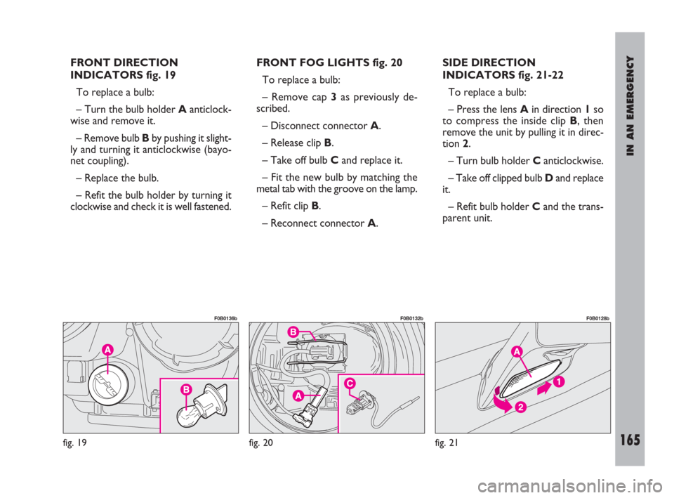
FRONT DIRECTION
INDICATORS fig. 19
To replace a bulb:
– Turn the bulb holder Aanticlock-
wise and remove it.
– Remove bulb Bby pushing it slight-
ly and turning it anticlockwise (bayo-
net coupling).
– Replace the bulb.
– Refit the bulb holder by turning it
clockwise and check it is well fastened.FRONT FOG LIGHTS fig. 20
To replace a bulb:
– Remove cap 3as previously de-
scribed.
– Disconnect connector A.
– Release clip B.
– Take off bulb Cand replace it.
– Fit the new bulb by matching the
metal tab with the groove on the lamp.
– Refit clip B.
– Reconnect connector A.SIDE DIRECTION
INDICATORS fig. 21-22
To replace a bulb:
– Press the lens Ain direction 1so
to compress the inside clip B, then
remove the unit by pulling it in direc-
tion 2.
– Turn bulb holder C anticlockwise.
– Take off clipped bulb Dand replace
it.
– Refit bulb holder Cand the trans-
parent unit.
fig. 19
F0B0136b
fig. 20
F0B0132b
fig. 21
F0B0128b
153-183 ULYSSE ING:153-183 ULYSSE ING 13-11-2009 10:07 Pagina 165
Page 167 of 254
IN AN EMERGENCY
166
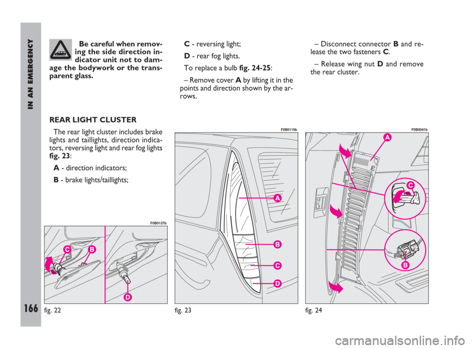
Be careful when remov-
ing the side direction in-
dicator unit not to dam-
age the bodywork or the trans-
parent glass.
REAR LIGHT CLUSTER
The rear light cluster includes brake
lights and taillights, direction indica-
tors, reversing light and rear fog lights
fig. 23:
A- direction indicators;
B- brake lights/taillights;C- reversing light;
D- rear fog lights.
To replace a bulb fig. 24-25:
– Remove cover Aby lifting it in the
points and direction shown by the ar-
rows.– Disconnect connector Band re-
lease the two fasteners C.
– Release wing nut Dand remove
the rear cluster.
fig. 22
F0B0137b
fig. 24
F0B0041b
fig. 23
F0B0115b
153-183 ULYSSE ING:153-183 ULYSSE ING 13-11-2009 10:07 Pagina 166
Page 168 of 254
IN AN EMERGENCY
167
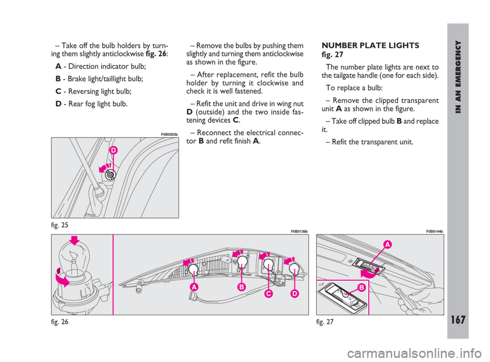
– Take off the bulb holders by turn-
ing them slightly anticlockwise fig. 26:
A- Direction indicator bulb;
B- Brake light/taillight bulb;
C- Reversing light bulb;
D- Rear fog light bulb.– Remove the bulbs by pushing them
slightly and turning them anticlockwise
as shown in the figure.
– After replacement, refit the bulb
holder by turning it clockwise and
check it is well fastened.
– Refit the unit and drive in wing nut
D(outside) and the two inside fas-
tening devices C.
– Reconnect the electrical connec-
tor Band refit finish A.NUMBER PLATE LIGHTS
fig. 27
The number plate lights are next to
the tailgate handle (one for each side).
To replace a bulb:
– Remove the clipped transparent
unit Aas shown in the figure.
– Take off clipped bulb Band replace
it.
– Refit the transparent unit.
fig. 26
F0B0138b
fig. 27
F0B0144bfig. 25
F0B0263b
153-183 ULYSSE ING:153-183 ULYSSE ING 13-11-2009 10:07 Pagina 167