check engine light FIAT UNO 1983 Service User Guide
[x] Cancel search | Manufacturer: FIAT, Model Year: 1983, Model line: UNO, Model: FIAT UNO 1983Pages: 303, PDF Size: 10.36 MB
Page 48 of 303
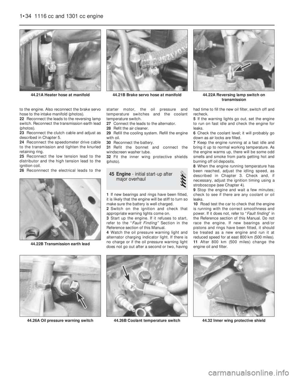
to the engine. Also reconnect the brake servo
hose to the intake manifold (photos).
22Reconnect the leads to the reversing lamp
switch. Reconnect the transmission earth lead
(photos).
23Reconnect the clutch cable and adjust as
described in Chapter 5.
24Reconnect the speedometer drive cable
to the transmission and tighten the knurled
retaining ring.
25Reconnect the low tension lead to the
distributor and the high tension lead to the
ignition coil.
26Reconnnect the electrical leads to thestarter motor, the oil pressure and
temperature switches and the coolant
temperature switch.
27Connect the leads to the alternator.
28Refit the air cleaner.
29Refill the cooling system. Refill the engine
with oil.
30Reconnect the battery.
31Refit the bonnet and connect the
windscreen washer tube.
32Fit the inner wing protective shields
(photo).
45 Engine- initial start-up after
major overhaul
4
1If new bearings and rings have been fitted,
it is likely that the engine will be stiff to turn so
make sure the battery is well charged.
2Switch on the ignition and check that
appropriate warning lights come on.
3Start up the engine. If it refuses to start,
refer to the “Fault Finding” Section in the
Reference section of this Manual.
4Watch the oil pressure warning light and
alternator charging indicator light. If there is
no charge or if the oil pressure warning light
does not go out after a second or two, havinghad time to fill the new oil filter, switch off and
recheck.
5If the warning lights go out, set the engine
to run on fast idle and check the engine for
leaks.
6Check the coolant level; it will probably go
down as air locks are filled.
7Keep the engine running at a fast idle and
bring it up to normal working temperature. As
the engine warms up, there will be some odd
smells and smoke from parts getting hot and
burning off oil deposits.
8When the engine running temperature has
been reached, adjust the idling speed, as
described in Chapter 3. Check and, if
necessary, adjust the ignition timing using a
stroboscope (see Chapter 4).
9Stop the engine and wait a few minutes;
check to see if there are any coolant or oil
leaks.
10Road test the car to check that the engine
is running with the correct smoothness and
power. If it does not, refer to “Fault finding” in
the Reference section of this Manual. Do not
race the engine. If new bearings and/or
pistons and rings have been fitted, it should
be treated as a new engine and run it at
reduced speed for at east 800 km (500 miles).
11After 800 km (500 miles) change the
engine oil and filter.
1•34 1116 cc and 1301 cc engine
44.32 Inner wing protective shield44.26B Coolant temperature switch44.26A Oil pressure warning switch
44.22B Transmission earth lead
44.22A Reversing lamp switch on
transmission44.21B Brake servo hose at manifold44.21A Heater hose at manifold
Page 53 of 303
inhibitor should be used. Again, a reputable
make giving full protection must be chosen
and renewed every two years. Inhibitors with
dyes are useful for finding leaks, and on some
makes the dye shows when the inhibiting
ability is finished.
4 Thermostat-
removal, testing and refitting
1
1The thermostat assembly is mounted on the
flywheel end of the cylinder block.
2Unfortunately, the thermostat/housing is a
complete unit and failure of the thermostat will
necessitate the purchase of the complete
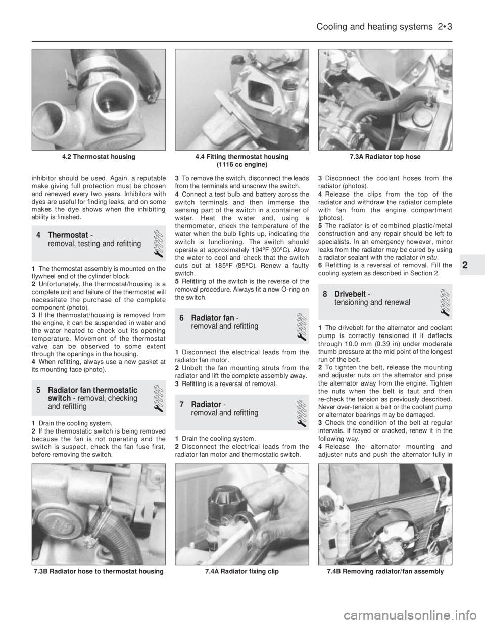
component (photo).
3If the thermostat/housing is removed from
the engine, it can be suspended in water and
the water heated to check out its opening
temperature. Movement of the thermostat
valve can be observed to some extent
through the openings in the housing.
4When refitting, always use a new gasket at
its mounting face (photo).
5 Radiator fan thermostatic
switch- removal, checking
and refitting
1
1Drain the cooling system.
2If the thermostatic switch is being removed
because the fan is not operating and the
switch is suspect, check the fan fuse first,
before removing the switch.3To remove the switch, disconnect the leads
from the terminals and unscrew the switch.
4Connect a test bulb and battery across the
switch terminals and then immerse the
sensing part of the switch in a container of
water. Heat the water and, using a
thermometer, check the temperature of the
water when the bulb lights up, indicating the
switch is functioning. The switch should
operate at approximately 194ºF (90ºC). Allow
the water to cool and check that the switch
cuts out at 185ºF (85ºC). Renew a faulty
switch.
5Refitting of the switch is the reverse of the
removal procedure. Always fit a new O-ring on
the switch.
6 Radiator fan-
removal and refitting
1
1Disconnect the electrical leads from the
radiator fan motor.
2Unbolt the fan mounting struts from the
radiator and lift the complete assembly away.
3Refitting is a reversal of removal.
7 Radiator-
removal and refitting
1
1Drain the cooling system.
2Disconnect the electrical leads from the
radiator fan motor and thermostatic switch.3Disconnect the coolant hoses from the
radiator (photos).
4Release the clips from the top of the
radiator and withdraw the radiator complete
with fan from the engine compartment
(photos).
5The radiator is of combined plastic/metal
construction and any repair should be left to
specialists. In an emergency however, minor
leaks from the radiator may be cured by using
a radiator sealant with the radiator in situ.
6Refitting is a reversal of removal. Fill the
cooling system as described in Section 2.
8 Drivebelt-
tensioning and renewal
1
1The drivebelt for the alternator and coolant
pump is correctly tensioned if it deflects
through 10.0 mm (0.39 in) under moderate
thumb pressure at the mid point of the longest
run of the belt.
2To tighten the belt, release the mounting
and adjuster nuts on the alternator and prise
the alternator away from the engine. Tighten
the nuts when the belt is taut and then
re-check the tension as previously described.
Never over-tension a belt or the coolant pump
or alternator bearings may be damaged.
3Check the condition of the belt at regular
intervals. If frayed or cracked, renew it in the
following way.
4Release the alternator mounting and
adjuster nuts and push the alternator fully in
Cooling and heating systems 2•3
7.3A Radiator top hose4.4 Fitting thermostat housing
(1116 cc engine)4.2 Thermostat housing
7.4B Removing radiator/fan assembly7.4A Radiator fixing clip7.3B Radiator hose to thermostat housing
2
Page 69 of 303
Anti-flooding device (automatic)
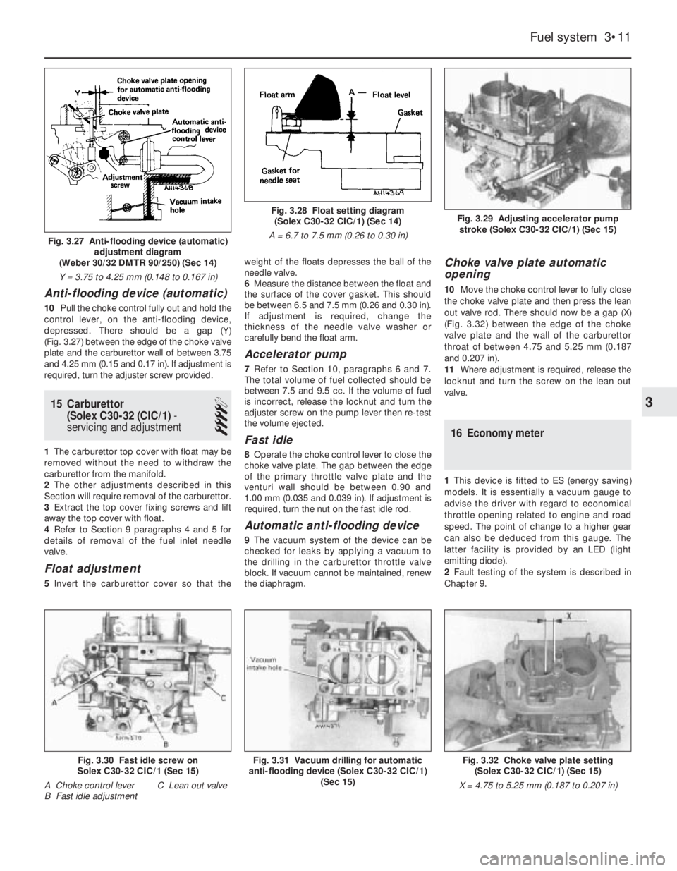
10Pull the choke control fully out and hold the
control lever, on the anti-flooding device,
depressed. There should be a gap (Y)
(Fig. 3.27) between the edge of the choke valve
plate and the carburettor wall of between 3.75
and 4.25 mm (0.15 and 0.17 in). If adjustment is
required, turn the adjuster screw provided.
15 Carburettor
(Solex C30-32 (CIC/1)-
servicing and adjustment
4
1The carburettor top cover with float may be
removed without the need to withdraw the
carburettor from the manifold.
2The other adjustments described in this
Section will require removal of the carburettor.
3Extract the top cover fixing screws and lift
away the top cover with float.
4Refer to Section 9 paragraphs 4 and 5 for
details of removal of the fuel inlet needle
valve.
Float adjustment
5Invert the carburettor cover so that theweight of the floats depresses the ball of the
needle valve.
6Measure the distance between the float and
the surface of the cover gasket. This should
be between 6.5 and 7.5 mm (0.26 and 0.30 in).
If adjustment is required, change the
thickness of the needle valve washer or
carefully bend the float arm.
Accelerator pump
7Refer to Section 10, paragraphs 6 and 7.
The total volume of fuel collected should be
between 7.5 and 9.5 cc. If the volume of fuel
is incorrect, release the locknut and turn the
adjuster screw on the pump lever then re-test
the volume ejected.
Fast idle
8Operate the choke control lever to close the
choke valve plate. The gap between the edge
of the primary throttle valve plate and the
venturi wall should be between 0.90 and
1.00 mm (0.035 and 0.039 in). If adjustment is
required, turn the nut on the fast idle rod.
Automatic anti-flooding device
9The vacuum system of the device can be
checked for leaks by applying a vacuum to
the drilling in the carburettor throttle valve
block. If vacuum cannot be maintained, renew
the diaphragm.
Choke valve plate automatic
opening
10Move the choke control lever to fully close
the choke valve plate and then press the lean
out valve rod. There should now be a gap (X)
(Fig. 3.32) between the edge of the choke
valve plate and the wall of the carburettor
throat of between 4.75 and 5.25 mm (0.187
and 0.207 in).
11Where adjustment is required, release the
locknut and turn the screw on the lean out
valve.
16 Economy meter
1This device is fitted to ES (energy saving)
models. It is essentially a vacuum gauge to
advise the driver with regard to economical
throttle opening related to engine and road
speed. The point of change to a higher gear
can also be deduced from this gauge. The
latter facility is provided by an LED (light
emitting diode).
2Fault testing of the system is described in
Chapter 9.
Fuel system 3•11
Fig. 3.29 Adjusting accelerator pump
stroke (Solex C30-32 CIC/1) (Sec 15)Fig. 3.28 Float setting diagram
(Solex C30-32 CIC/1) (Sec 14)
A = 6.7 to 7.5 mm (0.26 to 0.30 in)
Fig. 3.32 Choke valve plate setting
(Solex C30-32 CIC/1) (Sec 15)
X = 4.75 to 5.25 mm (0.187 to 0.207 in)Fig. 3.30 Fast idle screw on
Solex C30-32 CIC/1 (Sec 15)
A Choke control lever C Lean out valve
B Fast idle adjustmentFig. 3.31 Vacuum drilling for automatic
anti-flooding device (Solex C30-32 CIC/1)
(Sec 15)
3
Fig. 3.27 Anti-flooding device (automatic)
adjustment diagram
(Weber 30/32 DMTR 90/250) (Sec 14)
Y = 3.75 to 4.25 mm (0.148 to 0.167 in)
Page 70 of 303
19.7A Exhaust pipe support rings
17 Accelerator cable-
adjustment and renewal
2
1The socket type cable end fitting is
detached from the carburettor throttle lever
simply by prising it off the ball stud.
2Adjustment can be carried out by releasing
the locknut and turning the end fitting. With
the accelerator pedal fully depressed, check
that full throttle can be obtained at the
carburettor.
3To renew the cable, prise off the end fitting
from the carburettor throttle lever.
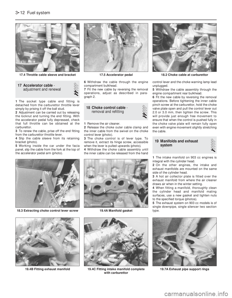
4Slip the cable sleeve from its retaining
bracket (photo).
5Working inside the car under the facia
panel, slip the cable from the fork at the top of
the accelerator pedal arm (photo). 6Withdraw the cable through the engine
compartment bulkhead.
7Fit the new cable by reversing the removal
operations, adjust as described in para-
graph 2.
18 Choke control cable-
removal and refitting
2
1Remove the air cleaner.
2Release the choke outer cable clamp and
the inner cable from the swivel on the choke
control lever (photo).
3The choke control is of lever type. To
remove it, extract its hinge screw, accessible
when the lever is pulled upwards (photo).
4Withdraw the choke cable assembly until
the inner cable can be released from the handcontrol lever and the choke warning lamp lead
unplugged.
5Withdraw the cable assembly through the
engine compartment rear bulkhead.
6Fit the new cable by reversing the removal
operations. Before tightening the inner cable
pinch screw at the carburettor, hold the choke
valve plate open and pull the control lever out
2.0 or 3.0 mm, then tighten the screw. This
will provide just enough free movement to
ensure that when the control is pushed fully in
the choke valve plate will remain fully open
even with engine movement slightly stretching
the cable.
19 Manifolds and exhaust
system
1
1The intake manifold on 903 cc engines is
integral with the cylinder head.
2On the other engines, the intake and
exhaust manifolds are mounted on the same
side of the cylinder head.
3A hot air collector plate is fitted over the
exhaust manifold from where the air cleaner
draws air when in the winter setting.
4When fitting a manifold, thoroughly clean
the cylinder head and manifold mating
surfaces, use a new gasket and tighten nuts
to the specified torque (photos).
5The exhaust system on 903 cc models is of
single downpipe, single silencer two section
type.
3•12 Fuel system
19.4C Fitting intake manifold complete
with carburettor19.4B Fitting exhaust manifold
19.4A Manifold gasket18.3 Extracting choke control lever screw
18.2 Choke cable at carburettor17.5 Accelerator pedal17.4 Throttle cable sleeve and bracket
Page 74 of 303
outwards, they rotate the cam relative to the
distributor shaft, and so advance the spark.
The weights are held in position by two
springs and it is the tension of the springs
which is largely responsible for correct spark
advancement.
The vacuum advance is controlled by a
diaphragm capsule connected to the
carburettor venturi. The vacuum pressure
varies according to the throttle valve plate
opening and so adjusts the ignition advance
in accordance with the engine requirements.
Digiplex ignition system
This electronic system eliminates the
mechanical contact breaker and centrifugal
advance mechanism of conventional
distributors and uses an electronic control
unit to provide advance values according to
engine speed and load. No provision is made
for adjustment of the ignition timing.
Information relayed to the control unit is
provided by two magnetic sensors which
monitor engine speed and TDC directly from
the engine crankshaft.
A vacuum sensor in the control unit
converts intake manifold vacuum into an
electric signal.
The control unit selects the optimum
advance angle required and a closed
magnetic circuit resin coil guarantees a spark
owing to the low primary winding resistance.
Five hundred and twelve advance values
are stored in the control unit memory to suit
any combination of engine operating
conditions.
No maintenance is required to the
distributor used on this system.
Distributor drive
The mechanical breaker type distributor on
903 cc engines and the Digiplex type
distributor on 903 cc ES engines are mounted
on the cylinder head and driven from a gear
on the camshaft through a shaft which also
drives the oil pump.
The distributor on 1116 cc and 1301 cc
engines is mounted on the crankcase and is
driven from a gear on the auxiliary shaft as is
also the oil pump.
2 Mechanical contact breaker
- points servicing
3
1At the intervals specified in “Routine
Maintenance”, prise down the clips on the
distributor cap and place the cap with high
tension leads to one side.
2Pull off the rotor.
3Remove the spark shield. Mechanical wear
of the contact breaker reduces the gap.
Electrical wear builds up a “pip” of burned
metal on one of the contacts. This
|prevents the gap being measured for
re-adjustment, and also spoils the electric
circuit.
Ducellier type distributor
4To remove the contact breaker movable
arm, extract the clip and take off the washer
from the top of the pivot post.
5Extract the screw and remove the fixed
contact arm.
6Clean the points by rubbing the surfaces on
a fine abrasive such as an oil stone. The point
surface should be shaped to a gentle convex
curve. All the “pip” burned onto one contact
must be removed. It is not necessary to go on
until all traces of the crater have been
removed from the other. There is enough
metal on the contacts to allow this to be done
once. At alternate services, fit new points.
Wash debris off cleaned points and
preservatives off new ones.
7Now the distributor should be lubricated.
This lubrication is important for the correct
mechanical function of the distributor, but
excess lubrication will ruin the electrical
circuits, and give difficult starting.
8Whilst the contact breaker is off, squirt
some engine oil into the bottom part of the
distributor, onto the centrifugal advance
mechanism below the plate.
9Wet with oil the felt pad on the top of the
distributor spindle, normally covered by the
rotor arm.
10Put just a drip of oil on the pivot for the
moving contact.11Smear a little general purpose grease
onto the cam, and the heel of the moving
contact breaker.
12Refit the contact points and then set the
gap in the following way.
13Turn the crankshaft by applying a spanner
to the pulley nut or by jacking up a front
wheel, engaging top gear and turning the
roadwheel in the forward direction of
travel. Keep turning until the plastic
heel of the movable contact arm is on the
high point of a cam lobe on the distributor
shaft.
14Set the points gap by moving the fixed
contact arm until the specified feeler blades
are a sliding fit. Tighten the fixed contact arm
screw.
15Check the contact end of the rotor arm.
Remove any slightly burnt deposits using fine
abrasive paper. Severe erosion will
necessitate renewal of the rotor.
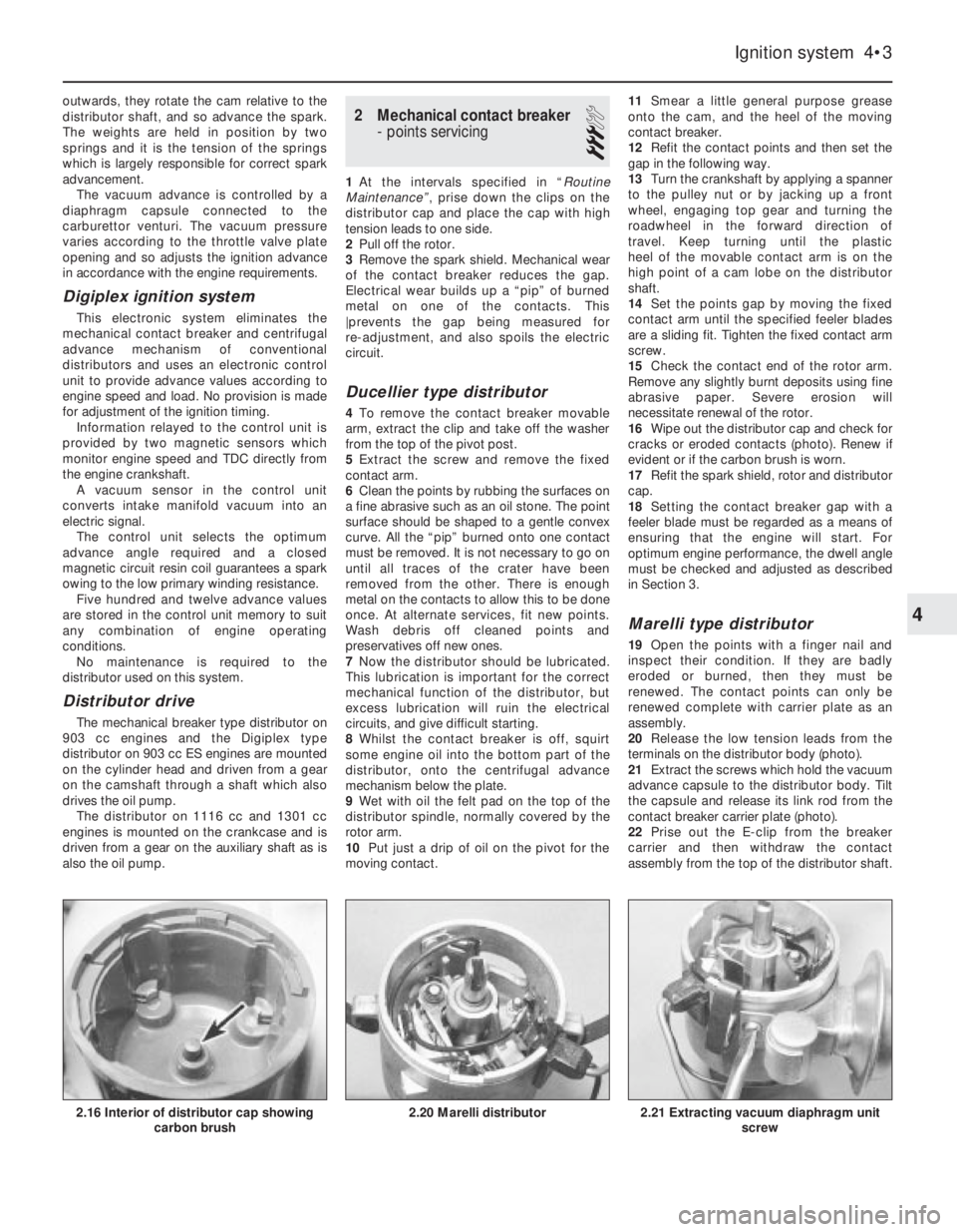
16Wipe out the distributor cap and check for
cracks or eroded contacts (photo). Renew if
evident or if the carbon brush is worn.
17Refit the spark shield, rotor and distributor
cap.
18Setting the contact breaker gap with a
feeler blade must be regarded as a means of
ensuring that the engine will start. For
optimum engine performance, the dwell angle
must be checked and adjusted as described
in Section 3.
Marelli type distributor
19Open the points with a finger nail and
inspect their condition. If they are badly
eroded or burned, then they must be
renewed. The contact points can only be
renewed complete with carrier plate as an
assembly.
20Release the low tension leads from the
terminals on the distributor body (photo).
21Extract the screws which hold the vacuum
advance capsule to the distributor body. Tilt
the capsule and release its link rod from the
contact breaker carrier plate (photo).
22Prise out the E-clip from the breaker
carrier and then withdraw the contact
assembly from the top of the distributor shaft.
Ignition system 4•3
2.21 Extracting vacuum diaphragm unit
screw2.20 Marelli distributor2.16 Interior of distributor cap showing
carbon brush
4
Page 75 of 303
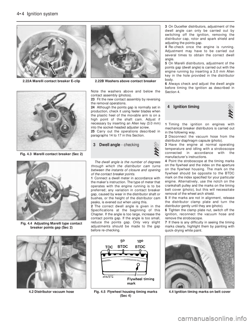
Note the washers above and below the
contact assembly (photos).
23Fit the new contact assembly by reversing
the removal operations.
24Although the points gap is normally set in
production, check it using feeler blades when
the plastic heel of the movable arm is on a
high point of the shaft cam. Adjust if
necessary by inserting an Allen key (3.0 mm)
into the socket-headed adjuster screw.
25Carry out the operations described in
paragraphs 14 to 17 in this Section.
3 Dwell angle- checking
3
The dwell angle is the number of degrees
through which the distributor cam turns
between the instants of closure and opening
of the contact breaker points.
1Connect a dwell meter in accordance with
the maker’s instruction. The type of meter that
operates with the engine running is to be
preferred; any variation in contact breaker
gap, caused by wear in the distributor shaft or
bushes, or the height of the distributor cam
peaks, is evened out when using this.
2The correct dwell angle is given in the
Specifications at the beginning of this
Chapter. If the angle is too large, increase the
contact points gap. If the angle is too small,
reduce the points gap. Only very slight
adjustments should be made to the gap
before re-checking.3On Ducellier distributors, adjustment of the
dwell angle can only be carried out by
switching off the ignition, removing the
distributor cap, rotor and spark shield and
adjusting the points gap.
4Re-check once the engine is running.
Adjustment may have to be carried out
several times to obtain the correct dwell
angle.
5On Marelli distributors, adjustment of the
points gap (dwell angle) is carried out with the
engine running by inserting a 3.0 mm Allen
key in the hole provided in the distributor
body.
6Always check and adjust the dwell angle
before timing the ignition as described in
Section 4.
4 Ignition timing
3
1Timing the ignition on engines with
mechanical breaker distributors is carried out
in the following way.
2Disconnect the vacuum hose from the
distributor diaphragm capsule (photo).
3Have the engine at normal operating
temperature and idling with a stroboscope
connected in accordance with the
manufacturer’s instructions.
4Point the stroboscope at the timing marks
on the flywheel and the index on the aperture
on the flywheel housing. The mark on the
flywheel should be opposite to the BTDC
mark on the index specified for your particular
engine. Alternatively, use the notch on the
crankshaft pulley and the marks on the timing
belt cover (photo), but this will necessitate
removal of the wheel arch shield.
5If the marks are not in alignment, release
the distributor clamp plate and turn the
distributor gently until they are (photo).
6Tighten the clamp plate nut, switch off the
ignition, reconnect the vacuum hose and
remove the stroboscope.
7If there is any difficulty in seeing the timing
marks clearly, highlight them by painting with
quick-drying white paint.
4•4 Ignition system
4.4 Ignition timing marks on belt coverFig. 4.5 Flywheel housing timing marks
(Sec 4)4.2 Distributor vacuum hose
Fig. 4.4 Adjusting Marelli type contact
breaker points gap (Sec 2)
Fig. 4.3 Marelli contact breaker (Sec 2)
2.22B Washers above contact breaker2.22A Marelli contact breaker E-clip
Page 79 of 303
this type is used and the engine is in good
condition, the spark plugs should not need
attention between scheduled replacement
intervals. Spark plug cleaning is rarely
necessary and should not be attempted unless
specialised equipment is available as damage
can easily be caused to the firing ends.
2At the specified intervals, the plugs should
be renewed. The condition of the spark plug
will also tell much about the overall condition
of the engine.
3If the insulator nose of the spark plug is
clean and white, with no deposits, this is
indicative of a weak mixture, or too hot a plug.
(A hot plug transfers heat away from the
electrode slowly - a cold plug transfers it away
quickly.)
4If the tip of the insulator nose is covered
with sooty black deposits, then this is
indicative that the mixture is too rich. Should
the plug be black and oily, then it is likely that
the engine is fairly worn, as well as the mixture
being too rich.
5The spark plug gap is of considerable
importance, as, if it is too large or too small
the size of the spark and its efficiency will be
seriously impaired. The spark plug gap should
be set to the gap shown in the Specifications
for the best results.
6To set it, measure the gap with a feeler
gauge, and then bend open, or close, the
outer plug electrode until the correct gap is
achieved. The centre electrode should never
be bent as this may crack the insulation and
cause plug failure, if nothing worse.
7When fitting new plugs, check that the plug
seats in the cylinder head are quite clean.
Refit the leads from the distributor in the
correct firing order, which is 1-3-4-2; No 1cylinder being the one nearest the flywheel
housing (903 cc) or timing belt (1116 or
1301 cc). The distributor cap is marked with
the HT lead numbers to avoid any confusion.
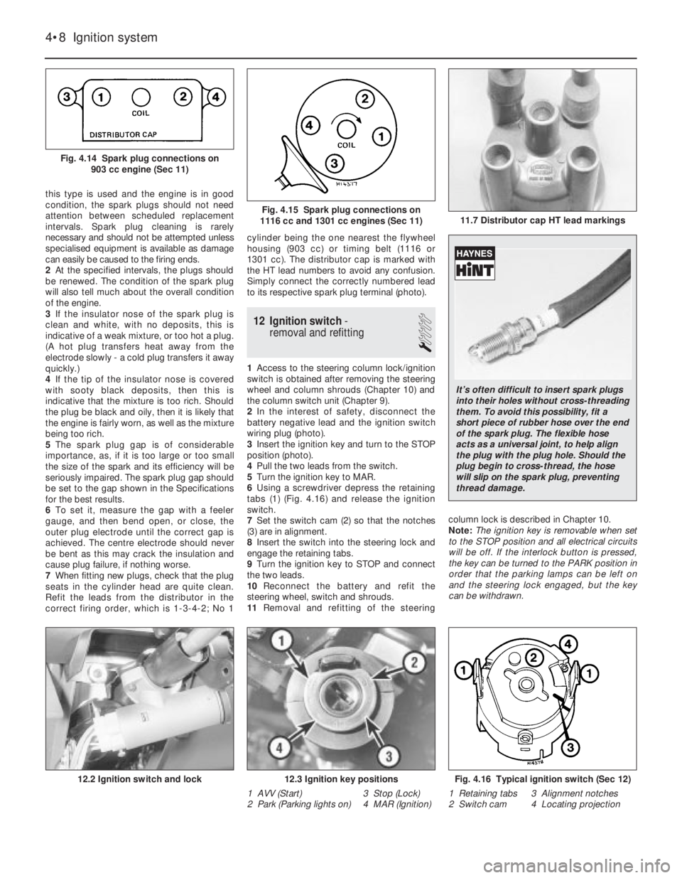
Simply connect the correctly numbered lead
to its respective spark plug terminal (photo).
12 Ignition switch-
removal and refitting
1
1Access to the steering column lock/ignition
switch is obtained after removing the steering
wheel and column shrouds (Chapter 10) and
the column switch unit (Chapter 9).
2In the interest of safety, disconnect the
battery negative lead and the ignition switch
wiring plug (photo).
3Insert the ignition key and turn to the STOP
position (photo).
4Pull the two leads from the switch.
5Turn the ignition key to MAR.
6Using a screwdriver depress the retaining
tabs (1) (Fig. 4.16) and release the ignition
switch.
7Set the switch cam (2) so that the notches
(3) are in alignment.
8Insert the switch into the steering lock and
engage the retaining tabs.
9Turn the ignition key to STOP and connect
the two leads.
10Reconnect the battery and refit the
steering wheel, switch and shrouds.
11Removal and refitting of the steeringcolumn lock is described in Chapter 10.
Note: The ignition key is removable when set
to the STOP position and all electrical circuits
will be off. If the interlock button is pressed,
the key can be turned to the PARK position in
order that the parking lamps can be left on
and the steering lock engaged, but the key
can be withdrawn.
4•8 Ignition system
Fig. 4.16 Typical ignition switch (Sec 12)
1 Retaining tabs 3 Alignment notches
2 Switch cam 4 Locating projection12.3 Ignition key positions
1 AVV (Start) 3 Stop (Lock)
2 Park (Parking lights on) 4 MAR (Ignition)12.2 Ignition switch and lock
11.7 Distributor cap HT lead markingsFig. 4.15 Spark plug connections on
1116 cc and 1301 cc engines (Sec 11)
Fig. 4.14 Spark plug connections on
903 cc engine (Sec 11)
It’s often difficult to insert spark plugs
into their holes without cross-threading
them. To avoid this possibility, fit a
short piece of rubber hose over the end
of the spark plug. The flexible hose
acts as a universal joint, to help align
the plug with the plug hole. Should the
plug begin to cross-thread, the hose
will slip on the spark plug, preventing
thread damage.
Page 91 of 303
1 General description
The electrical system is of 12 volt negative
earth type and employs a belt-driven
alternator and a pre-engaged type starter
motor.
The models in the range are all adequately
equipped with electrical accessories, while SX
versions also have power windows and
centralised door locking plus a check control
system (Section 34).
2 Battery- inspection, charging,
removal and refitting
2
1The battery is of maintenance-free type and
under normal circumstances, no topping up
will be required, but regularly check that the
electrolyte level is between the minimum and
maximum lines on the translucent battery
casing.
2If the electrolyte level does drop below theminimum line, suspect a leak in the battery
casing or that the alternator is overcharging. If
the latter is the case, rectify the alternator fault
and then prise out the two rectangular plugs
from the top of the battery and top up with
distilled or purified water.
3Always keep the battery terminals clean
and smear them with petroleum jelly to
prevent corrosion.
4The battery will normally be kept fully
charged by the alternator, but it is possible for
the battery to become discharged if the daily
mileage is very low with much use being
made of the starter and electrical accessories.
5When the battery begins to deteriorate with
age it may also require a boost from a mains
charger.
6Disconnect both battery leads before
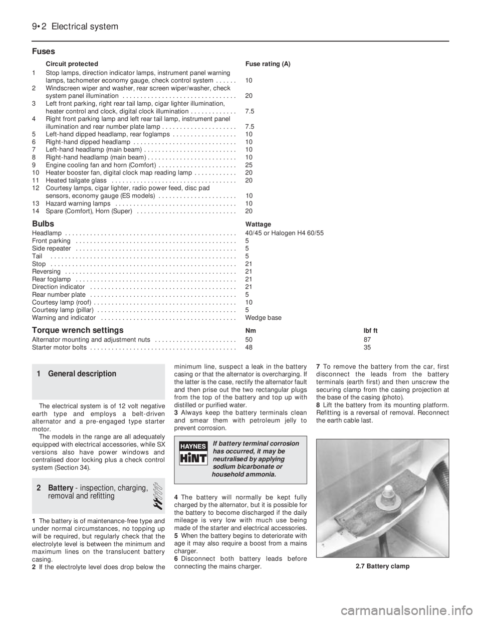
connecting the mains charger. 7To remove the battery from the car, first
disconnect the leads from the battery
terminals (earth first) and then unscrew the
securing clamp from the casing projection at
the base of the casing (photo).
8Lift the battery from its mounting platform.
Refitting is a reversal of removal. Reconnect
the earth cable last.
Fuses
Circuit protected Fuse rating (A)
1 Stop lamps, direction indicator lamps, instrument panel warning
lamps, tachometer economy gauge, check control system . . . . . . 10
2 Windscreen wiper and washer, rear screen wiper/washer, check
system panel illumination . . . . . . . . . . . . . . . . . . . . . . . . . . . . . . . . 20
3 Left front parking, right rear tail lamp, cigar lighter illumination,
heater control and clock, digital clock illumination . . . . . . . . . . . . . 7.5
4 Right front parking lamp and left rear tail lamp, instrument panel
illumination and rear number plate lamp . . . . . . . . . . . . . . . . . . . . . 7.5
5 Left-hand dipped headlamp, rear foglamps . . . . . . . . . . . . . . . . . . 10
6 Right-hand dipped headlamp . . . . . . . . . . . . . . . . . . . . . . . . . . . . . 10
7 Left-hand headlamp (main beam) . . . . . . . . . . . . . . . . . . . . . . . . . . 10
8 Right-hand headlamp (main beam) . . . . . . . . . . . . . . . . . . . . . . . . . 10
9 Engine cooling fan and horn (Comfort) . . . . . . . . . . . . . . . . . . . . . . 25
10 Heater booster fan, digital clock map reading lamp . . . . . . . . . . . . 20
11 Heated tailgate glass . . . . . . . . . . . . . . . . . . . . . . . . . . . . . . . . . . . 20
12 Courtesy lamps, cigar lighter, radio power feed, disc pad
sensors, economy gauge (ES models) . . . . . . . . . . . . . . . . . . . . . . 10
13 Hazard warning lamps . . . . . . . . . . . . . . . . . . . . . . . . . . . . . . . . . . 10
14 Spare (Comfort), Horn (Super) . . . . . . . . . . . . . . . . . . . . . . . . . . . . 20
BulbsWattage
Headlamp . . . . . . . . . . . . . . . . . . . . . . . . . . . . . . . . . . . . . . . . . . . . . . . . 40/45 or Halogen H4 60/55
Front parking . . . . . . . . . . . . . . . . . . . . . . . . . . . . . . . . . . . . . . . . . . . . . 5
Side repeater . . . . . . . . . . . . . . . . . . . . . . . . . . . . . . . . . . . . . . . . . . . . . 5
Tail . . . . . . . . . . . . . . . . . . . . . . . . . . . . . . . . . . . . . . . . . . . . . . . . . . . . 5
Stop . . . . . . . . . . . . . . . . . . . . . . . . . . . . . . . . . . . . . . . . . . . . . . . . . . . . 21
Reversing . . . . . . . . . . . . . . . . . . . . . . . . . . . . . . . . . . . . . . . . . . . . . . . . 21
Rear foglamp . . . . . . . . . . . . . . . . . . . . . . . . . . . . . . . . . . . . . . . . . . . . . 21
Direction indicator . . . . . . . . . . . . . . . . . . . . . . . . . . . . . . . . . . . . . . . . . 21
Rear number plate . . . . . . . . . . . . . . . . . . . . . . . . . . . . . . . . . . . . . . . . . 5
Courtesy lamp (roof) . . . . . . . . . . . . . . . . . . . . . . . . . . . . . . . . . . . . . . . . 10
Courtesy lamp (pillar) . . . . . . . . . . . . . . . . . . . . . . . . . . . . . . . . . . . . . . . 5
Warning and indicator . . . . . . . . . . . . . . . . . . . . . . . . . . . . . . . . . . . . . . Wedge base
Torque wrench settingsNm lbf ft
Alternator mounting and adjustment nuts . . . . . . . . . . . . . . . . . . . . . . . 50 87
Starter motor bolts . . . . . . . . . . . . . . . . . . . . . . . . . . . . . . . . . . . . . . . . . 48 35
9•2 Electrical system
2.7 Battery clamp
If battery terminal corrosion
has occurred, it may be
neutralised by applying
sodium bicarbonate or
household ammonia.
Page 93 of 303
ease the holder out of the alternator. Inspect
the brushes and if worn below the specified
minimum length, they must be renewed.
7Disconnect the brush leads by unsoldering
or carefully cutting them.
8When soldering the new brush leads, do
not allow solder to run down them or their
flexibility will be ruined.
9When inspecting or renewing brushes,
check the surface of the slip rings. Clean them
with solvent or if they are very discoloured,
use very fine glasspaper.
6 Voltage regulator
1This is of integral type and is part of the
brushholder assembly.
2No provision is made for adjustment or
overhaul.
7 Starter motor-
description and testing
2
1The starter motor may be one of two
different makes. Both are of pre-engaged
type.
2This type of starter motor incorporates a
solenoid mounted on top of the starter motor
body. When the ignition switch is operated,
the solenoid moves the starter drive pinion,
through the medium of the shift lever, into
engagement with the flywheel starter ring
gear. As the solenoid reaches the end of its
stroke, and with the pinion by now partially
engaged with the flywheel ring gear, the main
fixed and moving contacts close and engage
the starter motor to rotate the engine.
3This pre-engagement of the starter drive
does much to reduce the wear on the flywheel
ring gear associated with inertia type starter
motors.
4If the starter fails, some fault-finding can be
done with it still on the car. Check the ignition
warning light comes on, and does not go out
when the starter is switched on. If it goes out,
the fault is probably in the battery. If it stays
bright, get an assistant to work the switch,whilst listening to the starter. Listen to find out
if the solenoid clicks into position. If it does
not, pull off the solenoid wire, and check it
with a test bulb. If the wire is live when the key
is turned, but the solenoid does not move,
take off the starter and remove it to the bench
for overhaul.
8 Starter motor-
removal and refitting
1
1Disconnect the battery negative lead.
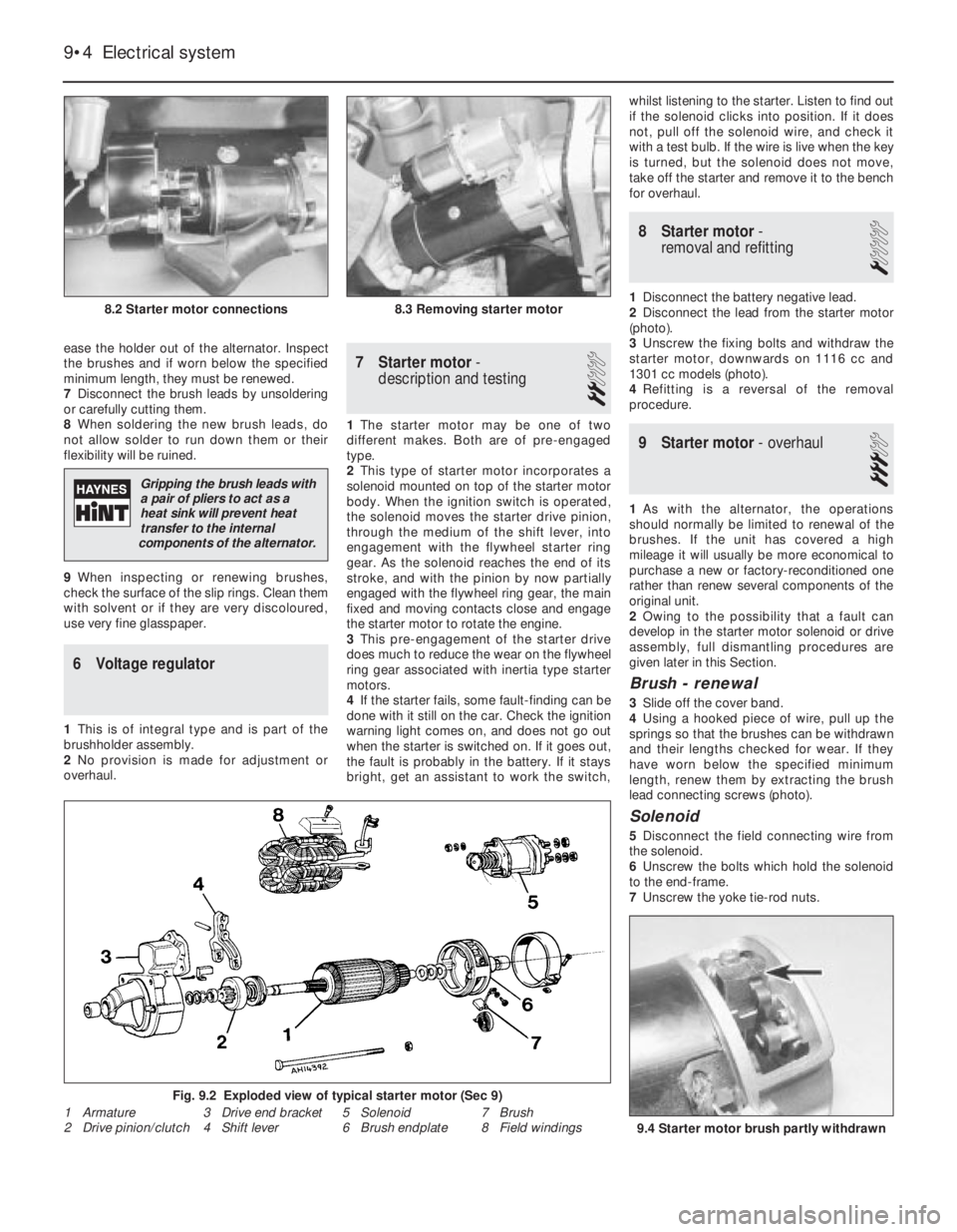
2Disconnect the lead from the starter motor
(photo).
3Unscrew the fixing bolts and withdraw the
starter motor, downwards on 1116 cc and
1301 cc models (photo).
4Refitting is a reversal of the removal
procedure.
9 Starter motor- overhaul
3
1As with the alternator, the operations
should normally be limited to renewal of the
brushes. If the unit has covered a high
mileage it will usually be more economical to
purchase a new or factory-reconditioned one
rather than renew several components of the
original unit.
2Owing to the possibility that a fault can
develop in the starter motor solenoid or drive
assembly, full dismantling procedures are
given later in this Section.
Brush - renewal
3Slide off the cover band.
4Using a hooked piece of wire, pull up the
springs so that the brushes can be withdrawn
and their lengths checked for wear. If they
have worn below the specified minimum
length, renew them by extracting the brush
lead connecting screws (photo).
Solenoid
5Disconnect the field connecting wire from
the solenoid.
6Unscrew the bolts which hold the solenoid
to the end-frame.
7Unscrew the yoke tie-rod nuts.
9•4 Electrical system
9.4 Starter motor brush partly withdrawn
8.2 Starter motor connections8.3 Removing starter motor
Fig. 9.2 Exploded view of typical starter motor (Sec 9)
1 Armature
2 Drive pinion/clutch3 Drive end bracket
4 Shift lever5 Solenoid
6 Brush endplate7 Brush
8 Field windings
Gripping the brush leads with
a pair of pliers to act as a
heat sink will prevent heat
transfer to the internal
components of the alternator.
Page 101 of 303
3The centralised door locking system can
operate independently of the key.
4To gain access to the lock solenoid and
linkage, remove the front door trim panel as
described in Chapter 12.
5Disconnect the battery negative lead.
6Disconnect the electrical wiring plugs from
the solenoid within the door cavity.
7Disconnect the solenoid from the lock lever
by removing the clip.
8Unscrew the two bolts which secure the
solenoid to the door and remove it.
9Renew the solenoid or switch as necessary.
10Refitting is a reversal of removal.
11Refer to Section 10 for details of system
fuses and relays.
33 Economy gauge
(Econometer)
2
1This device is fitted to ES (energy saving)
models and indicates to the driver the fuel
consumption (in litres per 100 km) coupled
with a needle which moves over coloured
sections of a dial to make the driver aware
that his method of driving is either conducive
to high or low fuel consumption. Refer to
Chapter 3, Section 16.
2The device is essentially a vacuum gauge
which also incorporates a warning lamp to
indicate to the driver when a change of gear is
required.
3A fuel cut-out valve (see Chapter 3, Sec-
tion 11) is used in conjunction with the
economy gauge so that when the accelerator
pedal is released during a pre-determined
engine speed range, fuel supply to the engine
is stopped, but resumes when the engine
speed falls below the specified range.
LED (light emitter diode)
4The gearchange indicator will only light up
at engine speeds in excess of 2000 rev/min
for vacuum pressures up to 600 mm Hg in 1st,
2nd and 3rd speed gears and for vacuum
pressures up to 676 mm Hg in 4th speedgear. The light will not come on if 5th speed
gear is engaged or if the coolant temperature
is below 55ºC.
5There is a two second delay in the light
coming on to prevent it operating during rapid
acceleration in a low gear.
6If the LED light comes on during
deceleration it should be ignored.
Fault finding
7A faulty economy gauge should be checked
in the following way.
8Refer to Section 21 and remove the
instrument panel.
9Disconnect the economy gauge L
connector and then connect a test lamp
between the BN cable contact and earth. If
the lamp comes on then the gauge supply
circuit is not open. If the lamp does not come
on, check all connections in the supply cable
which comes from the interconnecting unit of
the electrical system, also Fuse No 12.
10Now connect a voltmeter between the
white cable and earth. Check the voltage with
the engine not running, but the ignition
switched on. It should be between 0.7 and
0.9 volt. If the reading varies considerably
from that specified, check the connections
between the economy gauge and the fuel
cut-out device control unit. If the fault cannot
be rectified, renew the ignition control unit
(Digiplex system, see Chapter 4).
11Now check the closed throttle valve plate
switch by connecting a voltmeter between the
brown and BN cables of the L connector. With
the valve plate open, there should be no
reading, but with it open, voltage should be
indicated.
12Failure to conform as described will be
due to a faulty earth in the switch or a faulty
fuel cut-out device control unit.
13A further test of the throttle valve plate
switch may be carried out by disconnecting
the multi-plug from the fuel cut-out device
control unit.
14Connect a test lamp to contact 4 (positive
battery terminal). The lamp should come on,
when the engine is idling or the accelerator
released. If it does not, renew the throttle
valve plate switch.15Connect a tachometer to the brown/white
cable contact in the L connector and record
the engine speed with the engine running. If
no reading is obtained, renew the Digiplex
ignition control unit which must be faulty.
34 Check control (warning
module) system
2
1This is fitted into the instrument panel of
certain models to provide a means of
checking the operation of many electrical
circuits and other systems in the interest of
safety. Sensors are used where appropriate.
2The following components are not
monitored by the system, but have separate
warning lamps:
Handbrake “on”
Choke in use
Low engine oil pressure
Battery charge indicator
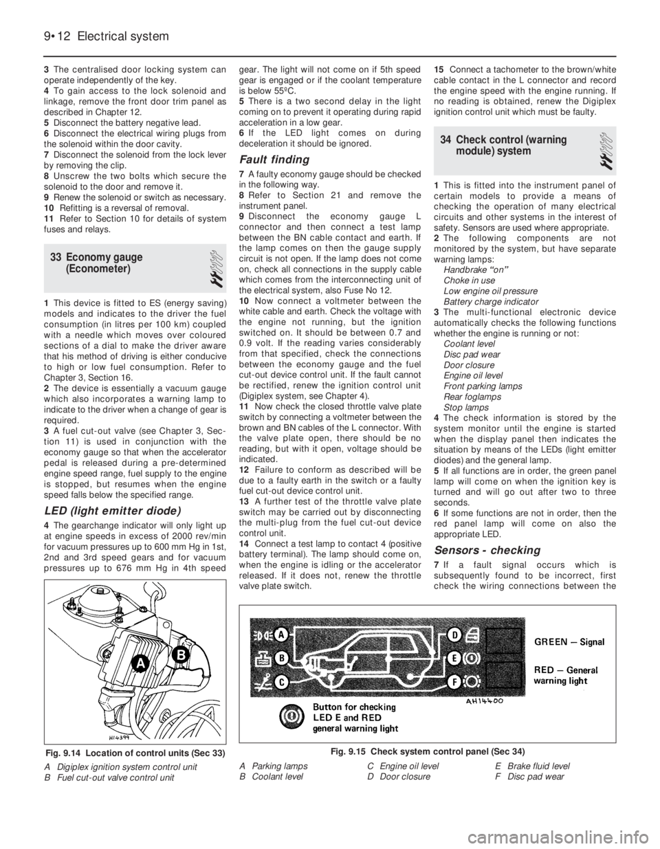
3The multi-functional electronic device
automatically checks the following functions
whether the engine is running or not:
Coolant level
Disc pad wear
Door closure
Engine oil level
Front parking lamps
Rear foglamps
Stop lamps
4The check information is stored by the
system monitor until the engine is started
when the display panel then indicates the
situation by means of the LEDs (light emitter
diodes) and the general lamp.
5If all functions are in order, the green panel
lamp will come on when the ignition key is
turned and will go out after two to three
seconds.
6If some functions are not in order, then the
red panel lamp will come on also the
appropriate LED.
Sensors - checking
7If a fault signal occurs which is
subsequently found to be incorrect, first
check the wiring connections between the
9•12 Electrical system
Fig. 9.15 Check system control panel (Sec 34)
A Parking lamps
B Coolant levelC Engine oil level
D Door closureE Brake fluid level
F Disc pad wearFig. 9.14 Location of control units (Sec 33)
A Digiplex ignition system control unit
B Fuel cut-out valve control unit