sensor FIAT UNO 1983 Service Owner's Manual
[x] Cancel search | Manufacturer: FIAT, Model Year: 1983, Model line: UNO, Model: FIAT UNO 1983Pages: 303, PDF Size: 10.36 MB
Page 161 of 303
Engine oil cooler -
removal and refittingÁ
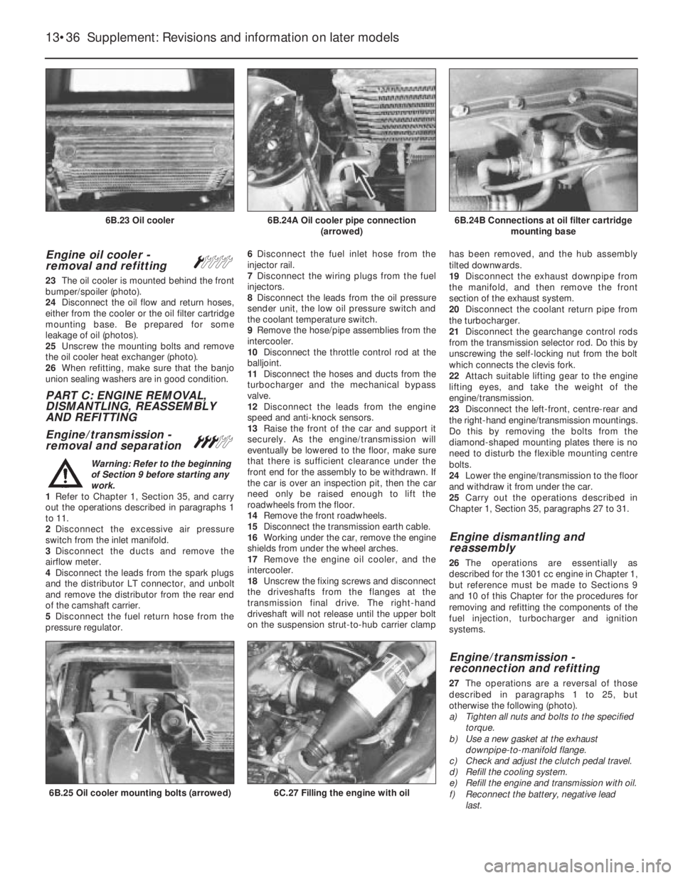
23The oil cooler is mounted behind the front
bumper/spoiler (photo).
24Disconnect the oil flow and return hoses,
either from the cooler or the oil filter cartridge
mounting base. Be prepared for some
leakage of oil (photos).
25Unscrew the mounting bolts and remove
the oil cooler heat exchanger (photo).
26When refitting, make sure that the banjo
union sealing washers are in good condition.
PART C: ENGINE REMOVAL,
DISMANTLING, REASSEMBLY
AND REFITTING
Engine/transmission -
removal and separation
#
Warning: Refer to the beginning
of Section 9 before starting any
work.
1Refer to Chapter 1, Section 35, and carry
out the operations described in paragraphs 1
to 11.
2Disconnect the excessive air pressure
switch from the inlet manifold.
3Disconnect the ducts and remove the
airflow meter.
4Disconnect the leads from the spark plugs
and the distributor LT connector, and unbolt
and remove the distributor from the rear end
of the camshaft carrier.
5Disconnect the fuel return hose from the
pressure regulator. 6Disconnect the fuel inlet hose from the
injector rail.
7Disconnect the wiring plugs from the fuel
injectors.
8Disconnect the leads from the oil pressure
sender unit, the low oil pressure switch and
the coolant temperature switch.
9Remove the hose/pipe assemblies from the
intercooler.
10Disconnect the throttle control rod at the
balljoint.
11Disconnect the hoses and ducts from the
turbocharger and the mechanical bypass
valve.
12Disconnect the leads from the engine
speed and anti-knock sensors.
13Raise the front of the car and support it
securely. As the engine/transmission will
eventually be lowered to the floor, make sure
that there is sufficient clearance under the
front end for the assembly to be withdrawn. If
the car is over an inspection pit, then the car
need only be raised enough to lift the
roadwheels from the floor.
14Remove the front roadwheels.
15Disconnect the transmission earth cable.
16Working under the car, remove the engine
shields from under the wheel arches.
17Remove the engine oil cooler, and the
intercooler.
18Unscrew the fixing screws and disconnect
the driveshafts from the flanges at the
transmission final drive. The right-hand
driveshaft will not release until the upper bolt
on the suspension strut-to-hub carrier clamphas been removed, and the hub assembly
tilted downwards.
19Disconnect the exhaust downpipe from
the manifold, and then remove the front
section of the exhaust system.
20Disconnect the coolant return pipe from
the turbocharger.
21Disconnect the gearchange control rods
from the transmission selector rod. Do this by
unscrewing the self-locking nut from the bolt
which connects the clevis fork.
22Attach suitable lifting gear to the engine
lifting eyes, and take the weight of the
engine/transmission.
23Disconnect the left-front, centre-rear and
the right-hand engine/transmission mountings.
Do this by removing the bolts from the
diamond-shaped mounting plates there is no
need to disturb the flexible mounting centre
bolts.
24Lower the engine/transmission to the floor
and withdraw it from under the car.
25Carry out the operations described in
Chapter 1, Section 35, paragraphs 27 to 31.
Engine dismantling and
reassembly
26The operations are essentially as
described for the 1301 cc engine in Chapter 1,
but reference must be made to Sections 9
and 10 of this Chapter for the procedures for
removing and refitting the components of the
fuel injection, turbocharger and ignition
systems.
Engine/transmission -
reconnection and refitting
27The operations are a reversal of those
described in paragraphs 1 to 25, but
otherwise the following (photo).
a) Tighten all nuts and bolts to the specified
torque.
b) Use a new gasket at the exhaust
downpipe-to-manifold flange.
c) Check and adjust the clutch pedal travel.
d) Refill the cooling system.
e) Refill the engine and transmission with oil.
f) Reconnect the battery, negative lead
last.
13•36 Supplement: Revisions and information on later models
6C.27 Filling the engine with oil6B.25 Oil cooler mounting bolts (arrowed)
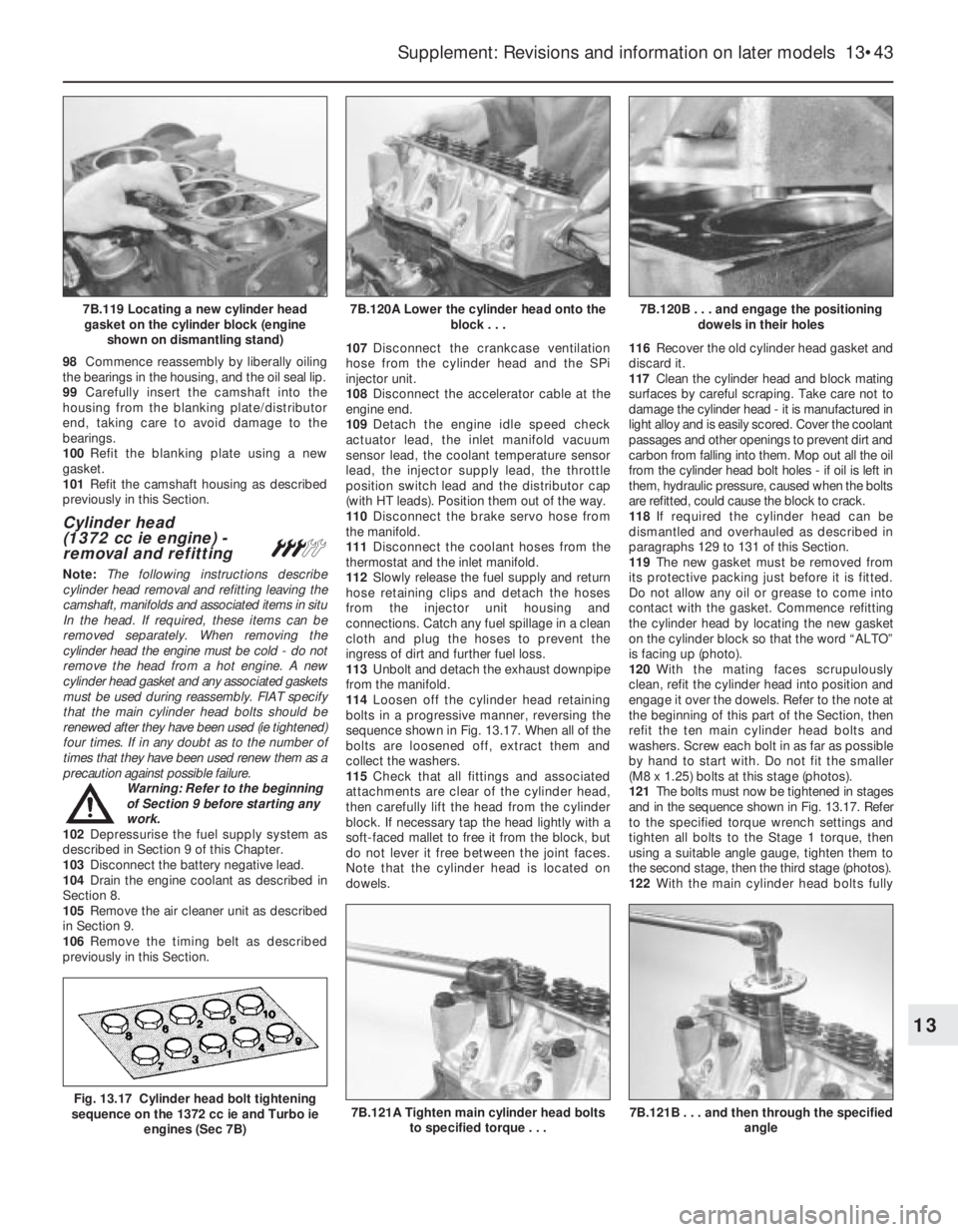
6B.24B Connections at oil filter cartridge
mounting base6B.24A Oil cooler pipe connection
(arrowed)6B.23 Oil cooler
Page 168 of 303
98Commence reassembly by liberally oiling
the bearings in the housing, and the oil seal lip.
99Carefully insert the camshaft into the
housing from the blanking plate/distributor
end, taking care to avoid damage to the
bearings.
100Refit the blanking plate using a new
gasket.
101Refit the camshaft housing as described
previously in this Section.
Cylinder head
(1372 cc ie engine) -
removal and refitting
#
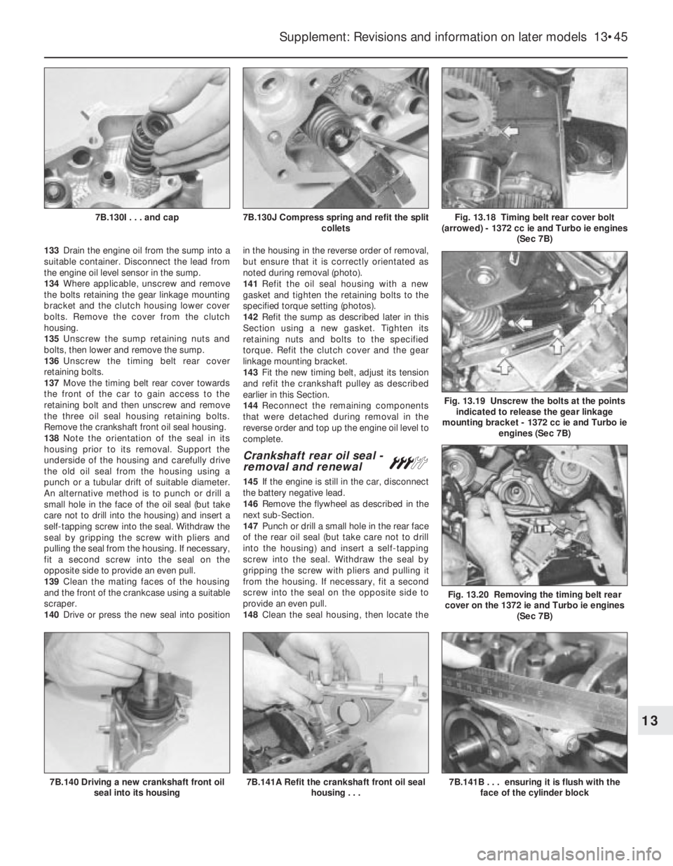
Note: The following instructions describe
cylinder head removal and refitting leaving the
camshaft, manifolds and associated items in situ
In the head. If required, these items can be
removed separately. When removing the
cylinder head the engine must be cold - do not
remove the head from a hot engine. A new
cylinder head gasket and any associated gaskets
must be used during reassembly. FIAT specify
that the main cylinder head bolts should be
renewed after they have been used (ie tightened)
four times. If in any doubt as to the number of
times that they have been used renew them as a
precaution against possible failure.
Warning: Refer to the beginning
of Section 9 before starting any
work.
102Depressurise the fuel supply system as
described in Section 9 of this Chapter.
103Disconnect the battery negative lead.
104Drain the engine coolant as described in
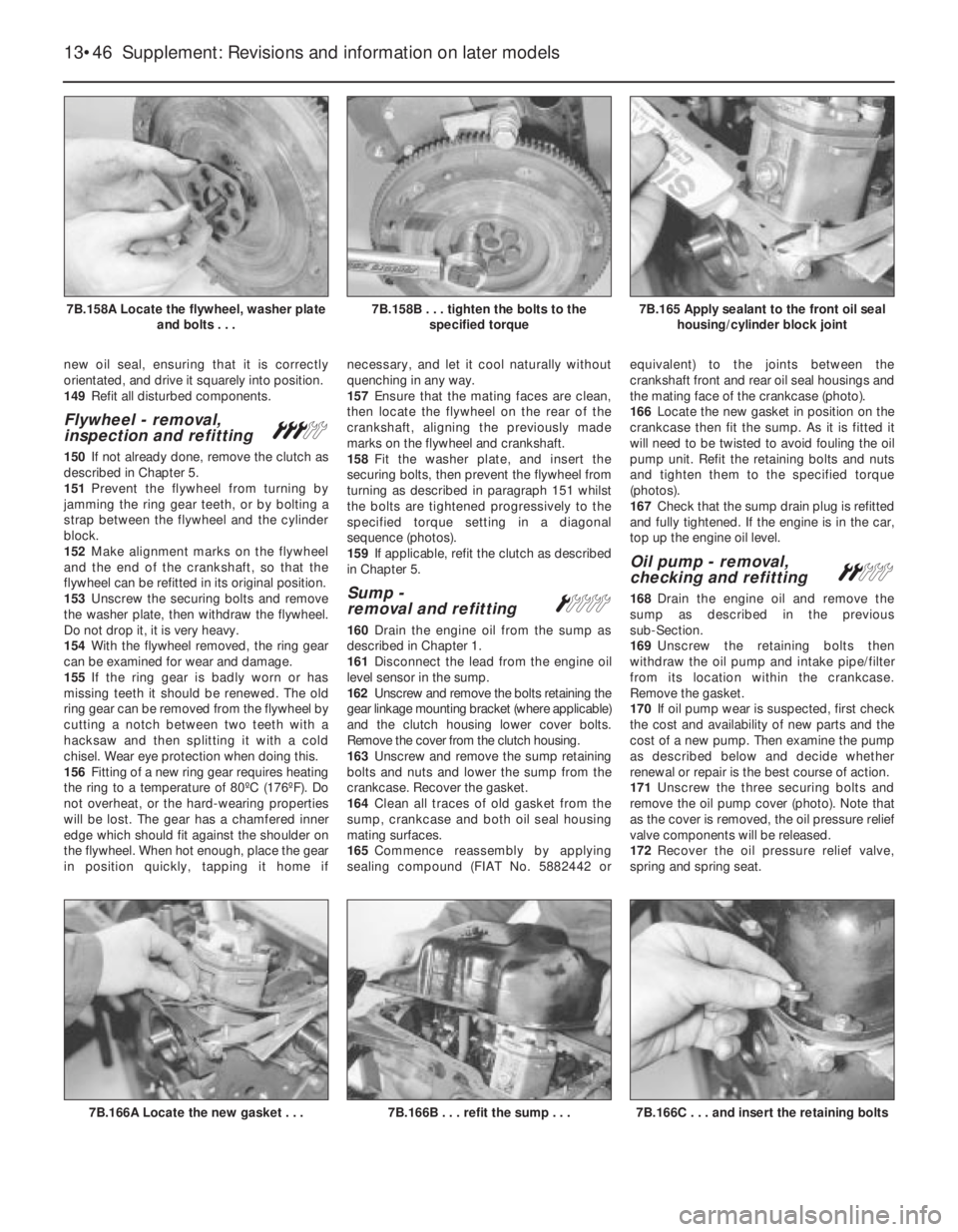
Section 8.
105Remove the air cleaner unit as described
in Section 9.
106Remove the timing belt as described
previously in this Section.107Disconnect the crankcase ventilation
hose from the cylinder head and the SPi
injector unit.
108Disconnect the accelerator cable at the
engine end.
109Detach the engine idle speed check
actuator lead, the inlet manifold vacuum
sensor lead, the coolant temperature sensor
lead, the injector supply lead, the throttle
position switch lead and the distributor cap
(with HT leads). Position them out of the way.
110Disconnect the brake servo hose from
the manifold.
111Disconnect the coolant hoses from the
thermostat and the inlet manifold.
112Slowly release the fuel supply and return
hose retaining clips and detach the hoses
from the injector unit housing and
connections. Catch any fuel spillage in a clean
cloth and plug the hoses to prevent the
ingress of dirt and further fuel loss.
113Unbolt and detach the exhaust downpipe
from the manifold.
114Loosen off the cylinder head retaining
bolts in a progressive manner, reversing the
sequence shown in Fig. 13.17. When all of the
bolts are loosened off, extract them and
collect the washers.
115Check that all fittings and associated
attachments are clear of the cylinder head,
then carefully lift the head from the cylinder
block. If necessary tap the head lightly with a
soft-faced mallet to free it from the block, but
do not lever it free between the joint faces.
Note that the cylinder head is located on
dowels.116Recover the old cylinder head gasket and
discard it.
117Clean the cylinder head and block mating
surfaces by careful scraping. Take care not to
damage the cylinder head - it is manufactured in
light alloy and is easily scored. Cover the coolant
passages and other openings to prevent dirt and
carbon from falling into them. Mop out all the oil
from the cylinder head bolt holes - if oil is left in
them, hydraulic pressure, caused when the bolts
are refitted, could cause the block to crack.
118If required the cylinder head can be
dismantled and overhauled as described in
paragraphs 129 to 131 of this Section.
119The new gasket must be removed from
its protective packing just before it is fitted.
Do not allow any oil or grease to come into
contact with the gasket. Commence refitting
the cylinder head by locating the new gasket
on the cylinder block so that the word “ALTO”
is facing up (photo).
120With the mating faces scrupulously
clean, refit the cylinder head into position and
engage it over the dowels. Refer to the note at
the beginning of this part of the Section, then
refit the ten main cylinder head bolts and
washers. Screw each bolt in as far as possible
by hand to start with. Do not fit the smaller
(M8 x 1.25) bolts at this stage (photos).
121The bolts must now be tightened in stages
and in the sequence shown in Fig. 13.17. Refer
to the specified torque wrench settings and
tighten all bolts to the Stage 1 torque, then
using a suitable angle gauge, tighten them to
the second stage, then the third stage (photos).
122With the main cylinder head bolts fully
Supplement: Revisions and information on later models 13•43
7B.120B . . . and engage the positioning
dowels in their holes7B.120A Lower the cylinder head onto the
block . . .7B.119 Locating a new cylinder head
gasket on the cylinder block (engine
shown on dismantling stand)
7B.121A Tighten main cylinder head bolts
to specified torque . . .Fig. 13.17 Cylinder head bolt tightening
sequence on the 1372 cc ie and Turbo ie
engines (Sec 7B)
13
7B.121B . . . and then through the specified
angle
Page 170 of 303
133Drain the engine oil from the sump into a
suitable container. Disconnect the lead from
the engine oil level sensor in the sump.
134Where applicable, unscrew and remove
the bolts retaining the gear linkage mounting
bracket and the clutch housing lower cover
bolts. Remove the cover from the clutch
housing.
135Unscrew the sump retaining nuts and
bolts, then lower and remove the sump.
136Unscrew the timing belt rear cover
retaining bolts.
137Move the timing belt rear cover towards
the front of the car to gain access to the
retaining bolt and then unscrew and remove
the three oil seal housing retaining bolts.
Remove the crankshaft front oil seal housing.
138Note the orientation of the seal in its
housing prior to its removal. Support the
underside of the housing and carefully drive
the old oil seal from the housing using a
punch or a tubular drift of suitable diameter.
An alternative method is to punch or drill a
small hole in the face of the oil seal (but take
care not to drill into the housing) and insert a
self-tapping screw into the seal. Withdraw the
seal by gripping the screw with pliers and
pulling the seal from the housing. If necessary,
fit a second screw into the seal on the
opposite side to provide an even pull.
139Clean the mating faces of the housing
and the front of the crankcase using a suitable
scraper.
140Drive or press the new seal into positionin the housing in the reverse order of removal,
but ensure that it is correctly orientated as
noted during removal (photo).
141Refit the oil seal housing with a new
gasket and tighten the retaining bolts to the
specified torque setting (photos).
142Refit the sump as described later in this
Section using a new gasket. Tighten its
retaining nuts and bolts to the specified
torque. Refit the clutch cover and the gear
linkage mounting bracket.
143Fit the new timing belt, adjust its tension
and refit the crankshaft pulley as described
earlier in this Section.
144Reconnect the remaining components
that were detached during removal in the
reverse order and top up the engine oil level to
complete.
Crankshaft rear oil seal -
removal and renewal#
145If the engine is still in the car, disconnect
the battery negative lead.
146Remove the flywheel as described in the
next sub-Section.
147Punch or drill a small hole in the rear face
of the rear oil seal (but take care not to drill
into the housing) and insert a self-tapping
screw into the seal. Withdraw the seal by
gripping the screw with pliers and pulling it
from the housing. If necessary, fit a second
screw into the seal on the opposite side to
provide an even pull.
148Clean the seal housing, then locate the
Supplement: Revisions and information on later models 13•45
Fig. 13.18 Timing belt rear cover bolt
(arrowed) - 1372 cc ie and Turbo ie engines
(Sec 7B)7B.130J Compress spring and refit the split
collets7B.130I . . . and cap
7B.140 Driving a new crankshaft front oil
seal into its housing7B.141B . . . ensuring it is flush with the
face of the cylinder block7B.141A Refit the crankshaft front oil seal
housing . . .
Fig. 13.20 Removing the timing belt rear
cover on the 1372 ie and Turbo ie engines
(Sec 7B)
Fig. 13.19 Unscrew the bolts at the points
indicated to release the gear linkage
mounting bracket - 1372 cc ie and Turbo ie
engines (Sec 7B)
13
Page 171 of 303
new oil seal, ensuring that it is correctly
orientated, and drive it squarely into position.
149Refit all disturbed components.
Flywheel - removal,
inspection and refitting#
150If not already done, remove the clutch as
described in Chapter 5.
151Prevent the flywheel from turning by
jamming the ring gear teeth, or by bolting a
strap between the flywheel and the cylinder
block.
152Make alignment marks on the flywheel
and the end of the crankshaft, so that the
flywheel can be refitted in its original position.
153Unscrew the securing bolts and remove
the washer plate, then withdraw the flywheel.
Do not drop it, it is very heavy.
154With the flywheel removed, the ring gear
can be examined for wear and damage.
155If the ring gear is badly worn or has
missing teeth it should be renewed. The old
ring gear can be removed from the flywheel by
cutting a notch between two teeth with a
hacksaw and then splitting it with a cold
chisel. Wear eye protection when doing this.
156Fitting of a new ring gear requires heating
the ring to a temperature of 80ºC (176ºF). Do
not overheat, or the hard-wearing properties
will be lost. The gear has a chamfered inner
edge which should fit against the shoulder on
the flywheel. When hot enough, place the gear
in position quickly, tapping it home ifnecessary, and let it cool naturally without
quenching in any way.
157Ensure that the mating faces are clean,
then locate the flywheel on the rear of the
crankshaft, aligning the previously made
marks on the flywheel and crankshaft.
158Fit the washer plate, and insert the
securing bolts, then prevent the flywheel from
turning as described in paragraph 151 whilst
the bolts are tightened progressively to the
specified torque setting in a diagonal
sequence (photos).
159If applicable, refit the clutch as described
in Chapter 5.
Sump -
removal and refittingÁ
160Drain the engine oil from the sump as
described in Chapter 1.
161Disconnect the lead from the engine oil
level sensor in the sump.
162Unscrew and remove the bolts retaining the
gear linkage mounting bracket (where applicable)
and the clutch housing lower cover bolts.
Remove the cover from the clutch housing.
163Unscrew and remove the sump retaining
bolts and nuts and lower the sump from the
crankcase. Recover the gasket.
164Clean all traces of old gasket from the
sump, crankcase and both oil seal housing
mating surfaces.
165Commence reassembly by applying
sealing compound (FIAT No. 5882442 orequivalent) to the joints between the
crankshaft front and rear oil seal housings and
the mating face of the crankcase (photo).
166Locate the new gasket in position on the
crankcase then fit the sump. As it is fitted it
will need to be twisted to avoid fouling the oil
pump unit. Refit the retaining bolts and nuts
and tighten them to the specified torque
(photos).
167Check that the sump drain plug is refitted
and fully tightened. If the engine is in the car,
top up the engine oil level.
Oil pump - removal,
checking and refittingª
168Drain the engine oil and remove the
sump as described in the previous
sub-Section.
169Unscrew the retaining bolts then
withdraw the oil pump and intake pipe/filter
from its location within the crankcase.
Remove the gasket.
170If oil pump wear is suspected, first check
the cost and availability of new parts and the
cost of a new pump. Then examine the pump
as described below and decide whether
renewal or repair is the best course of action.
171Unscrew the three securing bolts and
remove the oil pump cover (photo). Note that
as the cover is removed, the oil pressure relief
valve components will be released.
172Recover the oil pressure relief valve,
spring and spring seat.
13•46 Supplement: Revisions and information on later models
7B.166C . . . and insert the retaining bolts7B.166B . . . refit the sump . . .7B.166A Locate the new gasket . . .
7B.165 Apply sealant to the front oil seal
housing/cylinder block joint7B.158B . . . tighten the bolts to the
specified torque7B.158A Locate the flywheel, washer plate
and bolts . . .
Page 174 of 303
fitting, as during removal. Note that the
compression rings are brittle, and will snap if
expanded too far.
206If new pistons are to be fitted, they must
be selected from the grades available, after
measuring the cylinder bores. Normally, the
appropriate oversize pistons are supplied by
the dealer when the block is rebored.
207Whenever new piston rings are being
installed, the glaze on the original cylinder
bores should be removed using either
abrasive paper or a glaze-removing tool in an
electric drill. If abrasive paper is used, use
strokes at 60º to the bore centre-line, to
create a cross-hatching effect.
Engine/transmission
mountings - renewalÁ
208The engine/gearbox assembly is
suspended in the engine compartment on
three mountings, two of which are attached to
the gearbox, and one to the engine.
Right-hand mounting
209Apply the handbrake, then jack up the
front of the vehicle and support it securely on
axle stands.
210Suitable lifting tackle must now be
attached to the engine in order to support it as
the engine mounting is removed. No lifting
brackets are provided, so care must be taken
when deciding on an engine lifting point. In the
workshop, a right-angled bracket was made up
by bending a suitable piece of steel plate. The
bracket was then bolted to the engine using the
rear right-hand camshaft housing securing bolt
with suitable packing washers.
211Attach the lifting tackle to the bracket on
the engine and just take the weight of the
assembly.
212Working under the vehicle, unbolt the
engine mounting bracket from the cylinder
block, and unbolt the mounting from the
body, then withdraw the bracket/mounting
assembly.
213Unscrew the nut and through-bolt,
counter holding the bolt with a second
spanner or socket, and separate the mounting
from the bracket.
214Fit the new mounting to the bracket, and
tighten the nut to the specified torque, while
counterholding the through-bolt using a
suitable spanner or socket.
215Refit the mounting bracket to the cylinder
block, and tighten the securing bolts to the
specified torque.
216Refit the mounting to the body and
tighten the securing bolts to the specified
torque.
217Disconnect the lifting tackle from the
engine, and remove the engine lifting bracket.
218Lower the vehicle to the ground.
Left-hand mountings
219Apply the handbrake, then jack up the
front of the vehicle and support it securely on
axle stands.
220Suitable lifting tackle must now be
attached to the gearbox lifting bracket inorder to support the weight of the assembly
as the mounting is removed.
221Attach the lifting tackle to the bracket on
the gearbox, and just take the weight of the
assembly.
222Working under the vehicle, unbolt the
mounting bracket from the gearbox, and
unbolt the mounting from the body, then
withdraw the bracket/mounting assembly.
223Proceed as described in paragraphs 213
and 214.
224Refit the mounting bracket to the
gearbox, and tighten the securing bolts to the
specified torque.
225Refit the mounting to the body and
tighten the mounting bolts to the specified
torque.
226Disconnect the lifting tackle from the
engine.
227Lower the vehicle to the ground.
PART C: ENGINE REMOVAL
AND DISMANTLING
Method of removal - general
1The engine (complete with transmission) is
disconnected and lowered downwards
through the engine compartment, then
withdrawn from the front underside of the car.
1372 cc engine/
transmission - removal
and separation
#
Warning: Refer to the beginning
of Section 9 before starting any
work.
2Depressurize the fuel system as described
in Section 9 of this Chapter.
3Disconnect the battery negative lead.
4Mark the position of the hinges on the
underside of the bonnet, then with the aid of
an assistant, unscrew the hinge bolts and lift
the bonnet clear of the car. Store the bonnet
in a safe area.
5Drain the engine coolant.
6Drain the engine and transmission oils.
7Disconnect and remove the air filter.
8Disconnect the coolant hoses from the
engine, including the hose to the inlet
manifold.
9Detach the ignition coil (HT) lead from the
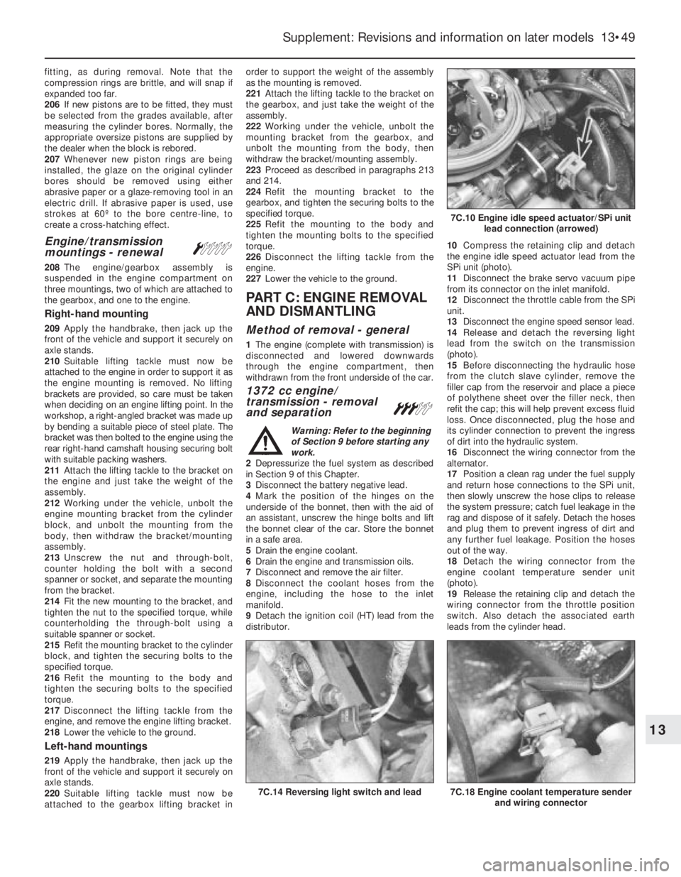
distributor.10Compress the retaining clip and detach
the engine idle speed actuator lead from the
SPi unit (photo).
11Disconnect the brake servo vacuum pipe
from its connector on the inlet manifold.
12Disconnect the throttle cable from the SPi
unit.
13Disconnect the engine speed sensor lead.
14Release and detach the reversing light
lead from the switch on the transmission
(photo).
15Before disconnecting the hydraulic hose
from the clutch slave cylinder, remove the
filler cap from the reservoir and place a piece
of polythene sheet over the filler neck, then
refit the cap; this will help prevent excess fluid
loss. Once disconnected, plug the hose and
its cylinder connection to prevent the ingress
of dirt into the hydraulic system.
16Disconnect the wiring connector from the
alternator.
17Position a clean rag under the fuel supply
and return hose connections to the SPi unit,
then slowly unscrew the hose clips to release
the system pressure; catch fuel leakage in the
rag and dispose of it safely. Detach the hoses
and plug them to prevent ingress of dirt and
any further fuel leakage. Position the hoses
out of the way.
18Detach the wiring connector from the
engine coolant temperature sender unit
(photo).
19Release the retaining clip and detach the
wiring connector from the throttle position
switch. Also detach the associated earth
leads from the cylinder head.
Supplement: Revisions and information on later models 13•49
7C.14 Reversing light switch and lead7C.18 Engine coolant temperature sender
and wiring connector
7C.10 Engine idle speed actuator/SPi unit
lead connection (arrowed)
13
Page 175 of 303
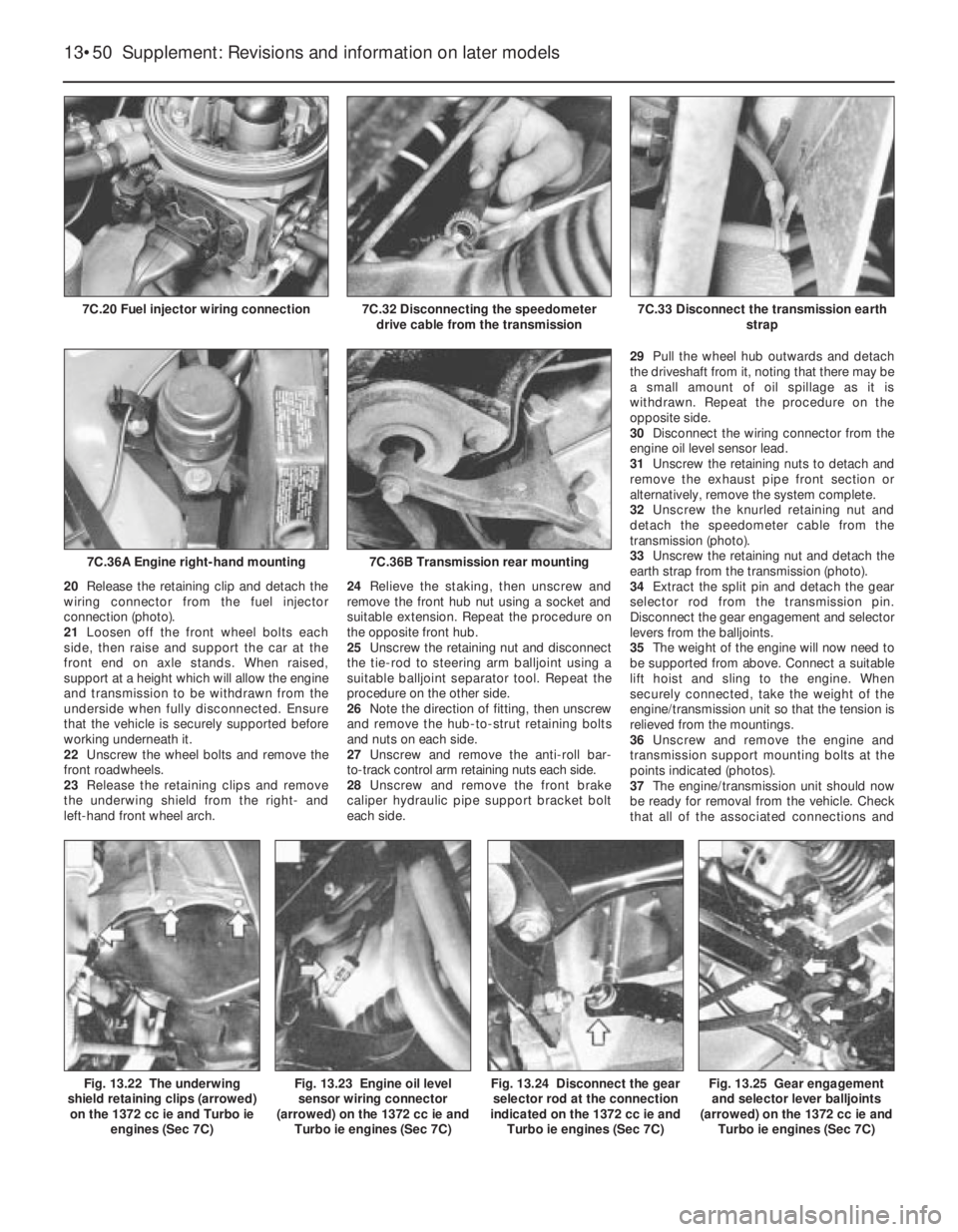
20Release the retaining clip and detach the
wiring connector from the fuel injector
connection (photo).
21Loosen off the front wheel bolts each
side, then raise and support the car at the
front end on axle stands. When raised,
support at a height which will allow the engine
and transmission to be withdrawn from the
underside when fully disconnected. Ensure
that the vehicle is securely supported before
working underneath it.
22Unscrew the wheel bolts and remove the
front roadwheels.
23Release the retaining clips and remove
the underwing shield from the right- and
left-hand front wheel arch.24Relieve the staking, then unscrew and
remove the front hub nut using a socket and
suitable extension. Repeat the procedure on
the opposite front hub.
25Unscrew the retaining nut and disconnect
the tie-rod to steering arm balljoint using a
suitable balljoint separator tool. Repeat the
procedure on the other side.
26Note the direction of fitting, then unscrew
and remove the hub-to-strut retaining bolts
and nuts on each side.
27Unscrew and remove the anti-roll bar-
to-track control arm retaining nuts each side.
28Unscrew and remove the front brake
caliper hydraulic pipe support bracket bolt
each side.29Pull the wheel hub outwards and detach
the driveshaft from it, noting that there may be
a small amount of oil spillage as it is
withdrawn. Repeat the procedure on the
opposite side.
30Disconnect the wiring connector from the
engine oil level sensor lead.
31Unscrew the retaining nuts to detach and
remove the exhaust pipe front section or
alternatively, remove the system complete.
32Unscrew the knurled retaining nut and
detach the speedometer cable from the
transmission (photo).
33Unscrew the retaining nut and detach the
earth strap from the transmission (photo).
34Extract the split pin and detach the gear
selector rod from the transmission pin.
Disconnect the gear engagement and selector
levers from the balljoints.
35The weight of the engine will now need to
be supported from above. Connect a suitable
lift hoist and sling to the engine. When
securely connected, take the weight of the
engine/transmission unit so that the tension is
relieved from the mountings.
36Unscrew and remove the engine and
transmission support mounting bolts at the
points indicated (photos).
37The engine/transmission unit should now
be ready for removal from the vehicle. Check
that all of the associated connections and
13•50 Supplement: Revisions and information on later models
Fig. 13.22 The underwing
shield retaining clips (arrowed)
on the 1372 cc ie and Turbo ie
engines (Sec 7C)Fig. 13.25 Gear engagement
and selector lever balljoints
(arrowed) on the 1372 cc ie and
Turbo ie engines (Sec 7C)Fig. 13.23 Engine oil level
sensor wiring connector
(arrowed) on the 1372 cc ie and
Turbo ie engines (Sec 7C)Fig. 13.24 Disconnect the gear
selector rod at the connection
indicated on the 1372 cc ie and
Turbo ie engines (Sec 7C)
7C.33 Disconnect the transmission earth
strap7C.32 Disconnecting the speedometer
drive cable from the transmission7C.20 Fuel injector wiring connection
7C.36B Transmission rear mounting7C.36A Engine right-hand mounting
Page 192 of 303
solenoid-operated type, actuated from the
ECU.
7Fuel pressure is regulated according to inlet
manifold vacuum pressure by a fuel pressure
regulator. Excess unpressurised fuel is
returned to the fuel tank.
Airflow meter
8This component measures the quantity of
air drawn into the engine, and converts this
into an electric signal which is transmitted to
the ECU.
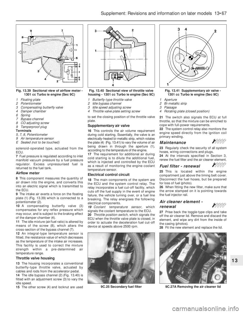
9The intake air exerts a force on the floating
plate (1) (Fig. 13.39) which is connected to a
potentiometer (2).
10A compensating butterfly valve (3)
compensates for any reflex pressure which
may occur, and is subject to the braking effect
of the damper chamber (4).
11The idle mixture (air/fuel ratio) is altered by
means of the screw (8), which alters the
cross-section of the bypass channel (7).
12An integral-type temperature sensor is
fitted, the resistance value of which decreases
as the temperature of the intake air increases.
This facility is used to correct the mixture
strength within a pre-determined air
temperature range.
Throttle valve housing
13The housing incorporates a conventional
butterfly-type throttle valve, actuated by
cables and rods from the accelerator pedal.
14The idle bypass channel (2) (Fig. 13.40) is
fitted with an adjustment screw (3) to vary the
idle speed.
15The other screw (4) and locknut are usedto set the closing position of the throttle valve
plate.
Supplementary air valve
16This controls the air volume requirement
during cold starting. Essentially, the valve is an
electrically-heated bi-metallic strip, which rotates
the plate (4) (Fig. 13.41) to vary the volume of air
being drawn in through the aperture (1),
according to the temperature of the engine.
17The requirement for additional air during
cold starting is to dilute the additional fuel,
which is injected and controlled by the ECU
as a result of monitoring the engine coolant
temperature sensor.
Electrical control circuit
18The main components of the system are
the ECU and the system control relay. The
relay incorporates a fuel cut-off facility, which
cuts off the fuel supply in the event of engine
failure, the vehicle turning over, or a fuel line
breaking. The relay energises the following
electrical components.
19Coolant temperature sensor, which
signals the coolant temperature to the ECU.
20Throttle position switch, which signals the
ECU when the throttle valve plate is closed, in
order to actuate the deceleration fuel cut-off
device at speeds above 2500 rpm.21The switch also signals the ECU at full
throttle, so that the mixture can be enriched to
cope with full-power requirements.
22The system control relay also monitors the
engine speed directly from the ignition coil
primary winding.
MaintenanceÁ
23Regularly check the security of all system
hoses, wiring connections and plugs.
24At the intervals specified in Section 3,
renew the fuel filter and the air cleaner element.
Fuel filter - renewalÁ
25This is located within the engine
compartment just above the timing belt cover.
Disconnect the fuel hoses, but be prepared
for loss of fuel (photo).
26When fitting the new filter, make sure that
the arrow stamped on it is pointing towards
the fuel injector rail.
Air cleaner element -
renewal
Á
27Prise back the toggle-type clips and take
off the air cleaner lid. Remove and discard the
element, and wipe any dirt from the inside of
the casing (photos).
28Fit the new element and replace the lid.
Supplement: Revisions and information on later models 13•67
Fig. 13.41 Supplementary air valve -
1301 cc Turbo ie engine (Sec 9C)
1 Aperture
2 Bi-metallic strip
3 Passage
4 Rotating plate (closed position)Fig. 13.40 Sectional view of throttle valve
housing - 1301 cc Turbo ie engine (Sec 9C)
1 Butterfly-type throttle valve
2 Idle bypass channel
3 Idle speed adjusting screw
4 Throttle valve plate setting screwFig. 13.39 Sectional view of airflow meter -
1301 cc Turbo ie engine (Sec 9C)
1 Floating plate
2 Potentiometer
3 Compensating butterfly valve
4 Damper chamber
6 Spring
7 Bypass channel
8 CO adjusting screw
9 Tamperproof plug
Terminals
5, 7, 8, Potentiometer
9 Air temperature sensor
E Sealed (not to be touched)
9C.27A Removing the air cleaner lid9C.25 Secondary fuel filter
13
Page 193 of 303
Idle speed and mixture
adjustment¢
29Before carrying out any adjustments, the
engine must be at operating temperature, the
fan having cut in at second speed and then
switched off.
30Release the locknut and turn the main idle
speed screw in the throttle valve housing until
the engine idles at the specified speed. This
should be all that is necessary to obtain the
correct idle speed, as the throttle valve plate
base setting is set during production.
However, if wear has taken place, or incorrect
adjustment has been carried out previously,
proceed in the following way.
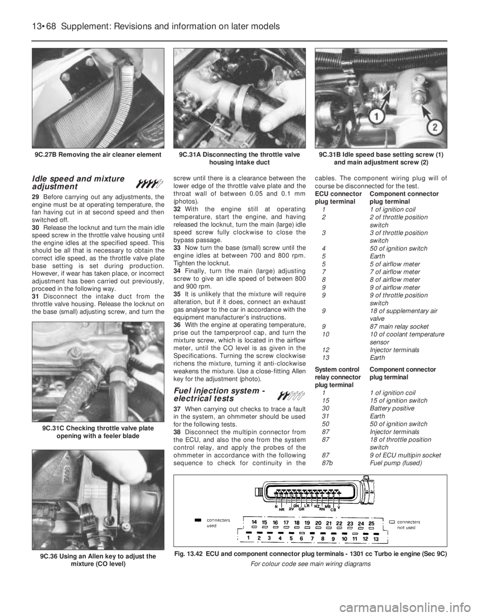
31Disconnect the intake duct from the
throttle valve housing. Release the locknut on
the base (small) adjusting screw, and turn thescrew until there is a clearance between the
lower edge of the throttle valve plate and the
throat wall of between 0.05 and 0.1 mm
(photos).
32With the engine still at operating
temperature, start the engine, and having
released the locknut, turn the main (large) idle
speed screw fully clockwise to close the
bypass passage.
33Now turn the base (small) screw until the
engine idles at between 700 and 800 rpm.
Tighten the locknut.
34Finally, turn the main (large) adjusting
screw to give an idle speed of between 800
and 900 rpm.
35It is unlikely that the mixture will require
alteration, but if it does, connect an exhaust
gas analyser to the car in accordance with the
equipment manufacturer’s instructions.
36With the engine at operating temperature,
prise out the tamperproof cap, and turn the
mixture screw, which is located in the airflow
meter, until the CO level is as given in the
Specifications. Turning the screw clockwise
richens the mixture, turning it anti-clockwise
weakens the mixture. Use a close-fitting Allen
key for the adjustment (photo).
Fuel injection system -
electrical testsª
37When carrying out checks to trace a fault
in the system, an ohmmeter should be used
for the following tests.
38Disconnect the multipin connector from
the ECU, and also the one from the system
control relay, and apply the probes of the
ohmmeter in accordance with the following
sequence to check for continuity in thecables. The component wiring plug will of
course be disconnected for the test.
ECU connector Component connector
plug terminal plug terminal
1 1 of ignition coil
2 2 of throttle position
switch
3 3 of throttle position
switch
4 50 of ignition switch
5 Earth
5 5 of airflow meter
7 7 of airflow meter
8 8 of airflow meter
9 9 of airflow meter
9 9 of throttle position
switch
9 18 of supplementary air
valve
9 87 main relay socket
10 10 of coolant temperature
sensor
12 Injector terminals
13 Earth
System control Component connector
relay connector plug terminal
plug terminal
1 1 of ignition coil
15 15 of ignition switch
30 Battery positive
31 Earth
50 50 of ignition switch
87 Injector terminals
87 18 of throttle position
switch
87 9 of ECU multipin socket
87b Fuel pump (fused)
13•68 Supplement: Revisions and information on later models
Fig. 13.42 ECU and component connector plug terminals - 1301 cc Turbo ie engine (Sec 9C)
For colour code see main wiring diagrams
9C.31C Checking throttle valve plate
opening with a feeler blade
9C.36 Using an Allen key to adjust the
mixture (CO level)
9C.31B Idle speed base setting screw (1)
and main adjustment screw (2)9C.31A Disconnecting the throttle valve
housing intake duct9C.27B Removing the air cleaner element
Page 194 of 303
39Now use the ohmmeter to check the
resistance of the following components.
Supplementary air valve
40Resistance between the terminals should
be between 40 and 60 ohms at 20ºC (68ºF).
Airflow meter
41Resistance between terminals 5 and 8 of
the potentiometer should be between 330 and
360 ohms at 20ºC (68ºF).
42Resistance between terminals 8 and 9 of
the internal circuit should be between 190 and
210 ohms at 20ºC (68ºF) and between 170
and 190 ohms at 60ºC (140ºF).
Coolant temperature sensor
43At 20ºC (68ºF) the resistance should be
between 2 and 4 k ohms. At 50ºC (122ºF) the
resistance should be between 600 and
900 ohms. At 90ºC (194ºF) the resistance
should be between 100 and 300 ohms.
Fuel injectors
44The winding resistance should be
between 15 and 17 ohms at 20ºC (68ºF).
Throttle position switch
45With the throttle butterfly valve closed,
there should be continuity between ter-
minals 18 and 2, and with the valve fully open,
there should be no continuity between
terminals 18 and 3.
46The throttle position switch should not be
disturbed unless absolutely necessary. If it
has to be removed, then refit it so that themicroswitch is heard to click immediately the
throttle butterfly is opened.
Fuel injection system -
mechanical tests ª
Fuel pump
47To test the pressure of the fuel pump, a
pressure gauge will be required, connected
into the fuel delivery hose.
48Remove the multipin plug from the system
control relay and bridge terminals 87b and 30.
49Turn the ignition switch on. The pump
should operate and indicate a pressure of
between 2.8 and 3.0 bars (40 and 44 lbf/in
2).
50To check the operation of the peak
pressure regulator, pinch the fuel return hose.
If the fuel pressure increases, the regulator
must be faulty, and should be renewed.
51Check that the fuel pressure increases
when, with the engine idling, the accelerator is
depressed sharply.
Supplementary air valve
52With the engine at normal operating
temperature and idling, pinch the
supplementary air valve hose using a pair of
pliers. The engine speed should not drop by
more than 50 rpm. If it does, renew the valve.
Fuel injection system
components -
removal and refitting
ª
53Disconnect the battery before carrying out
any of the following operations.
Air cleaner
54Remove the cover and filter element as
previously described.
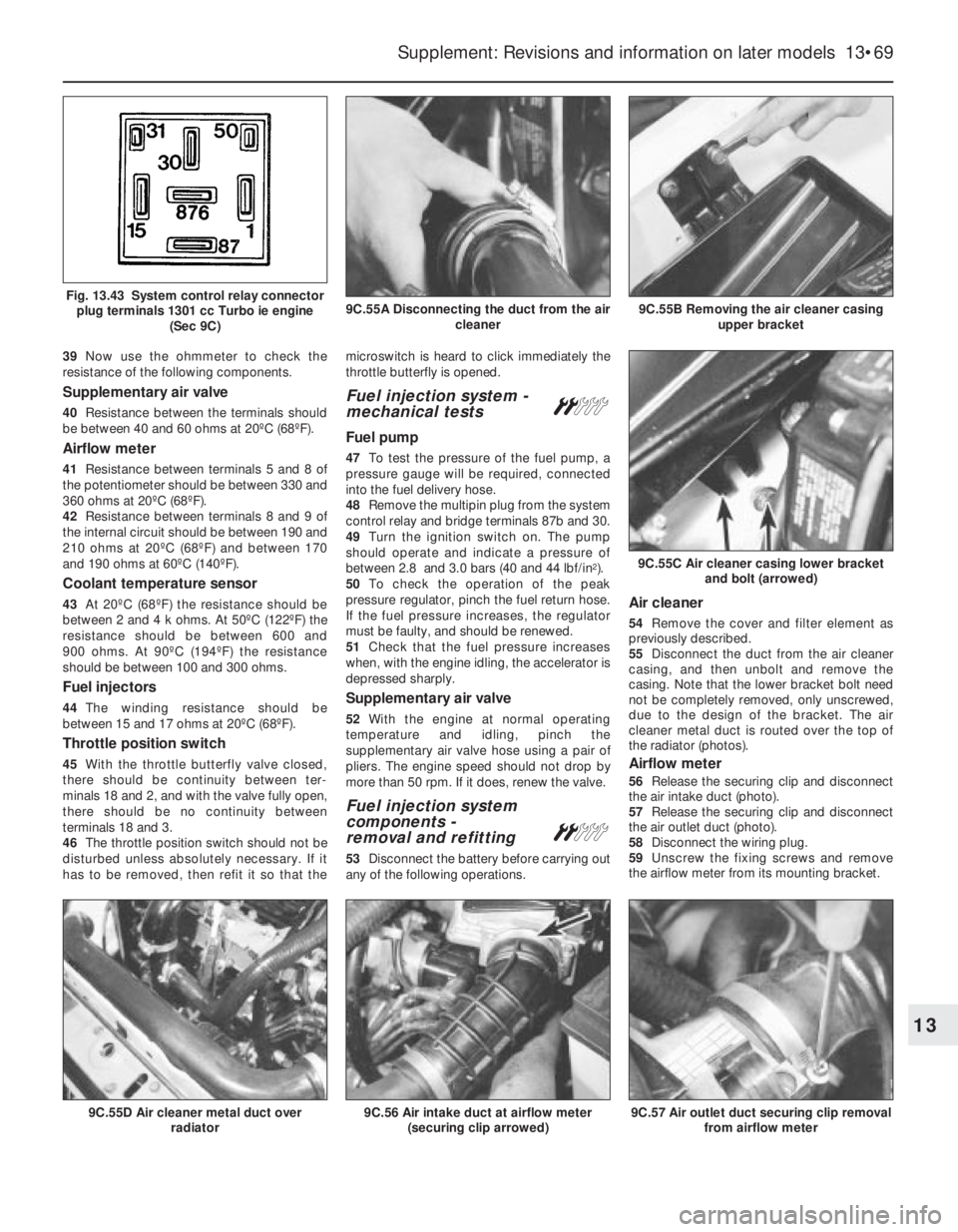
55Disconnect the duct from the air cleaner
casing, and then unbolt and remove the
casing. Note that the lower bracket bolt need
not be completely removed, only unscrewed,
due to the design of the bracket. The air
cleaner metal duct is routed over the top of
the radiator (photos).
Airflow meter
56Release the securing clip and disconnect
the air intake duct (photo).
57Release the securing clip and disconnect
the air outlet duct (photo).
58Disconnect the wiring plug.
59Unscrew the fixing screws and remove
the airflow meter from its mounting bracket.
Supplement: Revisions and information on later models 13•69
9C.55B Removing the air cleaner casing
upper bracket9C.55A Disconnecting the duct from the air
cleanerFig. 13.43 System control relay connector
plug terminals 1301 cc Turbo ie engine
(Sec 9C)
9C.57 Air outlet duct securing clip removal
from airflow meter
9C.55C Air cleaner casing lower bracket
and bolt (arrowed)
9C.56 Air intake duct at airflow meter
(securing clip arrowed)9C.55D Air cleaner metal duct over
radiator
13
Page 195 of 303
Fuel pressure regulator
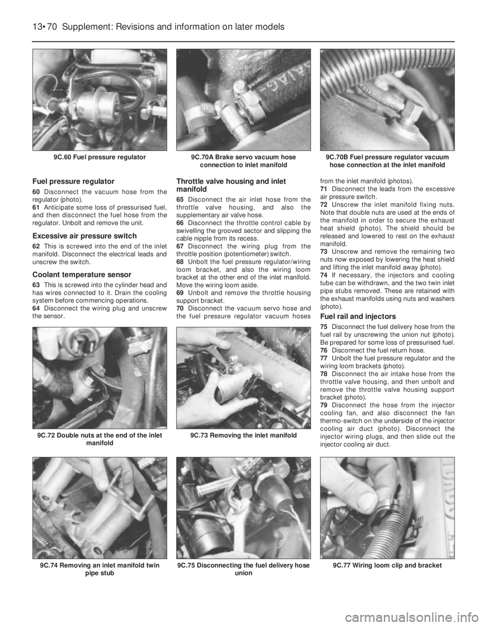
60Disconnect the vacuum hose from the
regulator (photo).
61Anticipate some loss of pressurised fuel,
and then disconnect the fuel hose from the
regulator. Unbolt and remove the unit.
Excessive air pressure switch
62This is screwed into the end of the inlet
manifold. Disconnect the electrical leads and
unscrew the switch.
Coolant temperature sensor
63This is screwed into the cylinder head and
has wires connected to it. Drain the cooling
system before commencing operations.
64Disconnect the wiring plug and unscrew
the sensor.
Throttle valve housing and inlet
manifold
65Disconnect the air inlet hose from the
throttle valve housing, and also the
supplementary air valve hose.
66Disconnect the throttle control cable by
swivelling the grooved sector and slipping the
cable nipple from its recess.
67Disconnect the wiring plug from the
throttle position (potentiometer) switch.
68Unbolt the fuel pressure regulator/wiring
loom bracket, and also the wiring loom
bracket at the other end of the inlet manifold.
Move the wiring loom aside.
69Unbolt and remove the throttle housing
support bracket.
70Disconnect the vacuum servo hose and
the fuel pressure regulator vacuum hosesfrom the inlet manifold (photos).
71Disconnect the leads from the excessive
air pressure switch.
72Unscrew the inlet manifold fixing nuts.
Note that double nuts are used at the ends of
the manifold in order to secure the exhaust
heat shield (photo). The shield should be
released and lowered to rest on the exhaust
manifold.
73Unscrew and remove the remaining two
nuts now exposed by lowering the heat shield
and lifting the inlet manifold away (photo).
74If necessary, the injectors and cooling
tube can be withdrawn, and the two twin inlet
pipe stubs removed. These are retained with
the exhaust manifolds using nuts and washers
(photo).
Fuel rail and injectors
75Disconnect the fuel delivery hose from the
fuel rail by unscrewing the union nut (photo).
Be prepared for some loss of pressurised fuel.
76Disconnect the fuel return hose.
77Unbolt the fuel pressure regulator and the
wiring loom brackets (photo).
78Disconnect the air intake hose from the
throttle valve housing, and then unbolt and
remove the throttle valve housing support
bracket (photo).
79Disconnect the hose from the injector
cooling fan, and also disconnect the fan
thermo-switch on the underside of the injector
cooling air duct (photo). Disconnect the
injector wiring plugs, and then slide out the
injector cooling air duct.
13•70 Supplement: Revisions and information on later models
9C.77 Wiring loom clip and bracket9C.75 Disconnecting the fuel delivery hose
union9C.74 Removing an inlet manifold twin
pipe stub
9C.73 Removing the inlet manifold9C.72 Double nuts at the end of the inlet
manifold
9C.70B Fuel pressure regulator vacuum
hose connection at the inlet manifold9C.70A Brake servo vacuum hose
connection to inlet manifold9C.60 Fuel pressure regulator