FORD B MAX 2012 1.G Owners Manual
Manufacturer: FORD, Model Year: 2012, Model line: B MAX, Model: FORD B MAX 2012 1.GPages: 256, PDF Size: 19.67 MB
Page 161 of 256
Downloaded from www.Manualslib.com manuals search engine USING WINTER TYRES
WARNING
When using winter tyres on yourvehicle, you must make sure that youfit the correct type of wheel nuts.
If winter tyres are used, make sure that thetyre pressures are correct. See TechnicalSpecifications (page 164).
USING SNOW CHAINS
WARNINGS
Do not exceed 30 mph (50 km/h).
Do not use snow chains on snow-freeroads.
Only fit snow chains to specifiedtyres. See TechnicalSpecifications (page 164).
If your vehicle has wheel trims,remove them before fitting snowchains.
Note:The anti-lock braking system willcontinue to operate normally.
Only use small link snow chains.
Only use snow chains on the front wheels.
Vehicles With Stability Control
When stability control is on, your vehiclemay exhibit some unusual drivingcharacteristics. To reduce this, switchtraction control off. See Using StabilityControl (page 103).
TYRE PRESSURE
MONITORING SYSTEM
WARNINGS
The system does not relieve you ofyour responsibility to regularly checkthe tyre pressures.
The system will only provide a lowtyre pressure warning. It will notinflate the tyres.
Do not drive on significantlyunder-inflated tyres. This may causethe tyres to overheat and fail.Under-inflation reduces fuel efficiency, tyretread life and may also affect your abilityto drive your vehicle safely.
Do not bend or damage the valveswhen you are inflating the tyres.
Have tyres installed by an authoriseddealer.
The deflation detection system will alertyou if there is a change of air pressure inany tyre. It does this by using the anti-lockbraking sensors to detect the rollingcircumference of the wheels. When thecircumference changes, this indicates lowtyre pressure. A warning message isdisplayed in the information display andthe message indicator will illuminate. SeeInformation Messages (page 62).
If a low pressure warning message isdisplayed in the information display, checkthe tyre pressures as soon as possible andinflate them to the recommendedpressure. See Technical Specifications(page 164).
If this happens frequently, have the causedetermined and rectified as soon aspossible.
159Wheels and Tyres
Page 162 of 256
Downloaded from www.Manualslib.com manuals search engine Apart from a too low tyre pressure or adamaged tyre, the following situations canaffect the rolling circumference:
•Vehicle load is uneven.
•When using a trailer or travelling up anddown an incline.
•Using snow chains.
•Driving on soft surfaces such as snowor mud.
Note:The system will still functioncorrectly, but there may be an increaseddetection time.
System Reset
Note:Do not reset the system when yourvehicle is moving.
Note:You should reset the systemfollowing any adjustment to the tyrepressures or any changing of tyres.
1.Switch the ignition on.
2.Using the information display control,navigate to Menu > Vehicle settings> Deflation detection.
3.Press and hold the OK button untilconfirmation appears.
CHANGING A ROAD WHEEL
Wheel Nuts
You can obtain a replacement lockingwheel nut key and replacement lockingwheel nuts from your dealer using thereference number certificate.
Vehicles With a Spare Wheel
If the spare wheel is exactly the same typeand size as the other fitted road wheels,you can replace the existing road wheelwith the spare wheel and continue to drivein the normal manner.
If the spare wheel is different to the otherroad wheels, it will carry a yellow label withthe appropriate speed limit.
Refer to the following information beforechanging the road wheel.
WARNINGS
Drive the shortest possible distances.
Do not fit more than one spare wheelon your vehicle at any one time.
Do not carry out any tyre repairs ona spare wheel.
Do not drive through an automaticcar wash.
If you are unsure what type of sparewheel you have do not exceed 80km/h (50 mph).
Only fit snow chains to specifiedtyres. See TechnicalSpecifications (page 164).
The ground clearance of your vehiclemay be reduced. Take care whenparking next to a kerb.
Note:Your vehicle may exhibit someunusual driving characteristics.
Vehicle Jack
WARNINGS
The vehicle jack supplied with yourvehicle should only be used whenchanging a wheel in emergencysituations.
Before using the vehicle jack, checkthat it is not damaged or deformedand that the thread is lubricated andfree from foreign matter.
Never place anything between thejack and the ground, or the jack andyour vehicle.
160Wheels and Tyres
Page 163 of 256
Downloaded from www.Manualslib.com manuals search engine Note:Vehicles with a temporary mobilitykit do not have a vehicle jack or a wheelbrace.
It is recommended to use a workshop typehydraulic jack for changing betweensummer and winter tyres.
Note:Use a jack with a minimum liftingcapacity of 1.5 tonnes and a lifting plate witha minimum diametre of 3.1 inches (80millimetres).
Vehicles With a Spare Wheel
Your vehicle jack, wheel brace, screw-intowing eye and wheel trim remover arelocated in the spare wheel well.
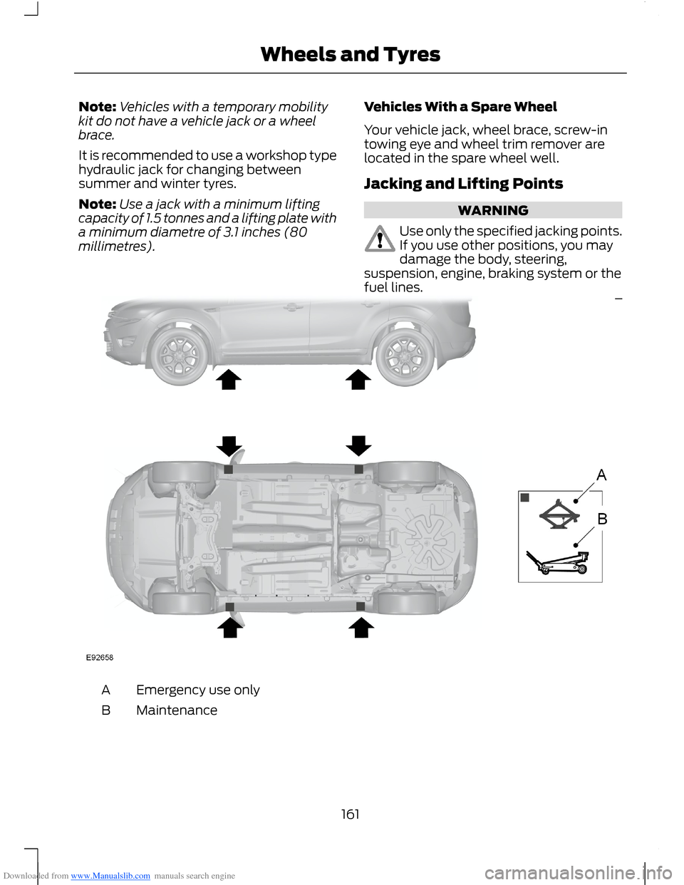
Jacking and Lifting Points
WARNING
Use only the specified jacking points.If you use other positions, you maydamage the body, steering,suspension, engine, braking system or thefuel lines.
Emergency use onlyA
MaintenanceB
161Wheels and Tyres
Page 164 of 256
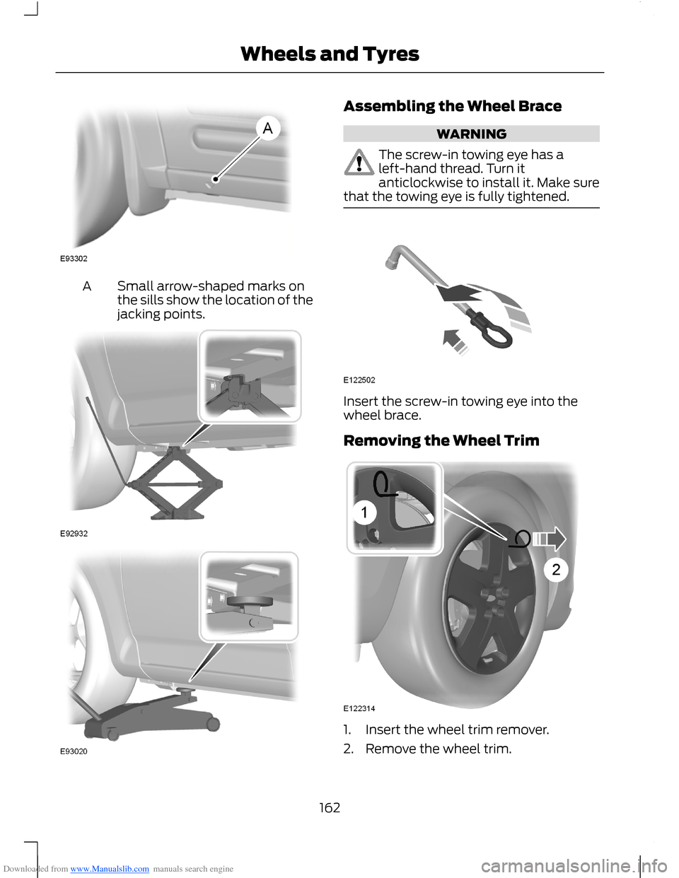
Downloaded from www.Manualslib.com manuals search engine Small arrow-shaped marks onthe sills show the location of thejacking points.
A
Assembling the Wheel Brace
WARNING
The screw-in towing eye has aleft-hand thread. Turn itanticlockwise to install it. Make surethat the towing eye is fully tightened.
Insert the screw-in towing eye into thewheel brace.
Removing the Wheel Trim
1.Insert the wheel trim remover.
2.Remove the wheel trim.
162Wheels and Tyres
Page 165 of 256
Downloaded from www.Manualslib.com manuals search engine Note:Make sure that you pull the wheeltrim remover at right angles to the trim.
Removing a Road Wheel
WARNINGS
Park your vehicle in such a positionthat neither the traffic nor you arehindered or endangered.
Set up a warning triangle.
Make sure that your vehicle is on firm,level ground with the wheels pointingstraight ahead.
Switch the ignition off and apply theparking brake.
If your vehicle has a manualtransmission, move the selector leverto first or reverse gear. If it has anautomatic transmission, move the selectorlever to position (P).
Have the passengers leave yourvehicle.
Secure the diagonally oppositewheel with an appropriate block orwheel chock.
Make sure that the arrows ondirectional tyres point in the directionof rotation when your vehicle ismoving forward. If you have to fit a sparewheel with the arrows pointing in theopposite direction, have the tyre refittedin the correct direction by an authoriseddealer.
Do not work underneath your vehiclewhen it is supported only by a jack.
Make sure that the jack is vertical tothe jacking point and the base is flaton the ground.
Note:Do not lay alloy wheels face downon the ground, this will damage the paint.
Note:The spare wheel is located under thefloor cover in the luggage compartment.
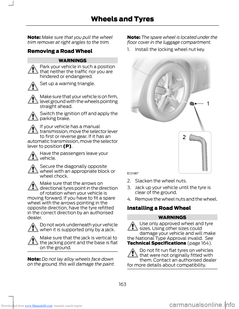
1.Install the locking wheel nut key.
2.Slacken the wheel nuts.
3.Jack up your vehicle until the tyre isclear of the ground.
4.Remove the wheel nuts and the wheel.
Installing a Road Wheel
WARNINGS
Use only approved wheel and tyresizes. Using other sizes coulddamage your vehicle and will makethe National Type Approval invalid. SeeTechnical Specifications (page 164).
Do not fit run flat tyres on vehiclesthat were not originally fitted withthem. Contact an authorised dealerfor more details about compatibility.
163Wheels and Tyres
Page 166 of 256
Downloaded from www.Manualslib.com manuals search engine WARNING
Do not install alloy wheels usingwheel nuts designed for use withsteel wheels.
Note:The wheel nuts of alloy wheels andspoked steel wheels can also be used forthe steel spare wheel for a short time(maximum two weeks).
Note:Make sure the wheel and hub contactsurfaces are free from foreign matter.
Note:Make sure that the cones on thewheel nuts are against the wheel.
1.Install the wheel.
2.Install the wheel nuts finger tight.
3.Install the locking wheel nut key.
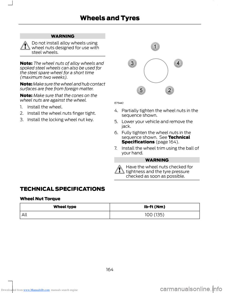
4.Partially tighten the wheel nuts in thesequence shown.
5.Lower your vehicle and remove thejack.
6.Fully tighten the wheel nuts in thesequence shown. See TechnicalSpecifications (page 164).
7.Install the wheel trim using the ball ofyour hand.
WARNING
Have the wheel nuts checked fortightness and the tyre pressurechecked as soon as possible.
TECHNICAL SPECIFICATIONS
Wheel Nut Torque
Ib-ft (Nm)Wheel type
100 (135)All
164Wheels and Tyres
Page 167 of 256
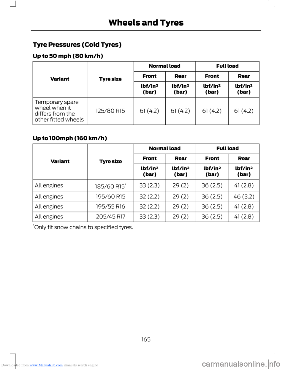
Downloaded from www.Manualslib.com manuals search engine Tyre Pressures (Cold Tyres)
Up to 50 mph (80 km/h)
Full loadNormal load
Tyre sizeVariantRearFrontRearFront
lbf/in²(bar)lbf/in²(bar)lbf/in²(bar)lbf/in²(bar)
61 (4.2)61 (4.2)61 (4.2)61 (4.2)125/80 R15
Temporary sparewheel when itdiffers from theother fitted wheels
Up to 100mph (160 km/h)
Full loadNormal load
Tyre sizeVariantRearFrontRearFront
lbf/in²(bar)lbf/in²(bar)lbf/in²(bar)lbf/in²(bar)
41 (2.8)36 (2.5)29 (2)33 (2.3)185/60 R15*All engines
46 (3.2)36 (2.5)29 (2)32 (2.2)195/60 R15All engines
41 (2.8)36 (2.5)29 (2)32 (2.2)195/55 R16All engines
41 (2.8)36 (2.5)29 (2)33 (2.3)205/45 R17All engines
*Only fit snow chains to specified tyres.
165Wheels and Tyres
Page 168 of 256
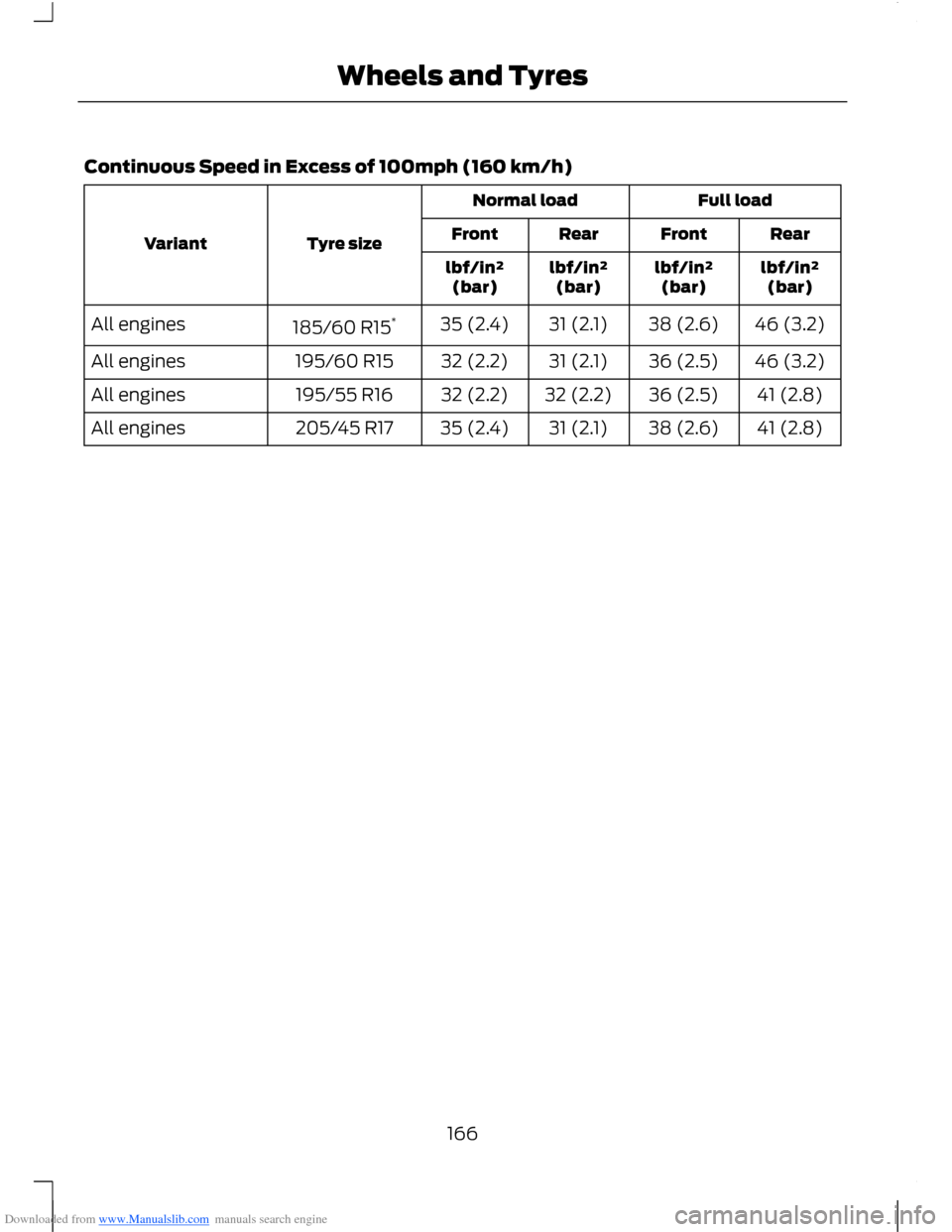
Downloaded from www.Manualslib.com manuals search engine Continuous Speed in Excess of 100mph (160 km/h)
Full loadNormal load
Tyre sizeVariantRearFrontRearFront
lbf/in²(bar)lbf/in²(bar)lbf/in²(bar)lbf/in²(bar)
46 (3.2)38 (2.6)31 (2.1)35 (2.4)185/60 R15*All engines
46 (3.2)36 (2.5)31 (2.1)32 (2.2)195/60 R15All engines
41 (2.8)36 (2.5)32 (2.2)32 (2.2)195/55 R16All engines
41 (2.8)38 (2.6)31 (2.1)35 (2.4)205/45 R17All engines
166Wheels and Tyres
Page 169 of 256
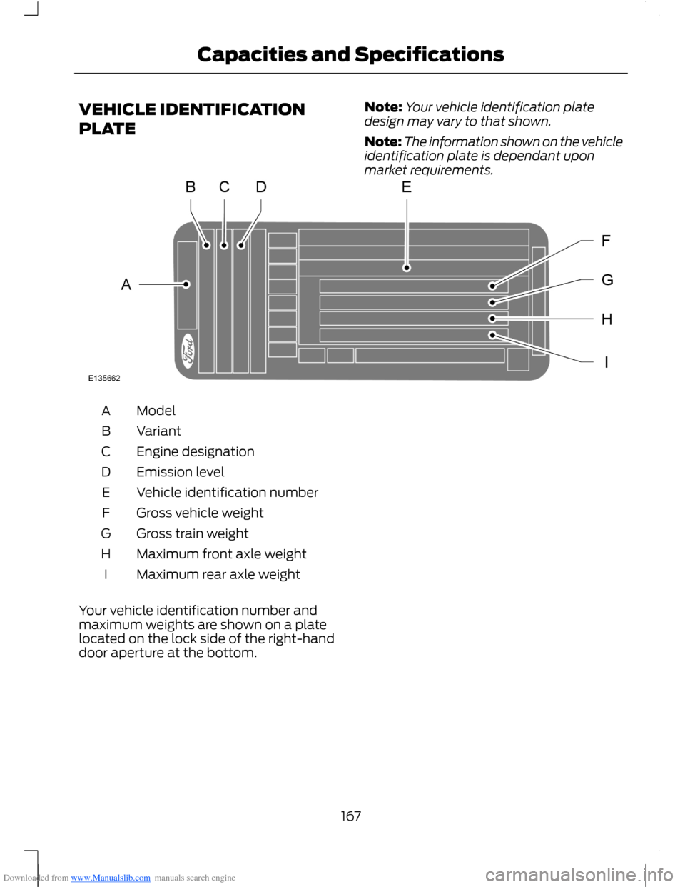
Downloaded from www.Manualslib.com manuals search engine VEHICLE IDENTIFICATION
PLATE
Note:Your vehicle identification platedesign may vary to that shown.
Note:The information shown on the vehicleidentification plate is dependant uponmarket requirements.
ModelA
VariantB
Engine designationC
Emission levelD
Vehicle identification numberE
Gross vehicle weightF
Gross train weightG
Maximum front axle weightH
Maximum rear axle weightI
Your vehicle identification number andmaximum weights are shown on a platelocated on the lock side of the right-handdoor aperture at the bottom.
167Capacities and Specifications
Page 170 of 256
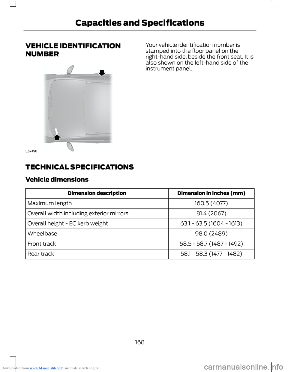
Downloaded from www.Manualslib.com manuals search engine VEHICLE IDENTIFICATION
NUMBER
Your vehicle identification number isstamped into the floor panel on theright-hand side, beside the front seat. It isalso shown on the left-hand side of theinstrument panel.
TECHNICAL SPECIFICATIONS
Vehicle dimensions
Dimension in inches (mm)Dimension description
160.5 (4077)Maximum length
81.4 (2067)Overall width including exterior mirrors
63.1 - 63.5 (1604 - 1613)Overall height - EC kerb weight
98.0 (2489)Wheelbase
58.5 - 58.7 (1487 - 1492)Front track
58.1 - 58.3 (1477 - 1482)Rear track
168Capacities and Specifications