fuse FORD BRONCO 2023 User Guide
[x] Cancel search | Manufacturer: FORD, Model Year: 2023, Model line: BRONCO, Model: FORD BRONCO 2023Pages: 642, PDF Size: 14.71 MB
Page 350 of 642
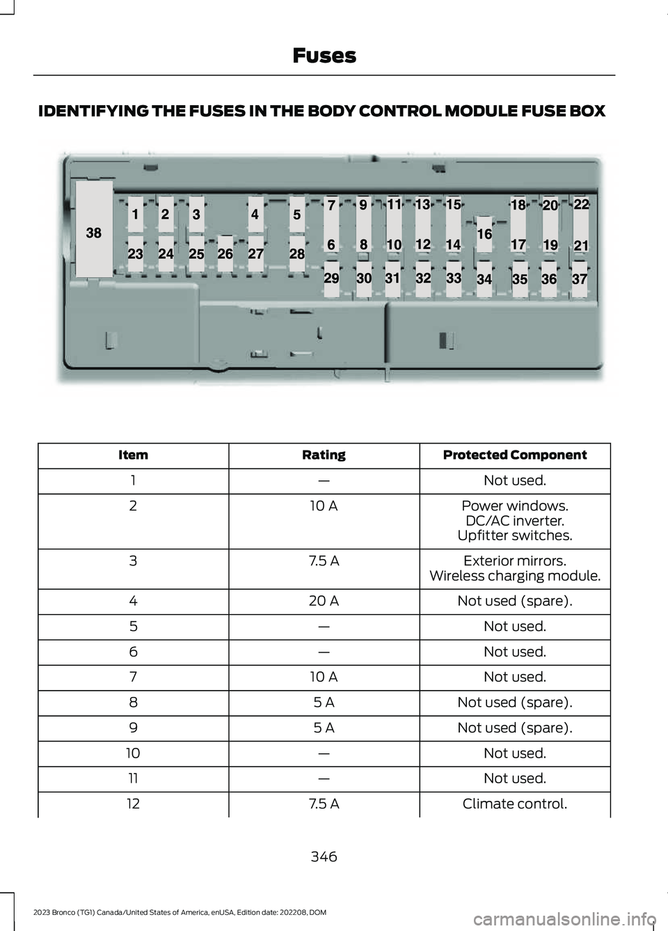
IDENTIFYING THE FUSES IN THE BODY CONTROL MODULE FUSE BOX
Protected ComponentRatingItem
Not used.—1
Power windows.10 A2DC/AC inverter.Upfitter switches.
Exterior mirrors.7.5 A3Wireless charging module.
Not used (spare).20 A4
Not used.—5
Not used.—6
Not used.10 A7
Not used (spare).5 A8
Not used (spare).5 A9
Not used.—10
Not used.—11
Climate control.7.5 A12
346
2023 Bronco (TG1) Canada/United States of America, enUSA, Edition date: 202208, DOMFusesE145984
Page 351 of 642
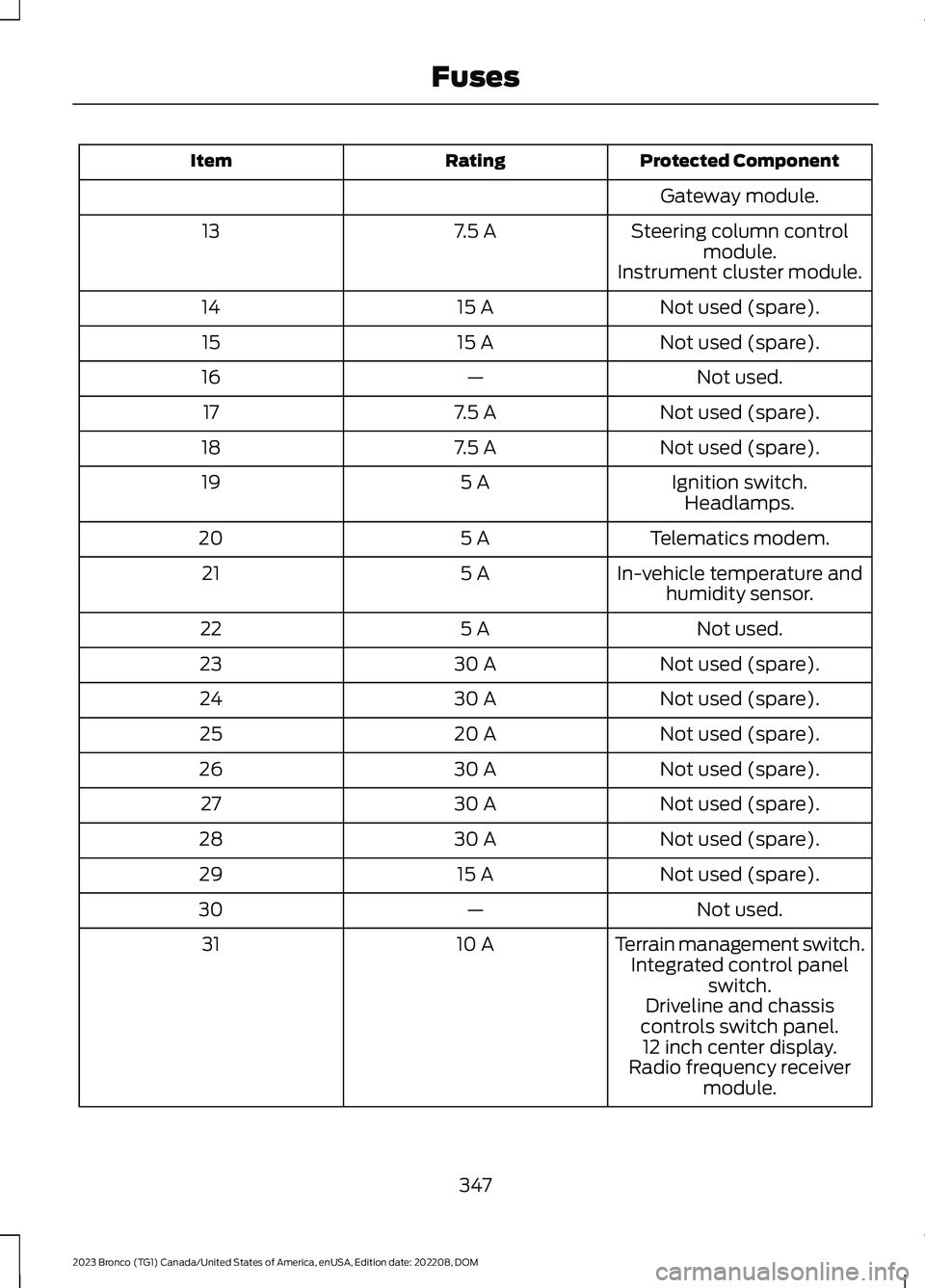
Protected ComponentRatingItem
Gateway module.
Steering column controlmodule.7.5 A13
Instrument cluster module.
Not used (spare).15 A14
Not used (spare).15 A15
Not used.—16
Not used (spare).7.5 A17
Not used (spare).7.5 A18
Ignition switch.5 A19Headlamps.
Telematics modem.5 A20
In-vehicle temperature andhumidity sensor.5 A21
Not used.5 A22
Not used (spare).30 A23
Not used (spare).30 A24
Not used (spare).20 A25
Not used (spare).30 A26
Not used (spare).30 A27
Not used (spare).30 A28
Not used (spare).15 A29
Not used.—30
Terrain management switch.10 A31Integrated control panelswitch.Driveline and chassiscontrols switch panel.12 inch center display.Radio frequency receivermodule.
347
2023 Bronco (TG1) Canada/United States of America, enUSA, Edition date: 202208, DOMFuses
Page 352 of 642
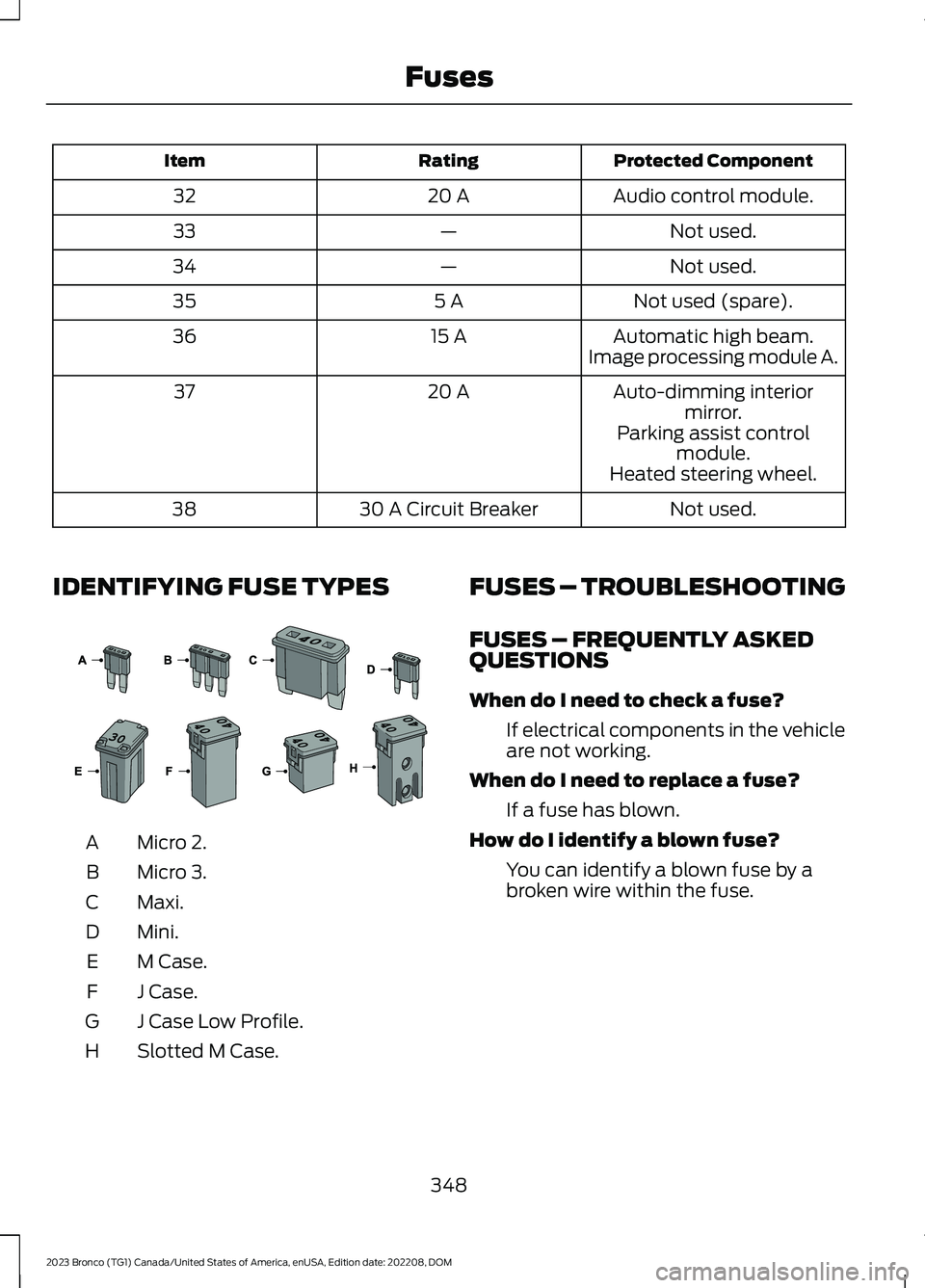
Protected ComponentRatingItem
Audio control module.20 A32
Not used.—33
Not used.—34
Not used (spare).5 A35
Automatic high beam.15 A36Image processing module A.
Auto-dimming interiormirror.20 A37
Parking assist controlmodule.Heated steering wheel.
Not used.30 A Circuit Breaker38
IDENTIFYING FUSE TYPES
Micro 2.A
Micro 3.B
Maxi.C
Mini.D
M Case.E
J Case.F
J Case Low Profile.G
Slotted M Case.H
FUSES – TROUBLESHOOTING
FUSES – FREQUENTLY ASKEDQUESTIONS
When do I need to check a fuse?
If electrical components in the vehicleare not working.
When do I need to replace a fuse?
If a fuse has blown.
How do I identify a blown fuse?
You can identify a blown fuse by abroken wire within the fuse.
348
2023 Bronco (TG1) Canada/United States of America, enUSA, Edition date: 202208, DOMFuses E267379
Page 356 of 642
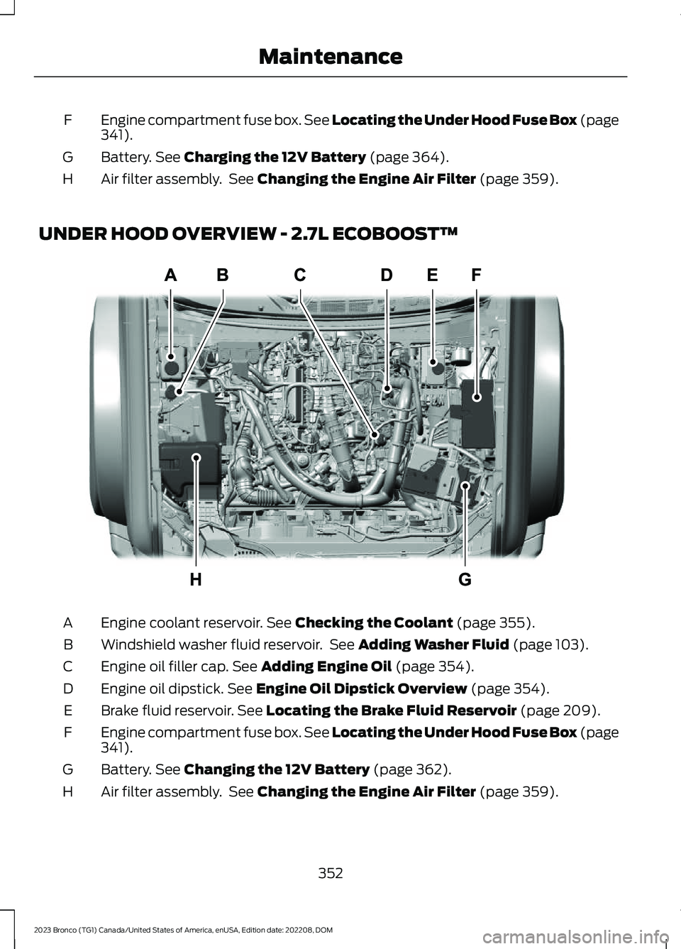
Engine compartment fuse box. See Locating the Under Hood Fuse Box (page341).F
Battery. See Charging the 12V Battery (page 364).G
Air filter assembly. See Changing the Engine Air Filter (page 359).H
UNDER HOOD OVERVIEW - 2.7L ECOBOOST™
Engine coolant reservoir. See Checking the Coolant (page 355).A
Windshield washer fluid reservoir. See Adding Washer Fluid (page 103).B
Engine oil filler cap. See Adding Engine Oil (page 354).C
Engine oil dipstick. See Engine Oil Dipstick Overview (page 354).D
Brake fluid reservoir. See Locating the Brake Fluid Reservoir (page 209).E
Engine compartment fuse box. See Locating the Under Hood Fuse Box (page341).F
Battery. See Changing the 12V Battery (page 362).G
Air filter assembly. See Changing the Engine Air Filter (page 359).H
352
2023 Bronco (TG1) Canada/United States of America, enUSA, Edition date: 202208, DOMMaintenanceE339862
Page 357 of 642
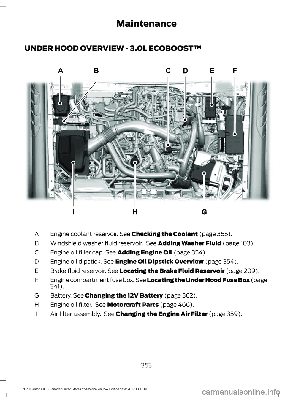
UNDER HOOD OVERVIEW - 3.0L ECOBOOST™
Engine coolant reservoir. See Checking the Coolant (page 355).A
Windshield washer fluid reservoir. See Adding Washer Fluid (page 103).B
Engine oil filler cap. See Adding Engine Oil (page 354).C
Engine oil dipstick. See Engine Oil Dipstick Overview (page 354).D
Brake fluid reservoir. See Locating the Brake Fluid Reservoir (page 209).E
Engine compartment fuse box. See Locating the Under Hood Fuse Box (page341).F
Battery. See Changing the 12V Battery (page 362).G
Engine oil filter. See Motorcraft Parts (page 466).H
Air filter assembly. See Changing the Engine Air Filter (page 359).I
353
2023 Bronco (TG1) Canada/United States of America, enUSA, Edition date: 202208, DOMMaintenanceE360711
Page 361 of 642
Water alone, without engine coolant, cancause engine damage from corrosion,overheating or freezing.
Do not use the following as a coolantsubstitute, as they can cause enginedamage from overheating or freezing:
•Alcohol.
•Methanol.
•Brine.
•Any coolant mixed with alcohol ormethanol antifreeze.
Do not add extra inhibitors or additives tothe coolant. These can be harmful andcompromise the corrosion protection ofthe coolant.
Severe Climates
If you drive in extremely cold climates, youmay need to increase the coolantconcentration above 50%.
Note:A coolant concentration of 60%provides improved freeze point protection.Coolant concentrations above 60%decrease the overheat protectioncharacteristics of the coolant and couldcause engine damage.
If you drive in extremely hot climates, youmay need to decrease the coolantconcentration to 40%.
Note:A coolant concentration of 40%provides improved overheat protection.Coolant concentrations below 40%decrease the overheat and corrosionprotection characteristics of the coolant andcould cause engine damage.
Coolant Change
WARNING: Do not dispose ofcoolant in the household refuse or thepublic sewage system. Use an authorizedwaste disposal facility.
Change the coolant at specific mileageintervals. Refer to the scheduledmaintenance information. See NormalScheduled Maintenance (page 531).
Note:Dispose of used coolant in theappropriate manner.
Follow your community's regulations andstandards for recycling and disposing ofautomotive fluids.
Fail-Safe Cooling
Fail-safe cooling allows you to temporarilydrive your vehicle before any incrementalcomponent damage occurs. The fail-safedistance depends on ambienttemperature, vehicle load and terrain.
How Fail-Safe Cooling Works
WARNING: If you continue to driveyour vehicle when the engine isoverheating, the engine could stopwithout warning. Failure to follow thisinstruction could result in the loss ofcontrol of your vehicle.
If the engine begins to overheat,the coolant temperature gaugemoves toward the red zone:
A warning lamp illuminates anda message may appear in theinformation display.
If the engine reaches a presetover-temperature condition, the engineautomatically switches to alternatingcylinder operation. Each disabled cylinderacts as an air pump and cools the engine.
When this occurs, your vehicle stilloperates, however:
•Engine power is limited.
•The air conditioning system turns off.
357
2023 Bronco (TG1) Canada/United States of America, enUSA, Edition date: 202208, DOMMaintenanceE103308 E67028
Page 408 of 642
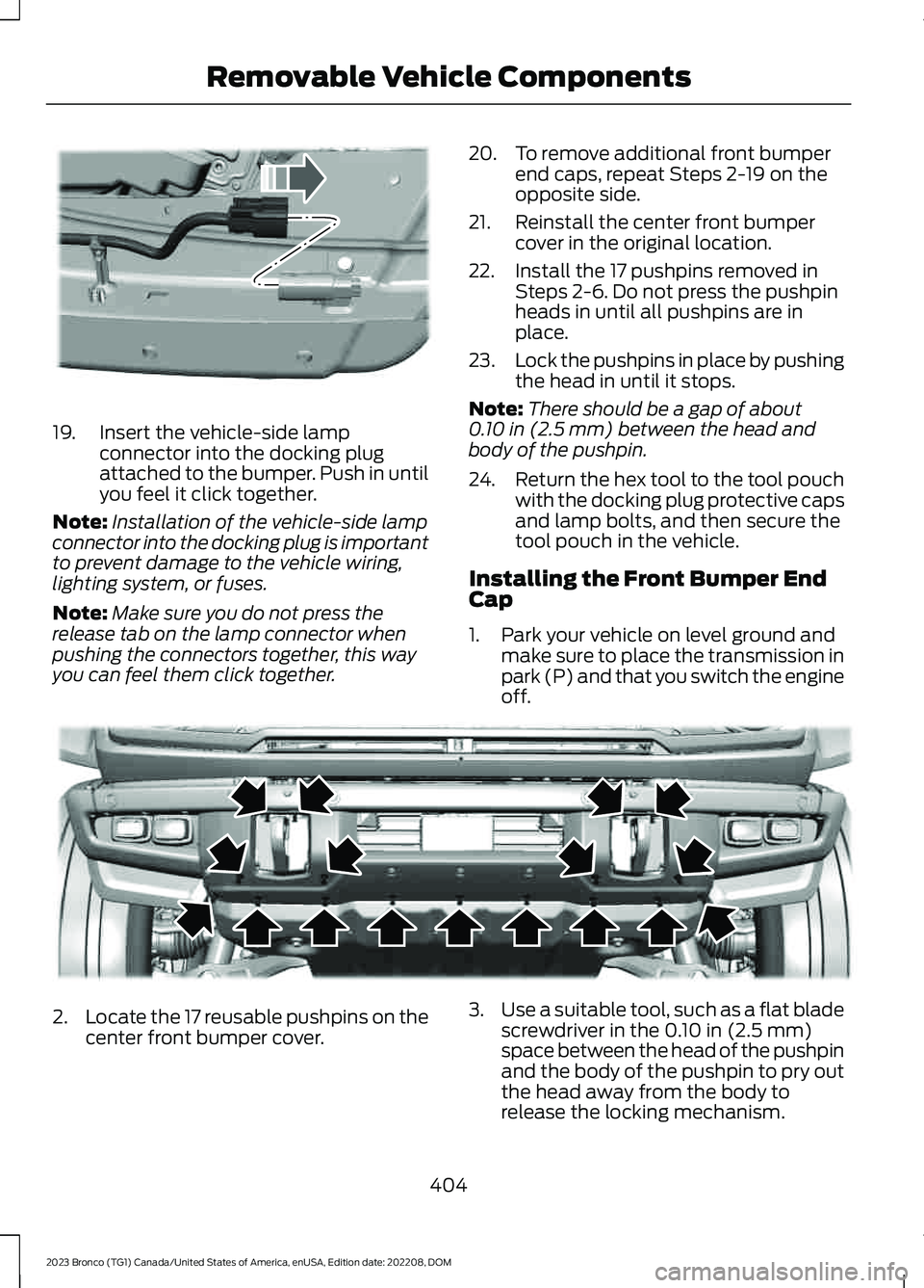
19.Insert the vehicle-side lampconnector into the docking plugattached to the bumper. Push in untilyou feel it click together.
Note:Installation of the vehicle-side lampconnector into the docking plug is importantto prevent damage to the vehicle wiring,lighting system, or fuses.
Note:Make sure you do not press therelease tab on the lamp connector whenpushing the connectors together, this wayyou can feel them click together.
20.To remove additional front bumperend caps, repeat Steps 2-19 on theopposite side.
21.Reinstall the center front bumpercover in the original location.
22.Install the 17 pushpins removed inSteps 2-6. Do not press the pushpinheads in until all pushpins are inplace.
23.Lock the pushpins in place by pushingthe head in until it stops.
Note:There should be a gap of about0.10 in (2.5 mm) between the head andbody of the pushpin.
24.Return the hex tool to the tool pouchwith the docking plug protective capsand lamp bolts, and then secure thetool pouch in the vehicle.
Installing the Front Bumper EndCap
1.Park your vehicle on level ground andmake sure to place the transmission inpark (P) and that you switch the engineoff.
2.Locate the 17 reusable pushpins on thecenter front bumper cover.
3.Use a suitable tool, such as a flat bladescrewdriver in the 0.10 in (2.5 mm)space between the head of the pushpinand the body of the pushpin to pry outthe head away from the body torelease the locking mechanism.
404
2023 Bronco (TG1) Canada/United States of America, enUSA, Edition date: 202208, DOMRemovable Vehicle ComponentsE366953 E366945
Page 526 of 642
WHAT ARE THE AUXILIARY
SWITCHES
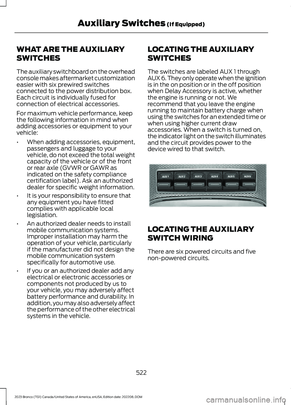
The auxiliary switchboard on the overheadconsole makes aftermarket customizationeasier with six prewired switchesconnected to the power distribution box.Each circuit is individually fused forconnection of electrical accessories.
For maximum vehicle performance, keepthe following information in mind whenadding accessories or equipment to yourvehicle:
•When adding accessories, equipment,passengers and luggage to yourvehicle, do not exceed the total weightcapacity of the vehicle or of the frontor rear axle (GVWR or GAWR asindicated on the safety compliancecertification label). Ask an authorizeddealer for specific weight information.
•It is your responsibility to ensure thatany equipment you have fittedcomplies with applicable locallegislation.
•An authorized dealer needs to installmobile communication systems.Improper installation may harm theoperation of your vehicle, particularlyif the manufacturer did not design themobile communication systemspecifically for automotive use.
•If you or an authorized dealer add anyelectrical or electronic accessories orcomponents not produced by us toyour vehicle, you may adversely affectbattery performance and durability. Inaddition, you may also adversely affectthe performance of the other electricalsystems in the vehicle.
LOCATING THE AUXILIARY
SWITCHES
The switches are labeled AUX 1 throughAUX 6. They only operate when the ignitionis in the on position or in the off positionwhen Delay Accessory is active, whetherthe engine is running or not. Werecommend that you leave the enginerunning to maintain battery charge whenusing the switches for an extended time orwhen using higher current drawaccessories. When a switch is turned on,the indicator light on the switch illuminatesand the circuit provides power to thedevice wired to that switch.
LOCATING THE AUXILIARY
SWITCH WIRING
There are six powered circuits and fivenon-powered circuits.
522
2023 Bronco (TG1) Canada/United States of America, enUSA, Edition date: 202208, DOMAuxiliary Switches (If Equipped)E220728
Page 527 of 642
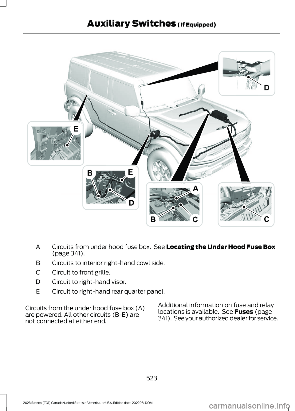
Circuits from under hood fuse box. See Locating the Under Hood Fuse Box(page 341).A
Circuits to interior right-hand cowl side.B
Circuit to front grille.C
Circuit to right-hand visor.D
Circuit to right-hand rear quarter panel.E
Circuits from the under hood fuse box (A)are powered. All other circuits (B-E) arenot connected at either end.
Additional information on fuse and relaylocations is available. See Fuses (page341). See your authorized dealer for service.
523
2023 Bronco (TG1) Canada/United States of America, enUSA, Edition date: 202208, DOMAuxiliary Switches (If Equipped)E343821
Page 528 of 642
IDENTIFYING THE AUXILIARY SWITCH WIRING - EXCLUDING:
RAPTOR
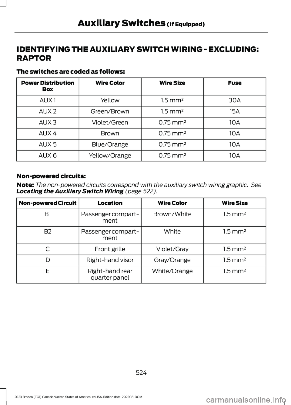
The switches are coded as follows:
FuseWire SizeWire ColorPower DistributionBox
30A1.5 mm²YellowAUX 1
15A1.5 mm²Green/BrownAUX 2
10A0.75 mm²Violet/GreenAUX 3
10A0.75 mm²BrownAUX 4
10A0.75 mm²Blue/OrangeAUX 5
10A0.75 mm²Yellow/OrangeAUX 6
Non-powered circuits:
Note:The non-powered circuits correspond with the auxiliary switch wiring graphic. SeeLocating the Auxiliary Switch Wiring (page 522).
Wire SizeWire ColorLocationNon-powered Circuit
1.5 mm²Brown/WhitePassenger compart-mentB1
1.5 mm²WhitePassenger compart-mentB2
1.5 mm²Violet/GrayFront grilleC
1.5 mm²Gray/OrangeRight-hand visorD
1.5 mm²White/OrangeRight-hand rearquarter panelE
524
2023 Bronco (TG1) Canada/United States of America, enUSA, Edition date: 202208, DOMAuxiliary Switches (If Equipped)