check engine FORD CAPRI 1974 Owner's Manual
[x] Cancel search | Manufacturer: FORD, Model Year: 1974, Model line: CAPRI, Model: FORD CAPRI 1974Pages: 205, PDF Size: 43.75 MB
Page 68 of 205
)
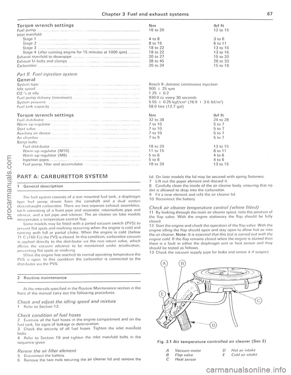
Chapter 3 Fuel and exhaust systems 67
Torque wrenc h setting s Fuel P\JlllP Inlet n'
G ene ra l SyS1c'" Iype Idl e sp ce d CO "o,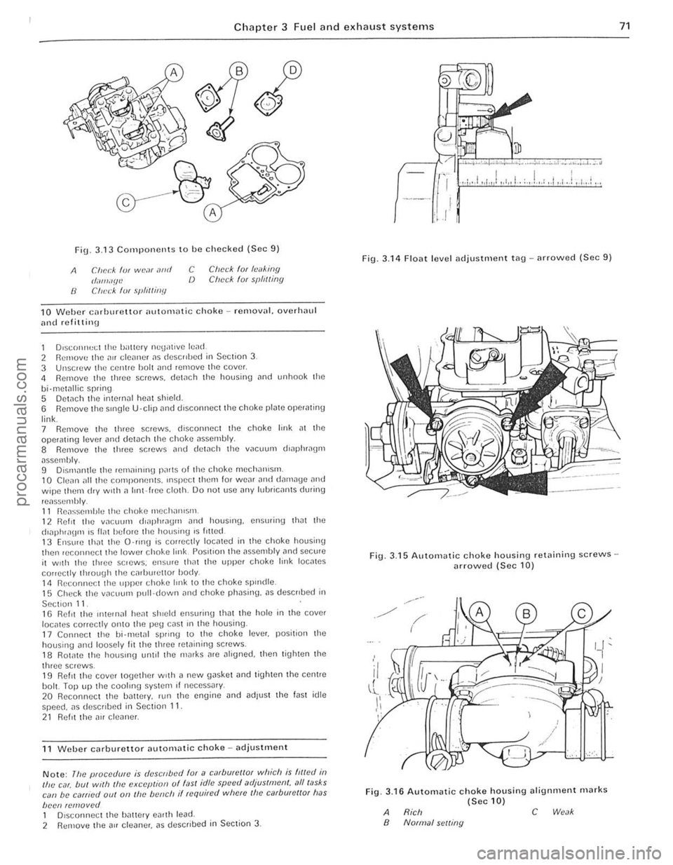
) Chapter 3 Fuel and exhaust systems
FiU _ 3.13 Components to he checked (Sec 9)
A
8
C/u':(:A fur wP.olf alJd (/illlli'f/I.l Clwck '(If .~/I"lIitJfJ
C CI)(xk for hd,ill{J {) Check (Of spfrlling
10 Weller cnrhurettor ""tom,lIie choke - rcmov,]L overhaul
and refitlinu
1 DlsconlH!~1 Ihe i)illicry nC\j
le"sselllhly. 11 Ik"ssemhle the choke meCh'1I11SI11. 12 Relit ll1e v"CUUIll til"phl1'lI)lIl alld hOUSII1,). enslllinu th"t lhe (hilphl,l()fIl IS lIolt before lile housing IS fllted. 13 Ensure thm the O-IIllg is correctly locmed in the choke housinU then reCOllnect the lower choke I",k Position the assembly and secure il WIth the thr ee sClews . ensure thnt the upper choke link loc"tes
cOlrectly tluouUh the c"rlJlJretlOf body 111 RecOllllec t the upper choke Imk to the choke Sp"l(tie. 15 Check the V"CUUIll pull· down
Note: lile pfOccc/
.l.I. .... , •• ,. ••. • .. .• . ,,~ ......... , •• , •• .;..,.: .•• ' •.•••• 1 . ;."
.,.', .,1,,/. 1,,' .. 1 . .. . , 1.,.: .. 1,.1.1,.1 .•. : ...
J
Fig. 3.1 4 F loat level adjustment t
.------
./ /' (
Fig.
/
3 .16 Automatic c hoke h ousing alignment (Sec 10)
A Rich c B Normal scl/lllg
marks
71
procarmanuals.com
Page 76 of 205
![FORD CAPRI 1974 Owners Manual )
Chapter 3 Fuel and exhaust systems 75
;\1.325 Prisillll oul tho re l<lin in\] clip (A) when removing IIIH acceluralOr callie (n) (Sec 1 7 )
~ fl""",V<: Ilw au eli!.",u. ;IS d .. ,~r."'J( FORD CAPRI 1974 Owners Manual )
Chapter 3 Fuel and exhaust systems 75
;\1.325 Prisillll oul tho re l<lin in\] clip (A) when removing IIIH acceluralOr callie (n) (Sec 1 7 )
~ fl""",V<: Ilw au eli!.",u. ;IS d .. ,~r."'J(](/img/11/56932/w960_56932-75.png)
)
Chapter 3 Fuel and exhaust systems 75
;\1.325 Prisillll oul tho re l
cOlll,,,1 IIIIK"!I" G I'll'." Ih" ",,,,,,1 '''','UHrI!l <:lIp hom the IlIi,,;k"l 7 U~"'!I a ~,:",wd"v"r. d"I"CSS tile pl
'o le: If /I" ., IU:(/"I ",!ly ,.~ to "(~ /f.'/!/oVI:1I /("1,:, (0 1""""1';'1"" 12 [)I~.,:,,,,,,,'cl (h" 1",lle,y lea(ls ? r",," liNd" t lw C,II lemove Ihe 1;)(;';1 It""", 1';,,,,,1 II I, '''WII\l:d hy ,,<'I(:W~ (IlHO) OIII""e S{;WWS (LHD) "IIIII!I Ihe ''',II "dUI! ami C;1Il tJ" IUH:lopp"d l,ulll lhe hont l~d\)c 3 n"lllove th" ,u;cole'''lot cilhlc hom Ihe p"dal sha h olS ((e~""h"d III
Secll"" 113
RI-IO variilnls 4 DI~(u"ncct Ihe IHake ope',IiIl1\J IOd ill Ihe b'ake ped;rl. thcn 'enluve tio" I"aslcr cylinder ,lilt! sc,vo lllHI nell" to Ch,lpl!!' 9 101 lUll lol'l
'nl')lll1alI1111
5 WO,kllll) I I"OIl\)h (he ,e,l' bulkhead III the C "IJ"'C vo"'p,"t""!1I1. pull Ollt lire sh;rft "nd S"CUI1I1() chp () Rotate Ihe I1\)ht·h,,,,d Shil l I IIIO'"ltlll\) bush Ih,ou\)h 45' ,n e'lhe' d1lCC1l011 ;)nd pull II Out 7 DetaCh Ihe
AI/models 11 Oetach II", 'em;lIl\ll\Y bush ;rm] clIp hOIll lire shalt. ) To re11l0V" the pedill, pl1se the f!;ln\Je ilway Irom the SPIYO( on lire snail. lhell ,emove the p"dal and sp"ng 13 WI,en ,eflll"'!! tire pedal. locilte the sp''''U on Ihe SPIUOI shall, lilr,, clop th" 11""\)"$ 01110 Ihe SP'\JOIS ilnt! check lhilt Ihe pcd;)1 I"vots
cO"lIetl),
Fig. 3.26 Accele ra to r cable rc moval 1001 (Sec 1 7 )
A _ 250",,,,(10,,,)
() ~ Cell(fe IlUlidl /11 /J!Uv;d" ',1,SL'd -'''ullld ... ,
14 ncllll"'() the pud.ll shilft ,s Ihe ,eve,su 01 Ihc lelllov,,1 IHocerhllC, lolinwlllU whIch It w ,lI he 'H!CUssa,y to ;ullllS I It,,) cailic. "5 d"scllt)IJ d 11 Si,(.t'OIl 16 OIL Rill) v;",allts. dlcck lh;ot the I)(:d;oll"'$ 6 tn 14 ",m (02" 1{) 0 55 'Il) I,ft 110'" the nflu posit 'on If IIo,,"ss.u y ild)"st Ih!! pedal
Iofl up ~!Op !O ach'"ve I h,s
19 1"lc t Ill[l"il o ld -rClllov;l1 ilnd rcfitting
1 DIsconnect (he biltlc,y ne(),1Ilve IUild. 2 D'illli Ihe coolm\) syslem (Chapter 2). ,emovc Ihe d'StllIJU1{)I (Chapl", 4), and remove the C.llilll'et!O' (SectIon 8) ] DI~<:OIlI,,:ct til!! rl!m,IIIiUlI) hoses ;rlld Willi'\) <1 UllSV,P.W the 'nlet m;r,ulold holl~ p'ouress,vd), III II", ",v,,'~r: oldl)I 10 that lflvell II, 1"1) 327 5 LIft 11'1) II,let Ill;H"lold frum tlH! o:yhlHit;, hr:;lds ;",(1 II''''
\)IVCll '" the Spec,fr~.lt'ons 10 The '''lllillll'''\) proced",e IS" 'eve,s,,1 01 ,elHoval rlefrlllhc cool",'J s)'stem WIth Icfe'cnce 10 CI"lpte, 2
Fig. 3.27 Inlet III,mifold bolt tightening sequcnce fo r 3.0 litre engines (Sec 19)
procarmanuals.com
Page 80 of 205
)
Chapte r 3 Fu el an d exhau st systems 79
Ii
0) G
\E )
' .. ~ ee)
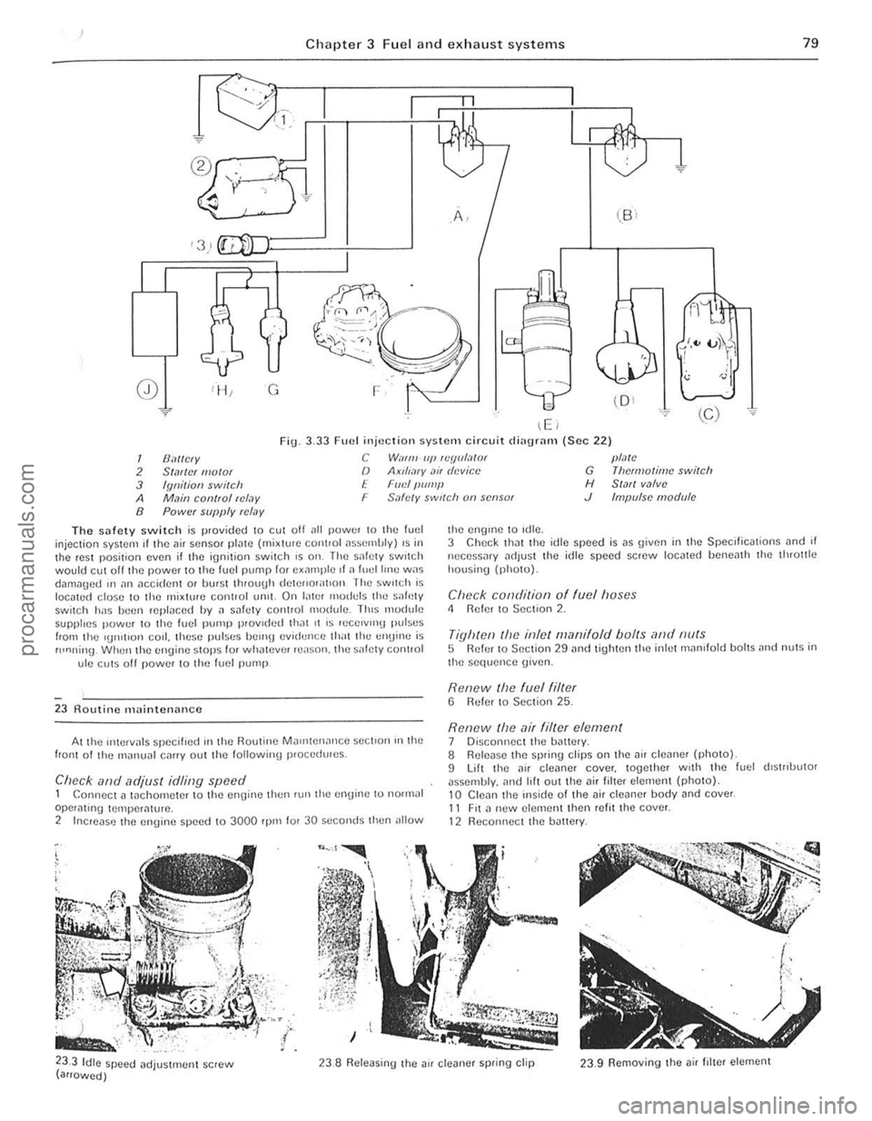
Fig. 3.33 Fuel injuctiOIl system circuit di
2 Sialicr I/Iolor /) Axll/,-"y ,1i, device G Theo1lO/lmc switch
3 fgnitioll switch E FIII;I/Iump H St,lfl valve
A M,lin con(Iol r(;/,)y F S
8 Power supply rcl.1Y
Tho safety switch is provided to cut olf illl power !O the fuel injection sySl(!m if the air sensor plJIC (mixt\HC COlllrol assemhly) IS il the rest position even if the ignition switch IS all. The s[lfcly switch would ell! off the power to the fuel pump for oillllpic ,I il fllOJllmu W
AI the IntelV
,. ,
< '(:,,~ , • . . ;::~t,·· . , ,
.' ) . ;~ ~~;:;: ~iJ" .. ,
n fr.X l
the engllle 10 'die.
3 Check Ihill I he idle speed is lIS given in the Specificmions ilnd il nccnssary "dlust the idle speed screw 10cllted heneillh Ihe Ihrottle housinv {photo).
Check conditiorl o f fuel hoses " Reier to SeClion 2.
Tighte/l the inlel manifold boilS and /luis 5 Refur 10 Section 29 and lighten the inlel rll
Renew the air filter element 7 Disconnect the h
-
I',
I t, ' .
;
!
" , ' .• I
! 1 I'
: 1'1 1 . ,
I
I '
I
procarmanuals.com
Page 83 of 205
,
~ Chilpter 3 Fuel and exhaust systems
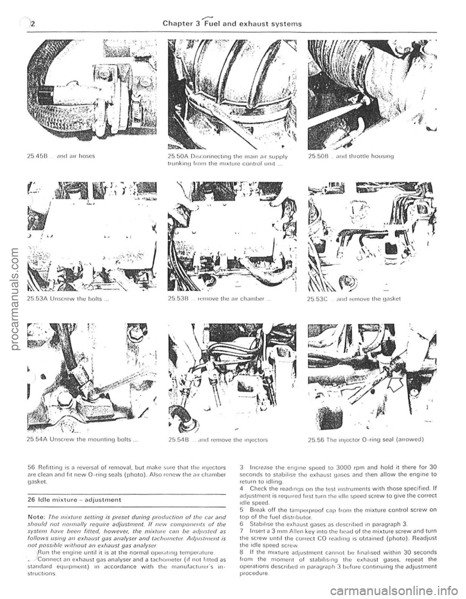
~5 4513 ,111<1 "'f hose s 2550A D",conneclinu the maUl "" supply t.unkul!! 1.011 the 1111~hue cont.ol 111111 25501l mid th'OI1I C houslIlU
"",'
25 53A UnsCII)w the holts. 255311 ,,,"U)IIC the ~'" chal11bcr ~5 53C ;11111 'cmoY(: the Haskct
,
25 5 4A UlIsc'ew the 11101l1lt;IIU bolts. 2554 U ,lIld remove the UIIL'CtOrs 2556 The "'Jecto, Q·rinU seal (a"owed)
56 Rcl,llll.g IS 11 reve rsal 01 rcmoval. hut mtlke SUiO Iha l til.., "l)OC Iors .IIC clea n and III new O'lIng seals (pholo). Also rencw the;IU chamber gtlskel.
26 I( H o mixture -adjustment
Noto: 11!e miJllllfe s"/liIl9 is preset during (!for/actiOIl of II", eM ,'nd shOll1ll 1101 "ofllwll~ require "djIISlment. If I!~'W r:QfIIl'O"Cllf.~ l)f 'he sys({)m ""VI! bccn flllCd. IlOwever. tile mix/IIII! (;,1/1 be mi,l/steil as lollows "Silly /II) cxlwlls/ y,l$
3 Incroase the enyulC speed 10 3000 'pm and hold it the,e 10' 30 seconds to Sl
5 Break oft the lalllpl:q)lOol cap 110111 the mj~ture conlrol screw on lap 01 Ihe fuel uistllbulOi. 6 S tabilise the cxhausl Ua ses as dcscllhc·d ,n paragraph 3. 7 In sert 11 3 r1\I AUcn key onto Ihe heau 01 the mixture SCfew and tum the SCfew urlld the COlfeCI CO re
procarmanuals.com
Page 89 of 205
Q
Chapte r 4 Ignition system
®
0 -
-@ @
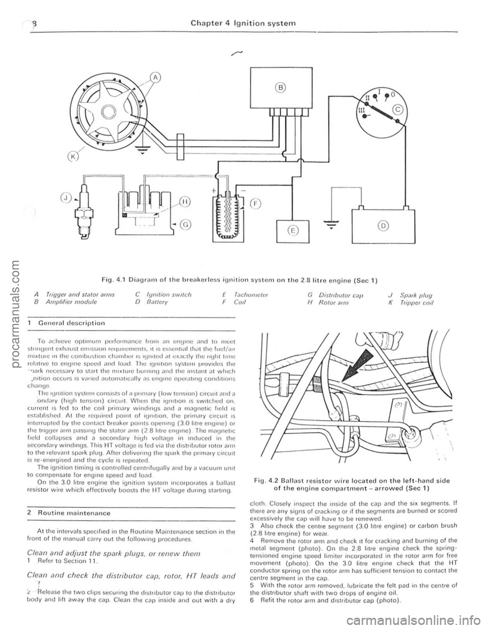
Fig. 4 .1 Diagwll1 of the hre(lkerlcs5 ignition syslem on the 2 .a litre engine (Sec 1 )
A higgcf ",,(I stiltor ,1(111$ 8 Am/Jlt/icf modufe C Iylll/ion SWJ/i:lr o BMI£'fY E 'm:lmJIIl"/l:f F COIl G D is/nUll/a , c.-,/! H Ho/or .11111 J 5p,1fK, IJ/ug K 'fi''l)CI co,1
Gcneral de:;criptio n
To ;l(; h.cvc OP\I"'U'" pCl lo.mancc hom an CIl(lUlC ;\Old In mCCI ~1""\JCUt e.h,1u~t C""5s"m r .. '
f 'eld collilpscs :Ind il 5tlCOndntV hi~h YOIIIl~~ In 'nduced i n the se~ond,1rv win(lin\!s. This HT volt:lUc IS te d via th e d'SH ,IJUtor rOIOI :Iun
1 0 the lelevllllt spnrk plu~. Alter dcllvenng the spar k the pmnnrv cirC Uli
I S re-energised lind the cvcle .s rep-Cillcd. The igni tion t iminu '5 Controlled centro lugllllV JnO UV II vacuum IHl II t o compensme lor englflC speed ,1no 10lld On Ihe 3.0 litre enginc the i~l1;lion s y Stelll II1corporales a b,1ita $1
resistor wire which effcctively UOOSIS th e HT volw~e durlllg SHul,ng.
2 Routine m aintenance
At Ihe in tervals speCIfied in tl w Rouline Ma;ntenance section in the fran I of the nl;Jnua l cJrrV out the foll owmg proc edures .
Clean and adjust Ihe spark plugs. or renew Ihem 1 Refer to Sec tion 11.
Clean ofld chec k fhe distribulor cop. rolor. NT leads illlr/
t. Re lease the twO chI'S securmg Ihe (h Slllbu101 cap 10 Ihe d'5111l1utor uodV and I, ft away t he ca l) . ereJn Ihl;l C:lP inside and oul wilh a dtv
---we F
Fig. 4 .2 (J"II(ls t resistor wire locilted on tho left·h'Hld side of the ongino compartment -urrowed (Sec 1)
clO lh . Closely inspec t the ",side of thc cap and the si. segments. It there are any siUns of Cr<1Ckulg 01 ,f the segmentS are bumcd o. scorl;ld e~cessivelv the Cal) will h ave to be renewed.
3 Also Check Ihe cenlrc segment (3.0 htr a en\]ine) or carbon brush (2.8 IIlre engine) f or wailr. 4 Remove the rOIOI arm i1nd check 1110 ' cra ck ing and burning of the melal scgmem (pholo). On the 2.8 h ire en gin e check tM Sp
d
procarmanuals.com
Page 90 of 205
) Chapter 4 Ignition system 89
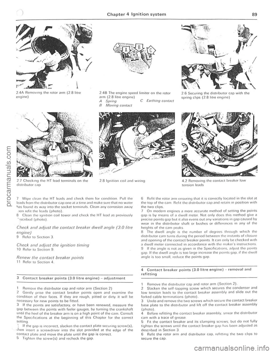
2,4A ncmovllI\J the ' 010' rum (28 hire enuino) 2413 The engine speed tllnnel 011 tho ,oto. :lIm (2_8 litre ename) 26 Secul;nn lhe dl surUlllor cap wilh Ihe sp.;ng clops (2.8 "lie engme) A Swing C fail/lillY COIlf.lCt n MQving CQII/act
27 ChcckUl!J Ihe HT tcad le.min;!ls on the (hSlllhutOf 1:.111 2 .8 11I"iliol1 COlt and WlIlIl!! 4 .2 Remov,ng I he COlllaCI h.eilke. low lenS 'OIl le,lds
7 W"H) o;iean the HT Itlad,; llm! check Ihc'" 10' (;onll'[IOI1 Pull the 1(';'Ids homlh!) dl~l"h"10f Cilll one;H
Check .1nd Mljus( (h£! cont<1c t brc<1ker dwell "flyle (3.0 fi/re
engillt!) !l Ruler to S
Reflew /lit.' conl,1CI breaker points 11 Reier to Secuon 4 .
3 CO I1\aet ureaker points (3.0 litr e er>gine) -adjustment
1 Remove thO dis touutor cap and ro tor afln (Sect ion 2) 2 Gentlv I)rrse Ihe contact ureaker points open and e~an\ine the conditIon of Iherr faces. II they are .ough. pined o. dlfty II WIll ue IlCCeSSi\'y 101 new paIn IS to be fined. 3 If Ihe pOInts ale sallSfaclory. Or have been ,enewed. measu.e the gap Uel ..... een the points with feele . gauges. by turning Ihe Clankshaft unlll I',e heel 01 Ihe ureake. arm is on a high poinl of Ihe C
5 Tlghlen Ihe sClew(s) and .echeck Ih e gap.
6 Rein the .010. ;"1IU1 ensurIng th,lt II IS cOflectly located In the sial at
I he lOp 01 the carn Relltlho d'SI"lJuIO' CilP and .elain III IIOS;llon wnh Ihe Iwo clIps . 7 On 1110de.n el1gll'os a mo.e ,1CCu'ale mel hod 01 seHIIlg Ihe I>o;nts Hal) .s by means o f a dwell me lel . NOI only docs 111110 l11elhod give a
IHL'Cisc 1)0 .. 115 gap I)UIII also evens oul ally v,llta llons 111 Un,) cnused by wear "' I he dlst"'lUtor sh ah 01 uushes 0' dlHCf()nce s HI any 01 the heIgh ts 01 Ihe Cil'" peilks 8 The dwell allU1c IS Ihe numt)C. 01 deglee s th, ounh winch Ihe
dIstributor cam lUI liS dUring the IlCrlod betweell Ihe ",S\ilIlIS 01 closu
4 Conlilct hre[l ke r points (J.O litre engine) -removal and refitting
Remove the d'SlflbutOi C"P and 'OlOr arm (Secl;on 2) . 2 Slacken th e self·tappiu\J sc.ew which secllres the condense. illld low lension lead s 10 the conl,lel ureake. ilssembly ilnd slide oul lhe fo.ked cable telfllll,al;OnS (phOIO). 3 Undo and .emovc Ihe Iwo screws whIch secu.e the contact b.eake' uase pll'Ie 10 thO d'SlflbulOr ilfld hit off the cUlltact b.eaker assembly
(phOIO) .
4 Befo.e IClilling the conlact b.eake. assemhly. smear Iho dlstrluu to . cam wllh a trace 01 g.ease 5 FIt I he conlaC I 1)I(,ake' and its cl,Jlnping sr.;.ew~. but do nOI fully I;ghten the sc.ews \lnlll Iho contilC I b.eake. !I,111 h;IS u een adlusled as descflbed In Sec tion 3
6 R ell l th e rotor "fin and d.stflhuw. cal ). ""'1I"'~1 tI,e IWO clops 10 secure lhe cap.
"
, ,
: I
procarmanuals.com
Page 91 of 205
90 ) Chapter 4 Ignition sys tem
' .
. ' =-,,":.
:f/~jI
iJ -~
, .. '
k~
~
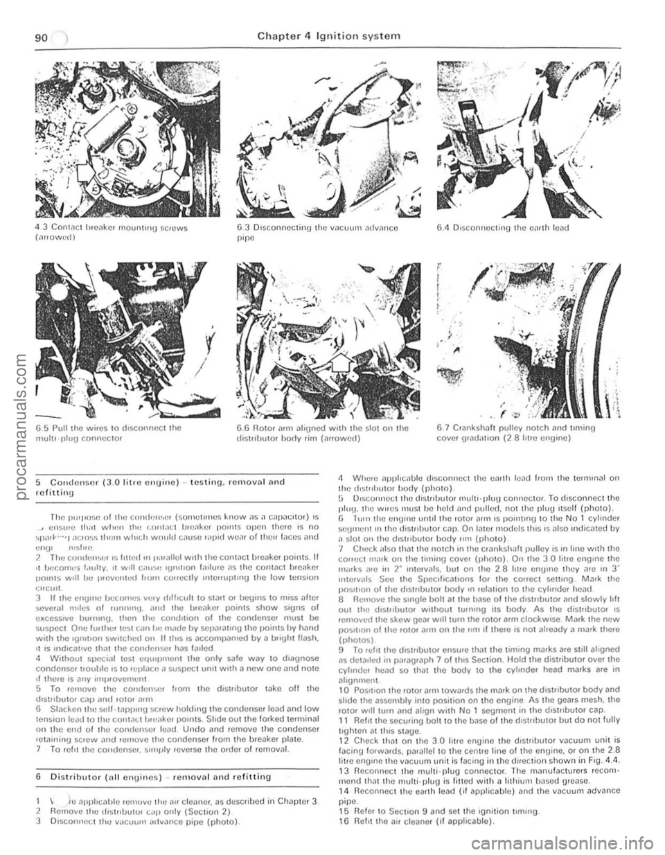
<1 3 Contact hlcnkc. mOUIlJrrlO ~CH)WS (,lrrowcd) 63 Dlsconncclinu the V
(
/
r
I
I
I
,
. '. f
'1,j , , , ,
65 Pull tile wires 10 rhSCOlll1CCl the mull"I)I.,\) COlll1eClor 6.6 flOIO. arm al;\jncd with the slOI on t he d,strlhutor hrnly rim (allowed) 6 .7 C'ilnkshall polley nOlch and Imling covel gr,1(lahOn (28 hIre cn!l'ne)
5 Condenser (3.0 l itrf~ rnllJillo) -testing. removal (lnd rcf ittinu
The PU'I'OSI) 01 tilt) ccmd"",.er (sorllclull(!S know .15 .1 capacItor) IS ensure lh.1I wli,m II", ',()IIi."; ( I!UJakcr POUllS open thew IS no ~po1'~""1 a~Hl"S ilWlll whIch would C,llIlie ,ap,d weill 011hcu r .. ees ilnd
'!I'Il' ",slue 2 The CUIHIUIlSt" .s hUed !II I>luallel wnh the conlJCI h,e;)kc. points. II '1 becomes r""lly, ,1 w,lI C;II,,'" 'IJ'''IIOI' fa,lure ,15 the conlilCl hreaker 1'011115 1'0',11 he pH)VI!fIl,:ti hom cOllcclly 1Il1elfurlcmu che low ccnsion qrCIIIL 3 II Ihe en!)'lIe becomes very dlHlcul1 co SWrl 01 begins to I11ISS afrer
severill null'S of I lInl1l11\l . and che I)lcilker poinls show signs 01 e l\ceSSlve blllllllll/. Chen chI) condlu o n of Ihe condenser muSI be suspecI One f".ther !C:.t can II" milde hy sepa,ahl1U che points by hilnd wilh the ,umtlon 5WIICtl(:(1 on IItl"5 IS ilCCOoul),,"Il1led by a mighl trash. II IS ,ndu;:allve Ih .... 1 the comlcuscr has I0111cd
6 D istributor (illi en\)ines) -rcmoval and relittin\)
1 k ,1pphcablo II.HlH>VU the 1111 ele,me" ilS descllbed in Chapler 3
2 Remove Ihl! dl ~l"bulo' C;Ij> only (SeClion 2) 3 D,sconlle\:t Ill.., V
1 1 Relit the securing bolt 10 the bnse of Iha dlSlrrbulor bUI do nOt fully Ilghlen ;IllhlS Slage. 12 Check 11I11t on Ihe 3.0 hlr a engme the dlstrlbulo, VJcuum unil is lilcing fo,wilrds. parilliellO the centrO line of Ihe el1\)ine. or on Ihe 2.8 lil,e engine Ihe VilCUIIIll unil is lacing in Ihe duection shown in F ig. 4 .4 . 13 Reconnect Ihe IllUlli·plu\) conneClor. The manlJf~Clurers recom· mend Illill Ihe Illulli·plu!) is 'illed wilh il lilhium hased grease. 14 fleconneCllllu earlh lead (it applicable) and t he vJCUUm advance pipe. 15 Reier 10 Section 9 and se l Ihe 'gnition IlmlllO. 16 Refll Ihe all cleane. (if applicable).
procarmanuals.com
Page 92 of 205
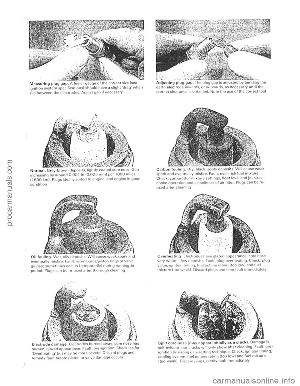
Monsurin g plug gnp . gaugo ;;:;;;-;;;"",,',,"," ignition sysICm spccilicalions) should have a sliUht 'drag' when slid between the olocuuch~s. Adjust {[liP if necessary
N orm al. r, dcpo~il~.liUlolly coaled corc nose. increasing by around 0.00 1 in (0.025 mm) pc, 1000 miles (1600 km). Plugs ideally suited to en\j ine. "nd engine in good
condition
Oil fouting. Wet. oily dr~pOl;its. cal,se eventually misfirc. Fllult : wmn bores/ilision 'ingSOf valve guidcs: sometimes OCC"'!! (temj.lO'Hrilyl d .. ring lunning-in
poriOd. Plug~ C()I1 IJ() H! u~ecl "ftc. thorouUh cleaning
-," ..
. \\'
in Electrode demoge. ;;;;,:;;;;;;;:;;;~;~;';::;;i ;;,,, ",,;; h;,
bumed, glazed appearance. Fa ult: pre')gnohon Check: as 101 'Overheating' bllt may be more sovero. Discard plugs ar1d rornedy fault belorc piston or v31vc d~",age occurs
.'
.. ", . ~,'''':c." ~~:~~~~~~::i, Adjusting plug gap. Tlu, plug gap is, 03rth electrode inwards, or oulwards, as I correct clearance is uillaim!d. NOlO II,,! use 01 tho COlfcct tool
spark ami I I' Chock: cMhulOllor , • sellings, 1I0al level ,lIld iot siles; c hoke (lJlOla lion .mel cltlanli n()ss 01 ai, fillel. Plugs can bo rcusod
vlJlue, iunitiun limill H. I"clu t;lillle I1Itillu (tOO lowl
i Split cor o noso (mny npllollI i 8 crBck). Damage is
sel f.evide nt, bUI cruc ks will only showalter cloaning. Faul t: preignition 01 wrOIl!) !)ap settin!) technique. Check : ignition liming,
cooling SYStCIl1. 1",,1 O C t;"" .. r alin!) (too low) and fuel mixlure lton woak) . Discilld "Iu!)s. ",Clllv laul t immediately
procarmanuals.com
Page 93 of 205
![FORD CAPRI 1974 Owners Manual Chapte r 4 Ig nitio n sys te m
6,SA Unsc rew the clamp bolt, 680 ... and remove the (tistJlbu to. 68C Rotor nnn alignmen t ;]lter re movnl Irorn engine
~ I
~.
F ig . 4.3 IU "i\iol1 timinu ma FORD CAPRI 1974 Owners Manual Chapte r 4 Ig nitio n sys te m
6,SA Unsc rew the clamp bolt, 680 ... and remove the (tistJlbu to. 68C Rotor nnn alignmen t ;]lter re movnl Irorn engine
~ I
~.
F ig . 4.3 IU "i\iol1 timinu ma](/img/11/56932/w960_56932-92.png)
Chapte r 4 Ig nitio n sys te m
6,SA Unsc rew the clamp bolt, 680 ... and remove the (tistJlbu to. 68C Rotor nnn alignmen t ;]lter re movnl Irorn engine
~ I
~.
F ig . 4.3 IU "i\iol1 timinu ma,ks o n the 3,0 lit.e e:1Uine (Sec 6)
Allow ;//(lic<1leS din'cliu" 0' !(JIM;oll
7 Distributor (3.0 litre engine) -overhaul
W,th the diMJlhuto. removed from the entl,ne. 'emove the rotor arm and the cont.1CI breaker assembly . 2 Prose Ihe small Clfclll} I'om the v"cuum u,,,t p,vo l IXJSt. 3 flemove th e two sc,ews wh,ch sucure the hfllaker pl,lI!! to Ihe d,slJlbu tor body and hit the ,}I'rte orl.
" Slacken Ihe self'lappmg SCfew which SC<:UlCS the condense, and low tenSion leads 10 Ihe contact l .. eaker a ssembly and shde OUI Ihe lo.ked ca ble terminations, 5 Undo imd remove Ihe condenser rCI.1,nlfl!.l screw and remove the condense •. 6 Remove the c" chp. lIiJt washer and wavy wash er from the pivot post. Se parat e the two plates by h,ingmu the holding down se,ew Ihrough Ihe keyhole sial in Ihe lowe. 1)late , Ta ke care not 10 lose the e.Jrt h spring on the prvo t flOst. 7 Remove the two se,ews seeu"n\) Ihe vilCuum un,t to the d IS t"lHIIO' hotly .Jntl remove the vacuum uni t. S To d,snl.JllIle Ihe vacuum unll, remove the plug I.om the end 01 the
unit (md withdraw the spring. vacuum stOp and shims 9 Oelo,e disll1<1ntling th e centJllugal .Jtlvance mech.Jnism. note thM th e tw O spri ngs arc d.lle.ent and ma,k them so th.Jtlh ey .Jre ref'tled in th ei r OJlgHlall}lilces . Remove the sp. ings. pJlse all the circ lil)S securong the cenlJlluga i weights. nl.J.k the weight s 10 'dent'fy their o"ginal positions and then remove them ,
1 0 M3
x - ------:::-.
z
y -
Fig . 4.4 Distrihutor lilting position on the 2.8litrc e ngine (Sec 6)
XX Re.1r "U;,.' of ellgmc yy V,1CI/(JIII flllil Mas Z = 0 '10 11/'
A Triggcr (lffll U Slillor l!fII!
whICh'S Ihen exposed Ilntl ,emove ,I L,lt all Ihe Ci"n and 1l(IV3ncc plJle ;Issemul y,
12 Do nOI .cmove t he d,stJluutor Sl)indle unless II 's necess.l'y to "1 a new ge.n. 0' S I)iJldle To remove Ihe uear . usc <1 IlUnch Ilnt! hJmmer t o dJlve outlhc lock P'" and Ihon pull tl)() !.Ic", frO'11 Ihe sprndle T"ke cn,e
1 0 rOIil'" ilny slums, 0' wllshe,s wh,ch fll.Jy be In led . W,t h the ueJ' lell'Ov\:(\. the sl)lIldle .Jsscmbly can be withd,awn hom the d ,s'Jlhu tor 13 Belore reassembhng. ca,elully clc.J1l the body 01 th e d,s lnbulOr and "II a s CO'llpo llent p"'ts. II th e sp,n(!ie has been .emoved. lulmenlC II w'lh e'lu",e oil h efor e ,ellssemhly. 14 Reassenlbly.s <1 SUa'ghtIOrw<1Jd ,eve'SilI 01 d,sman tling bUI t he,e Inc several pointS which shoold be noted.
15 Lut)JJc;]te th e ce Jltlil ugnl weights and otho. p3rtS ol the cenlrifugal
advnnce mechanism. the diSlrrbutor shah a nd Ihe pa'l 01 the spindle wh,eh c.l"'es Ihe cam assembly. using engine all. Do not orl excess,vely. 16 " Ih e dr'veshnlt hilS heen .emoved. firSt re fi t th e thru st wash ers below tho action plnte. bolore "'se,ting the S h .l h into thc disl. ih llto,
hody . FII the w3vy washer .Jnd IhrUSI washcr to the lowe! end 01 the shah and then relilthe ge.Jr. secuJlnU it with a new spring p in. II a now gear. or a ne w u"ves hnfL h,15 been fllt ed . a n\lW hole should be d"lIed .1t 90' 1 0 Ihe e~is'U1g hole 17 Alte • .Jssemhhng the centJll ug.J 1 weIgh ts .Jnd sprrngs. check that Ihl!Y movo hccly. w,thout I)inding, 18 8clOle assemblmg Ihe breaker pla tcs . make sure thill the three nylon bearing slUds a.e located "1 tht) h oles ,n the uPllC' uearinU plale and Ih3tthe e.Jrth,ng sprrng ,s foiled to the p,vOt post 19 On complet'on of assemlJly. adlust the conlnCl b'eake , gilp to the spc cified selling
procarmanuals.com