check engine FORD CAPRI 1974 Owner's Guide
[x] Cancel search | Manufacturer: FORD, Model Year: 1974, Model line: CAPRI, Model: FORD CAPRI 1974Pages: 205, PDF Size: 43.75 MB
Page 95 of 205
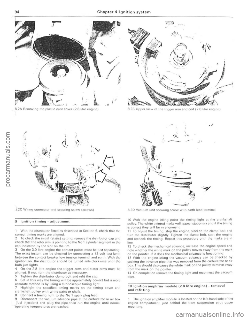
94 Chapter 4 Ignition system
i ' .
. --8 2A Removill{J the IllnSlre dust COve, (28 hl'c Cllume)
./ :,
, , ,
(\. I ,
" 'v
J 2C W'''I1!j connector i'Uld seCUJlIlg screw (lHOwS)
9 Ignitio n timing -adjustment
Wnh the (.lIs\"OuIO' III!Cd ilS dcscllbed OIl SectIon 6, check Ihilt 1Ill! COHCCt llllllng m;l!ks "'0 ;1119110d. 2 To check the ;1111,,11 (5 t;1I,e) setting, .emovc the (I'51"lIu I0' c;lll [11l\( check IhJllhc rOl0' ;lIm IS PO"1I1119 to the No 1 cylmdc. scgmon!.n the Cill) rndlcmed by the sial on the 11m. 3 On the 3.0 lUre engIne the cont,le l poullS ll\u~1 he ,ust SCI)ilril\U'!J Tho e~ilCt Instant C,1" he checked by connect"'u il 12 vol1 lest lamp between the contilC, brcilke r low tenSIon Iemur),,1 iUl(t O,"lh, W,th the iUnilion Oil, tho d is trlbuto. ShOllld be turn ed nrl\,·clockwisc unlol lho bulb luSlligh(s. " On (he 28 li(re enuule the ("gger arms and stator ;HIllS must bc aligned It not. (um I he (hst"bulOr as necessary . !:i Tighten the (hSI"buto. clamp boll and .ehl the cap 6 Set In thIS way the lUlling WIll be alll)'Olmalely co
8 2B UtJlle. vIew 01 the l.imJer Mrn .lrld Call (28 lIt Ie enU"Wj
.1
,I,
.. .."
8 20 Vacuum un.1 sC(:u"ng screw WIth e')Hh lead termmal
10 W,lh Ihe enij1l1e I(lIrng pornt thc \fmlng hgh( at the cr",lksholl1 pulley The wh,le 1),1mte
12 To check the mechanrcat adv.1nce. Increase the engIne speed and note whelher the wh,te malk on the pulley moves away Irom the mark on th e pOInter . 11 It docs the mechanical advance is lunctioning 13 W,th the enOlile Idlmu the vnCU\ Jm advance can be checked by suc kIng the oldv~ncu pIpe that W.1S removed from the carburellOI o r air box ThIS should also c.Juse the while rnark on the pulley to move away horn the mar k on the pointer 14 On completIon remove Ihe timlllU hght and rC(:onnec lthe v.1CUUIll pIpe
10 Ignition illlllllifier module (2.8 l i tre enuine) -removal and rClittinu
Thc Iunitlon illl\J}l lflcr module is locmed on Ihe left· hand SIde of the engIne COnlpar tment. tUSI behind Ihe hOnt suspenSIon strut upper mounting.
procarmanuals.com
Page 97 of 205
,6 Chapter 4 Ignition system
9 The spark plug gaf} is 01 conside rable impor1~e. as. if it is too lilrge or too small. the size of the spark ilnd its efficiency will be seriously impilired. The spilrk plug should be set to the ligure given in thl} Specifications ill the beginning of this Chapter; IOTa sel it, measure the gilp with a/cere, gauge. and then bend open. or close. the outer plug electrode untillhe correct gap is achieved. The centre electrode should never be benl as this may crack the insulation ilnd cause plug fAilure if nothing worse. 11 Relit the plugs, and re/ilthe leads from the distr ibu tor in the correct I"ing order. which is given in the Specifications. Screw the plugs in by hilnd initiilily then tighten them to the specified torque using the plug spilnnel.
12 Fault diagnosis -ignition system
By lar (he nlo1jori (y 01 brCJkdown and running troubles ilre caused by InUits In the igrlOlron system er(her in (he low (enSlon or high tens ion circuns There
Engine fails 10 staft 1 If the engine falls to StM( and t he cal was IIJnning norll1t1l1y when.t wns IJst used, first check ther e is fuel in the petrol wnk. If (he engille tums ovel normally on (he starter 1I10tor and the bilHery is evidently well chmged. then the lault mny be in either the high or low tension circuits. Firs( check Ihe HT circuit. Note: If lire hal/cry is known 10 hI! {(Illy ch,}lged, Ihe ignilion liglll cOllies on, ,1I)d Ihe s/arler 1II010r {,lils /() tum IIIe ongine check the tightness o f the le'lds on the biltlely terillinilis ,1I)d <1Iso (lte seCUIIHWSS oflhe e,l,th leold (0 irs cOllllec/ion 10 tire body It is qui(e common for tlie le,1(ls /0 Ii,}ve wOlked loose. l.'vc'1I If Ihey look ,1n(/ lecl seclI,e. /I one 01 the boll/my ((:{minM {Josts [11.'1.1' vC'IV liot wi".." (Iyiny (0 wOlk Ihe s/mler 1II0tOl (his is ;/ sUie IIId'C,7/IUI/ 0/ ;/ I;wlty COllllel;('On 1(1 1h.11Ie"lIillal. 2 One of tile commonest rOilsons lor bad stmtln!J IS wet or d;UllP sp,uk plug lead~ and dlstribu(or. Hemove (he distllblltor cap. H "JOdenSil(Ion is v iSIble IIlte!llillly dry the CJp With il rag and also wIpe ;lCf the leads nelu the cap_ 3 If (he enUiue sull fmls 1 0 St.l.t. check that cunent IS reachlllg (he JUS, by dlscounectln!1 ench plug le,l<1 in turn ilt the sp1Hk plllU end, .. ,ld holdlllg Ihe end olthe callie about 5 mm (0.2 Ill) aWilY from the cylillder block. Spin the enu'ne all the sta rter motor. 1 Spa,klllg between the end of the cable ilnd Ihe block should he fa"ly strong With J strong leuulm blue spark_ (Hold (he lead WI(h wbber to ilvold elec(IIc shocks) If Clluelll is reilching (he plugs. then rel110Ve them and clean and reg,lp them. Tho engine should now SWrt 5 If there is no spilrk ilt the plug leilds. wke of! the HT lead from the cenlre of the d'sltibutor C
Engine misfires 10 If the enOlnr. mlsfues re!Julariy. run It ilt a f~st irllrng speed. Pull off eilch 01 the plu(! C,lpS III hUll nnd hsten t o (he note 01 the engrne. Hold the phl(J cnp In il dry cloth or with a rubber g love
(,J) The cOllm.lV be {,lufly giving ,111 iniNmil/elll mislile (b) Thele limy he ,1 (/iJmiJged wile or loose cOrlflee/ioll in till! low (eflsion circuil (c) The condensel /II,lY I;e shOll circuiling (i{ filled) (d) There nwy be a meehanic,lllolUI! IiI Ihe dis/flbll/or (bfOken dliving spindle or eOlllac/bleaker spring. if filled)
17 If the ignition (iming is too far reto1lded, it should be noted thallhe engine will tend to overheat. and there will he a quite no(iceable drop in powel. If the engine is overheating and Ihe power is down, and Ihe ,oni(ion tim in!) is correct. then Ihe carburenor or fuel injection should be checked, i1S ,I is likely that this is where the Iilult lies.
procarmanuals.com
Page 107 of 205
·06 Chapter 6 Manual gearbox and automatic transmiss io n
disengilge the gearbox inpu t Shill! hom ,ho clutch p,Iot bearing ,111(1 clu tc h friction disc. I, is imporlanllhal,hc engine and transmi ssion <'lre kept in lino while this is being done. 14 When the gearbox shaft is cleDr of the clutch, remove th e
tran smissio n assembly from bCn(!illh the car.
15 When refiuing, ensure 1il1 the clut ch pilot h earing in the end althe tfilnksha h is ill plilce Jncl is scrviceDble. Tic the clutch lever 10 the clutch housing, 1 0 pr(!venllhe release le.rertrolll slipping out while the ,Wnsmission assembly is being lined. 16 Smear some molybdenum-based grease OntO the end and splines 0' the gearbox input s!mh lind refit the gearbox by reversing the fcmovili p.ocedure. 17 II is impO.IMll when offering up the {jOMOO)(. th,lt il is e~
slightly until the splines enter Do not iluempltO lo.ce the tfilllsmisslOn
ontO thO enlJlnO ThiS Illay (i
'8 Ahe •• el,uinn has been completed. chuck the 011 level Ifl t he .r
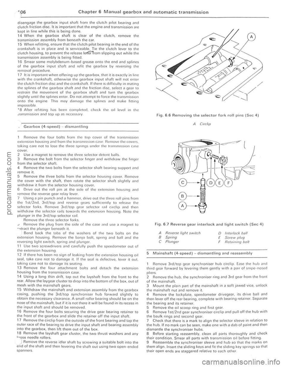
Romoye the lou. bolts hom the 1011 cove. 01 the t.ansm.sslon c~t()"sion housin!J ilnd f.om the lri"'snHs~ir)Ol eo'S<' Ilcmovflthc \:oye. s.
t.1king c
R emoYo the .eyerse idle , shah by sc.ewing a suitable bolt into Ihe end of Iho shah and then leye.ing the Sh;'lit Out uSing Iw o open ·ended spanne.s. Fi\)
.
6.6 Removing the seleclor 10lk rolillins (Sec 4)
A CIfC/'11
Fin. 6 .7 Revorso gear interlock nnd light swil c h (Sec 11)
A Ravelse liyh, switch 8 Swing C Plf/ngcr
o h!/ellocl< ball E Sc,ew IJlug
Rct.1ininy bolt F
5 M
thud gear lotwald lly lel/erinu the,n gently wrth a p
their condition. Smear all Pi/ItS wilh tr3nsmission 011 befo.e fitting .
9 Reassemble the synchroniser sleeve and hub so that the nlafks on thorn align . Inse.t the sliding keys and 1IIIhe shdrn\) key sp"ngs so Ihat Ihei. open ends afe stagge.ed re lat ive 10 each other
procarmanuals.com
Page 124 of 205
Chapter 6 Manual gearbox and automatic transmission 123
When towing a vehic le wIth automl11ic uansmission it is impoltllllt to observe the precautIons gIven til ,he 'Jading and Towing' se<:,ion at the Iront 01 the manual. Due to the complexity of the au'oma',c tran smission unit. If performance IS not up 10 s tandard, or overhaul is necessary, it IS impera tive that this be left to the locallllain agents who will have the special equipment for fault diagnosis and rectiflcallon. The content of the following sections is thereforc confined to supplying gener", Informl11ion 1'Ind any service information and ins t.uc tion tha i cnn be used by the owner.
19 Routine Illilinte,wno
At the i!lle.vnls SI)CClfiecllll Iho ROllllne Milintennnce seCIlOll in the I.onl 01 th e Illanllal cnllY Oul Ihe follOWIng p'ocp.dwe
Luuricow selector link'1[}() , Applv the h;rrldh.,lke th(:n J,lck \lp the front of Ihc Cill ,'lid Support
,n nxle Slnnds
2 Orlthe Irnkn!JCs at cndl end 01 Ihe genrsh ,h rml on the Icfl·hnnd "le 01 Ihe Iransnll~s,on lowel the cnr \0 Iho wound,
Check /mn.Wllissioll fluid level 4 Elrlll!! the engIne and trnnsnllSSlon to nOllllal ope.IlIUl!IIp.llIperillllfe
and I)alk tho vehlchl on le vel grOllnd 5 Wi,h Ihe engIne idllll(l. move tht: 1.,lnsnllSj"on St:leclt>r lev!]r through ill! pOSlllons 1!lIee lImes. Ihen onuaue '1" ,11111 wall for ;rt lea~t one minute. 6 With ,he engine 51111 idling, wllhd.ilW Ihe lr.1nSnllSSIOll d,psllck.
Wipe it dean, reinsert II, wilhd •• 1W 11 for Ihe second !line nnd read off the levol. 7 Two tv pes 01 automatic transnllssion fluid a.e nvarlilblc (sec SpccifiCiltions 10' tv,>c numbe.s) .1nd It is ImpO,I,ln , Ihilt IheV 'lIe nOI mixed. The colour 01 the dipstick. 10' flUId level checklllg denotes which fluid tvpe to use , 8 If a tlr1nsnllssion requlII"U 1,1ter tvpe fluid IS I'lled 10 " to'
adjus'or screw n lew h,fIlS . 13 Tlghlolllhe adJuslo, sOcw to 14 Nm (10 Ihl II) IISIilU a SUItable lo,que wrcnch From Ih,s poSlllon slaCken the adJusle r screw bv exact Iv I'll \Urns (pre·1983 models) or 2 Iwns ( 1983 and late,
model), Ihen tighten Ihe locknut Wllhoul diSlUrblllg Ihe pOsition of Ihe adjuster sc,ow .
14 R econnec t the downshift cable and lowe' Ihe car 10 Ihe ground.
20 Automalic transmission -removal (HId refining
If l)Osslble, ,aise the car on a hOlsl o. place it over an inspectIon pit. Alternatively, it WIll ho necessary 10 Jack up Ihe car to obtain the Illaximum possible amount of wOlking room undernealh. 2 Place a large d.ain pan benealh the transmiss.on sump (011 pan)
Ihen. working horll the ,car, loosen the a!laching boilS and allow ,he lIuld to drain. nemove all thO bohs excep t tho two I.onl ones to draIn as mIlch fluid as pOSSIble, th on temporarilV .efit Iwo bolls at th e re,1I 10 hold it in place . 3 Remove tho Slilrte. moto. as desc.ibed in Chapter 12 . • jWhero apphcable, rernove the access cover Dnd ad3pto, plale bolts,
Ie the engine untrl the to.qu e converter drain plug is visible, then
unsc.ew Iho plug and d.ain Iho Ihud Into a suit3ble con winer. Refl! and l'Uh ten Iho plug.
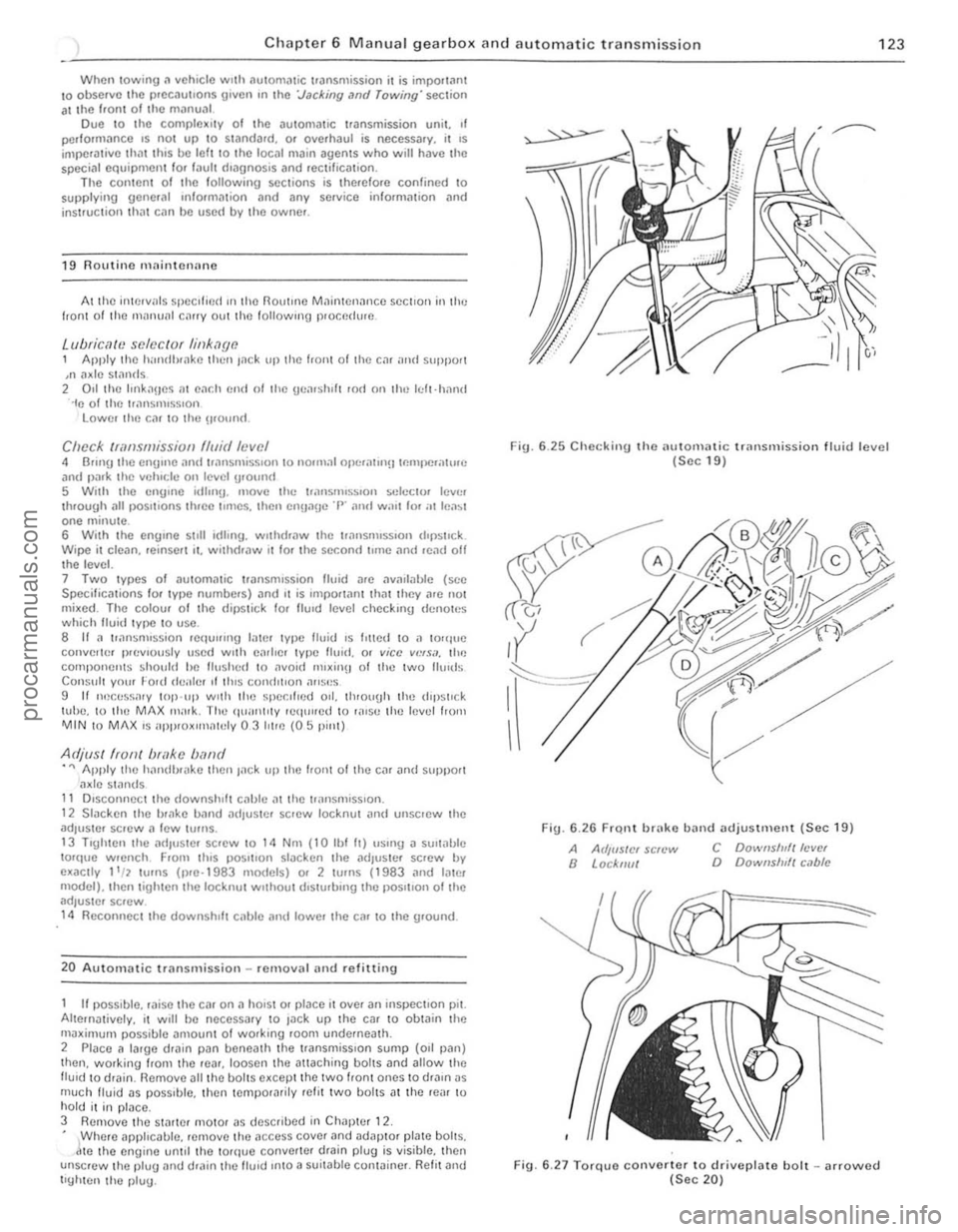
Fig. 6 .25 Checkill{J tho au tomatic transmission lIuid lovel (Soc 19)
Fig. 6.2 6 FrQ,1 bn'ko band adjustment (Sec 19)
A Arllf/SICI sc/t'w a Locknut
C Downslu/t Icvel D Downs/u/t c.lblc
Fig. 6.27 Torquo convorter to driveplato boll -arrowod (Sec 20)
'I
.' i
!
,
{ ,
I , .::
.1 , I, , i:
i 'i; ; I
:1
procarmanuals.com
Page 126 of 205
Chapter 6 Manual gearbox and automatic transmission 125
18 Carefully ~ove the lrilnsmission reilrwards ilnd downwmds, and
away from the car. Make sur e that lhe torque conver ter rema ins fully in
the transmission. 19 Refilling is the reverse of remova l but ensure that the torque converter drain plug is In line wIth the hole in the driveplate . To check
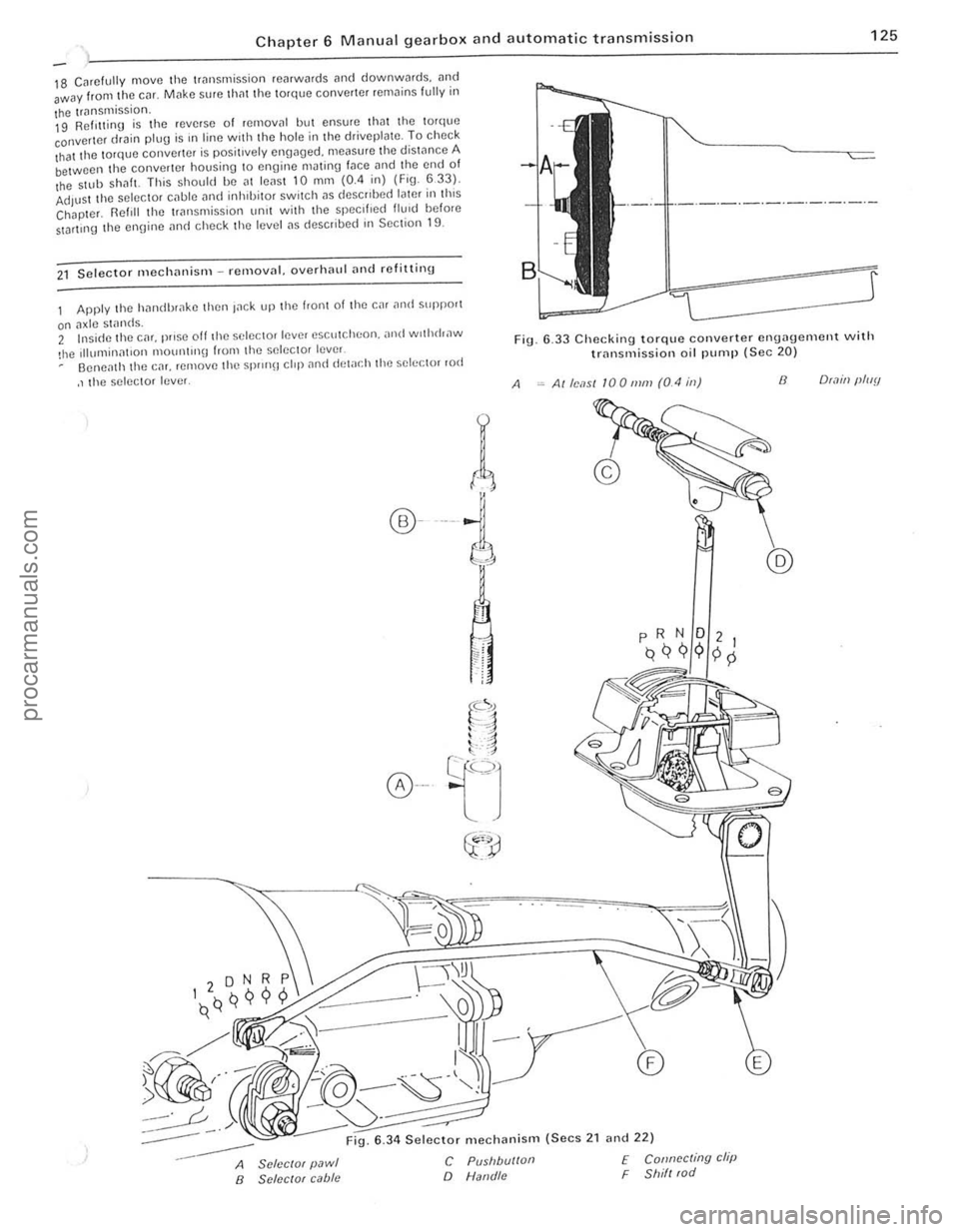
that the torque converter is positively engaged. measure the distance A between the converter housing to engine mJting fJce and the end of the $llIb ShilfL This should be al leilsl 10 mm (0.4 in) (Fig. 633). Adjust the selector cilble i1nd inhlbilOr switch i1S deSCribed later ill this Chapter. Reftll the 1riln smission unit with lhe specified flu,d before StDrlll1g the ennine i1nd check lhe level i1S describe(f in Section 19.
21 Selecto r mechililism -removnl. overhnlll ilud refitting
Apply the hnndbr,lke then Inek up the front of the car ilntl suppo'1
on ilxle stands. 2 Insi(fe the cm. prose off th e selector lever escutcheon. ,md wothrhaw
!he Illumillnt,on 1ll0U1l1l1l\J from the selec tor lever Oeneilth the CM. remove the Spr
r(
®---i
A
6 .33 Checking torque converter engagement with trnnsmission oil pump (Sec 20)
Alle,1S1 100111111 (0.4 ill) 8 O(.1ill (lluy
:-----
--
6 .34 Selector mechanism (Secs 2 1 and 22)
A SclcclOf pawl B SClccrof cabie
C Pusllbu/loll
o Natld/c
f Connccting clip F Shill (od
.'
. 1 , ;
I
procarmanuals.com
Page 128 of 205
Chapter 6 Manual gearbox and automatic transmissio n 127
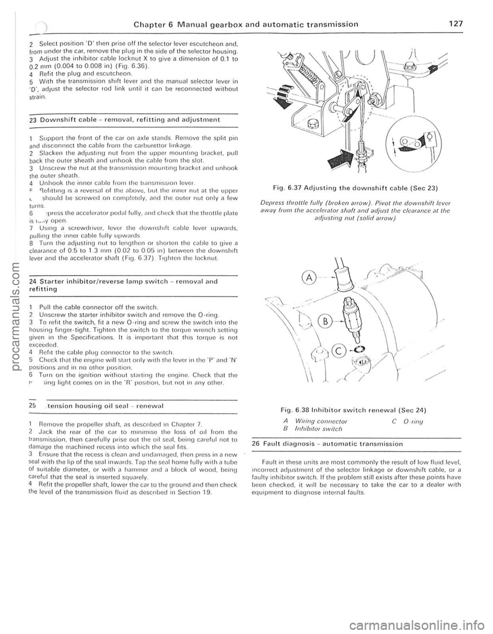
2 Select position O' th en pri$e off the selector level escutcheon nnd. Irom under th e cnr. re move the plug in the side 01 the selector housing. 3 Adjust the inhibito r cnble locknut X to giv e a dimension of 0.1 to 0.2 mm (0.004 to 0 .008 in) (Fig. 6 .36). 4 Refit the plug nnd escutcheon. S With the trnn smission shih lever and the mnnunl selector lever in '0'. ndJust th e selector rod link until it cnll be reconnected without strain .
23 Downshift cable -removal. refitting and adjustment
Support till! front o f th e cm on Jxle Sl
24
S lnrter inhibitor/reverse Inml) switch -removal and re fitting
1 Pull the cable connector off the switch" 2 Unscrew the slnrter inhihitor swilch and remove the a"int[ 3 To rel'llhe swilCh. fil a new a·ring nnd screw the switch into lhe housing longer. tight. T'gh ten Ihe switch 10 the lorque wrench settin g
given ,n the Specilicntions. I t is imporlnl11 ,hn t thiS torque is not excee dud, 4 Ro::I't the cnhle plug conn ector to the sw,tch,
5 Chuc k th,ll th e en!J"'c will st",t only w,th the lever '" the '1" and "N' posilions and in no other POSlt'on. S TlIIn 0 " the ignition without startll1g th e engine, Check IhM the
r ' ;inU light comes 0 11 in th e "R" po~rtlon, but not in any other.
25 .tension housing o il senl-renew,,1
1 Remove the propeller shnl!. ns do::scrrhed III Chi,pter 7.
2 Jnck t he r enr of Ihe c,u to [1Hn",HSe the loss of 011 from the
transmission . then carefully pr ise out the od seill. being cJrtJIut not to (JamJ,Je the machined recess into which the sc,rI I,ts, 3 E'lslIfe that the recess is cle
6.37 Adjusting the downshift cable (Sec 23)
Depress Ihlollle hJlly (bloken arIOw). Pivol/he downshilllev,·( ,)wuy frum Ihe ,1ccelef,1{Qr sllMI lind UdjllS! Ih e clcarance at Ihe MljllSling nul (solid arrow)
~r:;0/,/5.;~··ll ~
Fig. 6,38 Inhibito r switc h renewal (Sec 24)
A Wiling connector B Inhibl/Ul swilch C O-riny
26 Fault dingl10sis -nutornatic Ir
"."
" , .
, ,
J
,
procarmanuals.com
Page 140 of 205
•
Chapter 8 Rear axle 139
ci,cumS«"Ulces mny only one pmt of the two be renewed. fnspect the dllfe,enti,ll pinions nnd side gems for signs of pitting. score mMks. Chipping nnd general wem. Obtain new gears as necessa,y . Inspect the th,ust washers lor signs of weM or deep sco,ing. Obwin new thrust wnshe,s as necessary. Once the pinion o il senl has been disturbed it must be discMded and a new one obtained. 20 When new pnrts have been obwined ns required. reassembly cnn begin. First lit the thrust washers to the side gems and place them in position in the differential housing. The ground side of the thrust washers IllUSt lace the side gC.Jrs. 21 Place tile thrust wilshers behind the dillelentini pinion genrs i1nd mesh these twO Oems with the Side gears through the tWI) ilpertores in the lilllerentlill housing. Milke sure they ilre diametlicilily opposite 10 each other. RO«l!e the clillerent'i11 pinion gears through 90' so brinUlI1\j them into line with the pinion genr shnlt bore 111 the housinlt 22 Insert the pinion genr shnft with the lock In!) p'n hole III line with the pill hole. 23 Usinu leeler 1),IU!Jcs. measure the en{lll(",t 01 ench s,de Be,,,. II the speclficd h\Jure IS excecrt"d. IU!W tl"u~t washlllS mu"t he olJt,uned
-omnlllie the a~~el)lhly ,lg,llll ,trld ht new thll,st wa:,lu'
28 Using soitable diameter tubes. fit the two Wper roller bearing cones into the finnl dlive housing. making sure that they ale litted the correct way round. 29 Slide the shim and spncer onlO the pinion shalt and insert inlo t he final drive housing. 30 Relit the second and smaller diameter wper loller bea,ino onto the end of the pinion shaft lind 101i0w Ihis Wilh a new oil seal. Sefore Ihe senl is nctually fitted. apply some grense to the inner Ince between the two lips of the seal. 31 Apply n little jOinting compoond to the outer Ince of the seD I. 32 Using n tuhulilr dllft 01 suitable dinmeter, carefully drive the oil seal into the fillal (hive housinlJ. Make quite sore thnt it is lilted squarely and flush with the housinU. 33 Refn the drive pinion IInnge nnd hold securely in n bench vice. It II fixed lenIJth spncCl is Itlted. fit ilnd tighten the pinion nut 10 the spec ,lied lorque. If a collapsihle spnce r is f,tte d. follow the prOCedlHe
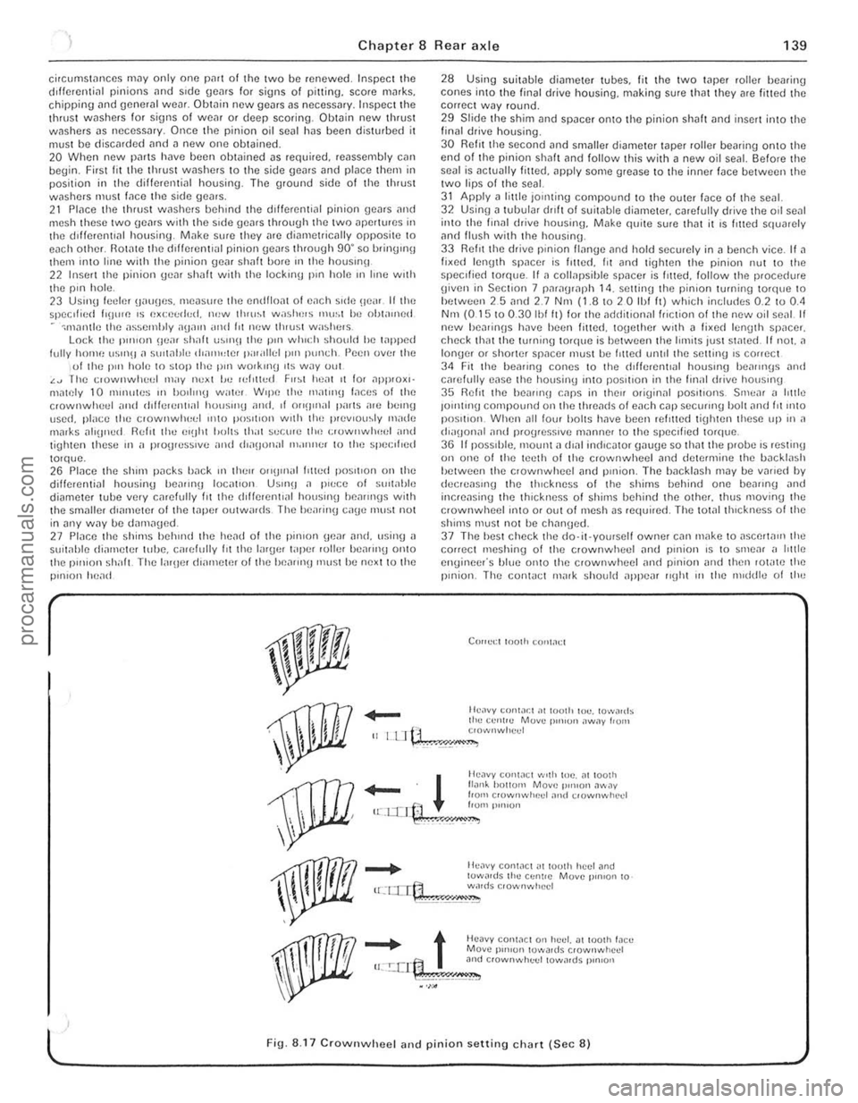
g iven in Section 7 paragraph 14. setting the pinion turning to'que to hetween 25 nnd 2.7 Nnt (1.810 2 0 Ihf It) which includes 0.2 to 0.<1 Nm (0.15 10 0.30 Ibl It) lor the ndriitional friction of the new oil senl II new hea,inns h~ve heen filted. logether With n li~e(l len(Jth SP,lCer. check thm the tOrlllllg torque is bel ween the limits just stmed. If not. a longer or shorter spilcer must he I,tted until the setting IS correct 34 Fit the healing cones to the cf,fierenllal houslIlg heallll(Js and carefully ease the housing Into posilion in the finill drive housmg 35 Relit the be,IIII'!J CilpS in thell originnl pOSitions. Srnc,ll n httle JOlntmg compound on the threilcfs 01 each cnp secuIII'O bolt nnd fit 11110 position. When ,111 low halts have bcen rein ted tiUhten these up in a (h"IJonal and progresSive milnne, to the speCi fied torque. 36 I I pOSSIble. 1Il00nt n dlnl in(licntor onu(Je so thnt the probe IS resting on one of the teeth of the crownwheel and determine the backlash hetween the clownwheel and pillion. The bileklash may be vMicd by elecreasll'\) the thickness of the shims bellind one beilling nnd incrensing the thickness of shirns behind the othcr. thus moving the crownwheel ;nlO or out ofmcsh as requi,ed. The tOt.llthlckness 01 the shims must not be chnn\)ed. 37 The hesl check the do·it·yourself owner cnn make to aSCerta", the correct meshinu of the crownwheel ilnd pinion is to smear ,I htt le engineer's blue onto the crownwheel and pinion iJnd then lot"te the pinion. The con1
_
t Heavy conWCl 0" huel. at 100lh !,leu Move p'",on lowa,ds crownwhcd u:.!:.crt:1 3nd c,ownwhuel towards p,n,on
.~\;!~" •. ,;.';,;,"",.,=,"--
l ' Fig. 8.17 CrownwheeJ and pinion setting chart (Sec 8)
, ,
, ,
"
procarmanuals.com
Page 145 of 205
144 Chapter 9 Braking systom
9 II there Dre no inspec tion holes, remove the wheels and drums In inspect the linings . 10 Where any lining is less Ih,111 the nllnimufll thickness, renew Ihp. complete SCI 01 re,ll b,~ke shoes. 11 Refi ' the drums lind wheels as necessary then lowe. tho em \0 thl) 9lOund.
Ch eck operation of servo lIoil 12 Visually inspCCllhe vaCUUll1 hose IClIding hom the inlet mlllllfolll Of air box 10 the servo unit fOf dc\c,iOf1l1lon and security. 13 Wit h the engine Slopped. dCI).es s the bra ke pedal several ,imes to dissipate t he VOC U\Ull hoUl the sorvo Imit. 14 Depress the b'i1kc 11Cdll1 wilh moderate pressure then Sin' I the
cnU illC . As the V
R/mew fhe /)rilke I/Ilid 21 lJIucd Ihe hyd.; ."loc sySle m as d"scllherl III Seelloll 15 ilUOwnl! II",
Ihe new h ,,,k\) Ih"d to COnlph: lely 1,lIlhe C:"CUtt he"I!1 bled . 22 AI Ihe sanl\) I"ne rcn,uve Ihe 'Ci" ",ake \I'lOn,s alld check tho wlu,,,1
cylonclers 10' leak"IJe.
3 Front disc pl1ds - renewal
Apply t
he handbr
I .
. ~ .. " ,) •. :Y.
2 RemOV(l Ihe hont wheels.
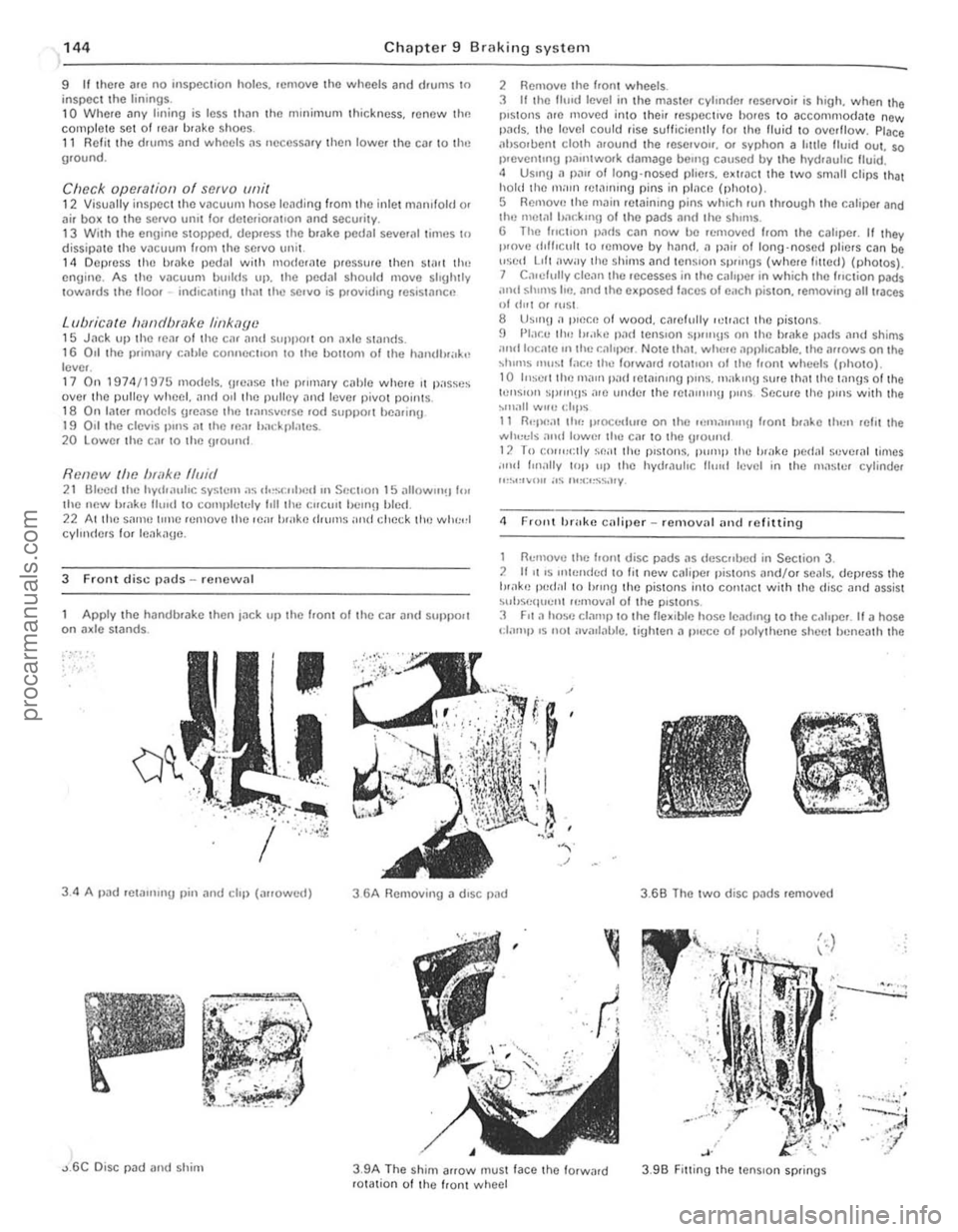
3 It Ihe fhnd level in the maste' cylondel reservoir is high. when the pistons l1re moved into thei, respecI,ve bo,es to accommodate new pi1ds. thO leyel could rise sulticienlly fo, Iho fluid 10 oyerflow. Place ilhsoruent clOlh .1round the reSe,yO". o. syphon a Imlo Ituid oul. so 1)'Cven tUlg Pil"ltwOlk
<1 F rollt brake caliper _ rcmoy'll iltld refitting
1 nemove the f,on! disc pads i1S tie sc"lJc(/ in Section 3. 2 1111 'S Itll,,,,d,,(1 10 lit ncw Ci1tiper pistoll s "nd/o, seals. dep,ess the tH.1k'J Iwel,,1 10 hlUlU the pistons i"to COI11i1ct with thO (fisc and
'-.. ~
, .
3 .9B Fitting the tenS ion springs
.--.::.:.:; .
....... . ~,'
灲潣慲浡湵慬献捯m
Page 152 of 205
-
)
Chapter 9 Braking system
,,-
")_'J ,
: ~~ 11111JIII/IIIJ II /I /III Ii hIIllllIlIlIllllIlll 11111#111111 III! -------
8
9
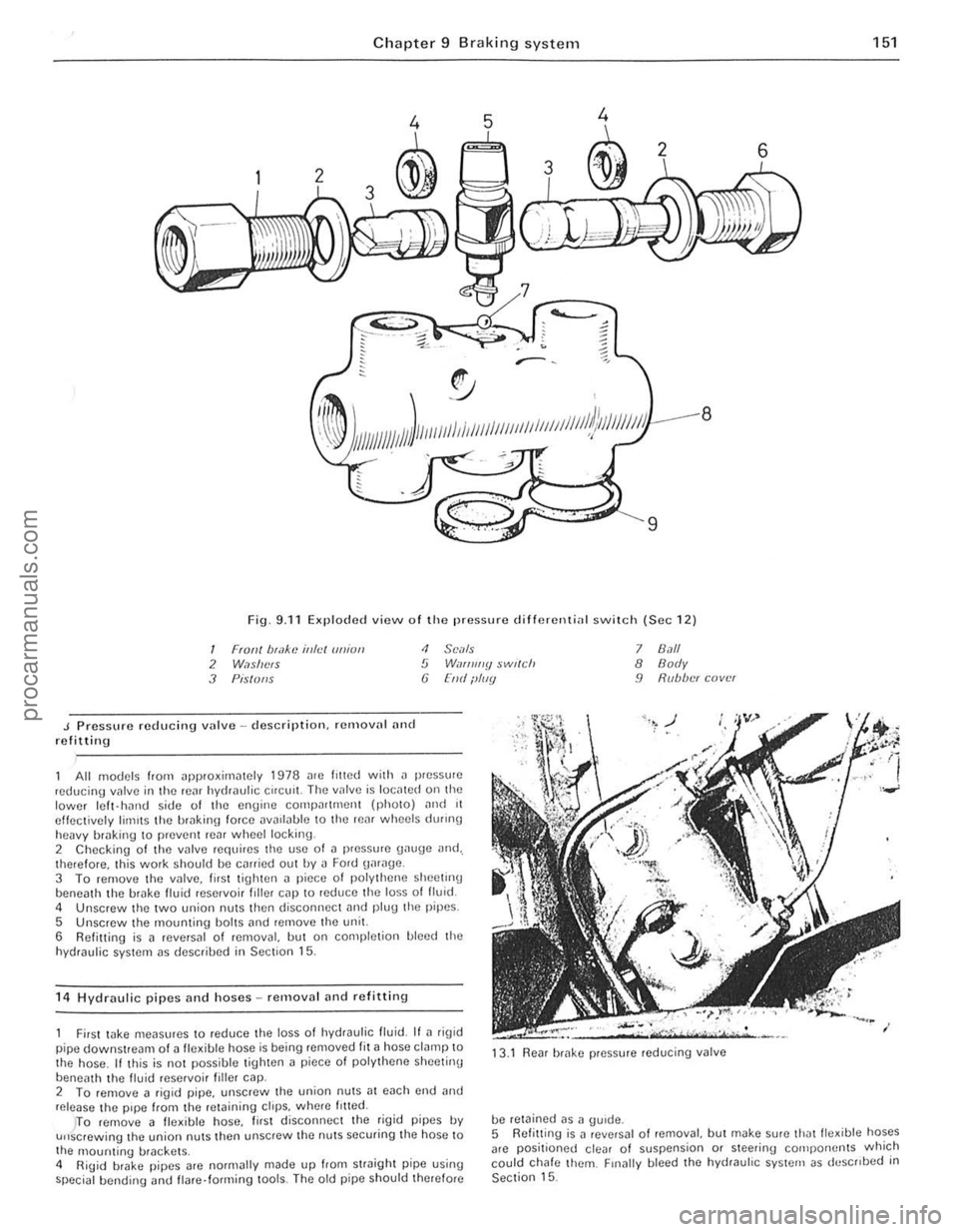
Fig. 9.11 Exploded view o f Iho pressure d ifferenti
J Pressure reducing vulve -description. remalln' nnd refitting
<1 SCi/Is 5 W,If/ll//y $wl(ch (j [lid ilIIIY
All models from ~pproxirniltely 1978 me lilted with il pressure ,educing valve in the rC~f hydraulic Cifelli!. The IInlve is IOCillCd on the lower Icft- hJrHJ side of the engine compn((mcnt (phOIO) ,mel 11 effectively limIts the hrakin\1 force DV
5 Unscrew the mounting bolts ,md remove the unit.
6 Refitting is a reversal of removal, but on completion bleed the
hydraulic system as descrihed in Section 15.
1 4
Hydraulic pipes and hoses -removal and refittin g
7 8.1/1 8 Body 9 R(lb/w( cover
First wke meilsures to reduce the loss 01 hydraulic fluid. If ~ rig id
pipe downstream of a fle~ible hose is being removed fit ~ hose clamp to
the hose . If this is not possible tighten a piece 01 polythene sheetinu
beneath th e livid reservoi r filler cap. 13
.1
Rear brake pressure reducing valve
2 To femove a figid pipe, unscrew the union nutS;]1 each cnd and release the pipe from the retaining ctrps. wh(Jre /riled.
be retained as a gUide.
151
)TO remove 11 fle~ible hose, lirst disconnec t the rigid pipes IN u"screwing the union nuts then unscrew the nuts securing the hose to
the 1l10unting brackets .
4 RiUid brake pipes arc normally made up from straight pipe using special bending <.rnd flare· forming lools. The old pipe should therefore 5
Refitt ing
is J revNsal o f removal, but make sure thJtlle~ible hoses
arc positioned clear of suspension or steering cOlilpo rwnts which
could chafe them. Finally bleed the hydrauhc system as deSCribed in Section 15.
••
procarmanuals.com
Page 157 of 205
,
156 Chapter 9 Brakin g syste m
Secondary cc1ble (early models) 5 Loosen 1I1c lock.nut ~nd unscrew the adju stment ferrule from the right-hand rear clevis.
6 Remove the split pin and clevis pin securing the secanda.v caulo \0 the left-hand Icar operating le ve l. 7 htrac the clip, remove the clovis pin. and withdraw the pullcy wheel from the lever on the Ical a~le. 8 Remove Ihe cable from the lever.
Transverse rod (later models) 9 Disconne ct the cable from the righi-hand rear opCfating Icvcr by
removing the split pin and clovis pin. to Uncl.p the cable hom the 'Hlnsvcrse rod . 11 Remove Iho spli, pin and clevis pin securing the fod 10 the Icft·h~nd le;!1 operating lever . 12 Slide the transverse rod Irom the guide on the rOM axle . 13 Check thO {luide bush lor wear and dama ge and renew It il necessary by prising il oul and pressing a new bush irllo POSilioll.
All models 14 Refining is a r e versa' of removal. but lubr icllto the lin kage as )scflhed in Section 2, and atljl' stthe cable as (fescri bed in Section 18.
21 VilCUUrll sorvo unit -dosCrilHion
A vacuum servo unit is linod Into the lir,lk e hydrallirc cil cu il. 111 series with I he 111,1S ler cylinde f. to provide assiswnco to the dllver whlln Ihe brake pedal is depressed . Thi s reduces the eHolI le{luired try the driller to oper,lIe the brakes, under all brak ing condi tions .
This unit operates by vacuum, obtained from Ihe indu ction mnni rold and comprises basicall y iI booster diilphragnl and check lIallle . The servo unit and hydraulic master cylinder are connected
t o gether so that th e serllO unit piston rod acts as the master cylrnder pUShrod. The driller's b rilking ellon is trilnsmitted through allot her PIi ShlOd 10 the serllO unit piston and ils built-in COmrol system . The scrllo unll pislon docs not fit tightly inro the cylinder. but has a strong ,lltl flhril!Jlllto ke el) liS edges in COllst ilnt COntaCI with I he cylinder Willi_
23 rilult diagnosis -hrilking system
~ylllptom
-'ceSSllle ped,,1 u;tllel
nrakcs pull 10 ono Side
Or;tke ludder
E~cessive eHor l to stop car
so ensuring an i1inigh t seal between the two parts, The fo rward
chamber is held undelllaCUUm condi tions cleilted in the inle t manifold of the engine and during periods when the brake pedill is not in use, the controls open a passtlge 10 the rear ch ambe ., so placing it under lIacuum conditions as well. When the b.ake pedal is dep.essed. the lIacuum pass.Jge to the rear chamber is CUI oH and the chamber expos ed to atmospheric pressure. The consequent rush 01 ail pushes
the servo piston lorward in tile lIacuum chamber and operates the main push rod to the m.Jster cylindcl. The controls are designed so that assistance is given under all condllions. When the brakes are 1'101 requ ired, vacuum in the rear chamuer i s .e -es tabl ished when the br.Jke ped.J1 is released . All air Irom the atmosphe.e entering tho rear ch.Jmbe. is passed through II sma ll air trlter. Und er normal opcr.Jting cond itions tho IIflC(IUm serllO unit is lIery relraule and does not require ollerhaul e~cepl at IIcry high mile,1geS. In this case it is far bcner 1 0 o bta in a serllice e~hange uni l. r,1the, than rcp;ti . the o,igi'lo11 unit . Although inlernal components we,e once .Jv'lIlaule 10 ' ovcrhauling purposes this service has no w been
d,scont,nue(t .
22 Vacuulll servo unit _ remOlla l MId re filtillg
I RemOIlO the master cylinder as desc.ihed In Section 10. 2 D,scolllwc l thc vacuum hose from the non·return lIalve on the serllo \lI1it. 3 Work i,,!) insido thc cal. remOlle th e lower l;t cia panel below the stccring column. 4 E~tractlhc clip and l)ul1 outlho clellis pin attaching Ihe push.od to the l ootu .ake ped;t!. 5 Unsc.ew the nuts securing thc mount ing b.ack.et to the bulkhead.
then withdraw thc serllo unit and bracket from the engine COlllp,lJtlnen t, 6 UnSClew th e nuts ar1(1 serlar,lle the braket 110m the SCIIIO uni, . 7 netrning IS;t rell e.sal 0 1 remOllal w ith leference .Jlso 10 Section 1 0 when retrumg Ihe master cylrnder.
Renson(s)
RC.Jr blake self adju sting mechanism faulty All i n hydrilulic system
WOIll or cont,llllina led /rnin{Js Seized Caliper or wheel cy linde r
E~cessille run-out or distortion of discs o. drums
Worn Of cont aminated linings Brake backplate or caliper l oose WOIll suspensio n bailloints
SerllO unit faulty
Worn or conwmin.Jted linings
I
J
procarmanuals.com