air condition FORD CAPRI 1974 Workshop Manual
[x] Cancel search | Manufacturer: FORD, Model Year: 1974, Model line: CAPRI, Model: FORD CAPRI 1974Pages: 205, PDF Size: 43.75 MB
Page 39 of 205
i12.
38 Chapter 1 Engine
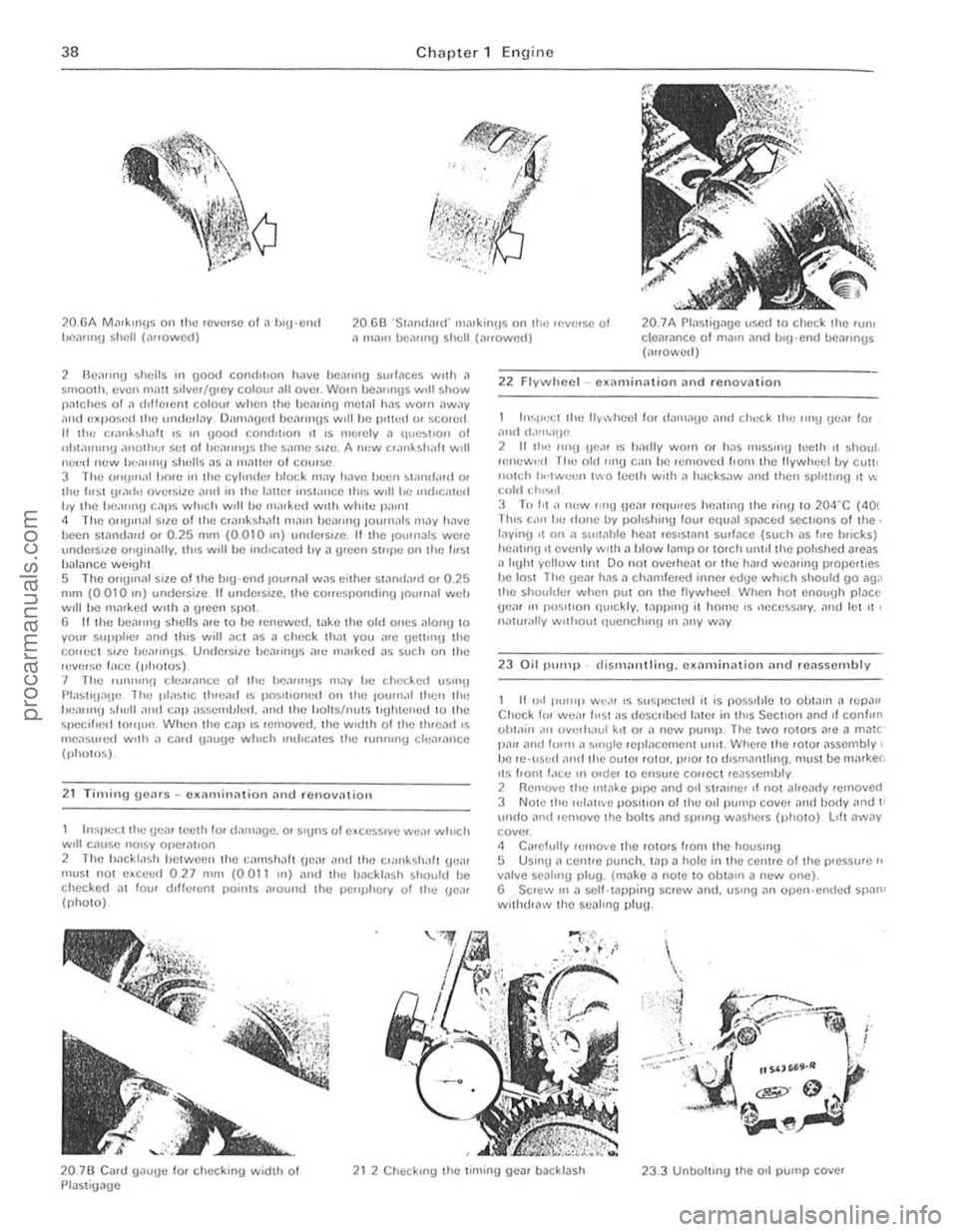
20.6A Mil,kIl1H S 011 the reverse 01 ,1 hl!1 ClI,t tlP.ilrnlH sh ell (, .... owed) 20.GEl ·S1.1n
2 BCilrll1!j shells 111 (lootl condItIon h,IVC 1)C"fU'O surfaces wllh il smooth. (lyen m.m s,tvcr /u,ey coloUI .111 ave._ Wam hCillln!IS wIll show piuches 01 il d,t(clcnt colour when the hctlring mottll h
I,,~t>(:ct Iho !)(:
hl~l)t";t Ihe lIywheel lor danln!Je and ch"ck Ih(: ling tical 10.
,1nd d.llll,I!IC 2 If th'l .1I1!1 IIC'" IS h,utiy worn Of has IllISSIl1!J It!clh II shaul. ,e!lew,·d Til" old 11111.1 call ho 'emoved Ironl tile lIywhecl by CU1\1 1l0 lc h 1I.·lwc"n two leeth With
23 Oil "ump -distl1;l!llling. cxarninntion nnd reassembly
II 011 [lU'''1> w~," IS slIspecw(l il is pOSSlhle 1 0 OOIJIIl n 'CpJII Check fVI W("" 11151 li S desc!lbed IlIte! in IhlS Sec llon ilnd II conlun vhlain ,III IIVCI "(lui kil O' il new pump_ The twO f O tors
20.7B Cil.d U
Page 97 of 205
,6 Chapter 4 Ignition system
9 The spark plug gaf} is 01 conside rable impor1~e. as. if it is too lilrge or too small. the size of the spark ilnd its efficiency will be seriously impilired. The spilrk plug should be set to the ligure given in thl} Specifications ill the beginning of this Chapter; IOTa sel it, measure the gilp with a/cere, gauge. and then bend open. or close. the outer plug electrode untillhe correct gap is achieved. The centre electrode should never be benl as this may crack the insulation ilnd cause plug fAilure if nothing worse. 11 Relit the plugs, and re/ilthe leads from the distr ibu tor in the correct I"ing order. which is given in the Specifications. Screw the plugs in by hilnd initiilily then tighten them to the specified torque using the plug spilnnel.
12 Fault diagnosis -ignition system
By lar (he nlo1jori (y 01 brCJkdown and running troubles ilre caused by InUits In the igrlOlron system er(her in (he low (enSlon or high tens ion circuns There
Engine fails 10 staft 1 If the engine falls to StM( and t he cal was IIJnning norll1t1l1y when.t wns IJst used, first check ther e is fuel in the petrol wnk. If (he engille tums ovel normally on (he starter 1I10tor and the bilHery is evidently well chmged. then the lault mny be in either the high or low tension circuits. Firs( check Ihe HT circuit. Note: If lire hal/cry is known 10 hI! {(Illy ch,}lged, Ihe ignilion liglll cOllies on, ,1I)d Ihe s/arler 1II010r {,lils /() tum IIIe ongine check the tightness o f the le'lds on the biltlely terillinilis ,1I)d <1Iso (lte seCUIIHWSS oflhe e,l,th leold (0 irs cOllllec/ion 10 tire body It is qui(e common for tlie le,1(ls /0 Ii,}ve wOlked loose. l.'vc'1I If Ihey look ,1n(/ lecl seclI,e. /I one 01 the boll/my ((:{minM {Josts [11.'1.1' vC'IV liot wi".." (Iyiny (0 wOlk Ihe s/mler 1II0tOl (his is ;/ sUie IIId'C,7/IUI/ 0/ ;/ I;wlty COllllel;('On 1(1 1h.11Ie"lIillal. 2 One of tile commonest rOilsons lor bad stmtln!J IS wet or d;UllP sp,uk plug lead~ and dlstribu(or. Hemove (he distllblltor cap. H "JOdenSil(Ion is v iSIble IIlte!llillly dry the CJp With il rag and also wIpe ;lCf the leads nelu the cap_ 3 If (he enUiue sull fmls 1 0 St.l.t. check that cunent IS reachlllg (he JUS, by dlscounectln!1 ench plug le,l<1 in turn ilt the sp1Hk plllU end, .. ,ld holdlllg Ihe end olthe callie about 5 mm (0.2 Ill) aWilY from the cylillder block. Spin the enu'ne all the sta rter motor. 1 Spa,klllg between the end of the cable ilnd Ihe block should he fa"ly strong With J strong leuulm blue spark_ (Hold (he lead WI(h wbber to ilvold elec(IIc shocks) If Clluelll is reilching (he plugs. then rel110Ve them and clean and reg,lp them. Tho engine should now SWrt 5 If there is no spilrk ilt the plug leilds. wke of! the HT lead from the cenlre of the d'sltibutor C
Engine misfires 10 If the enOlnr. mlsfues re!Julariy. run It ilt a f~st irllrng speed. Pull off eilch 01 the plu(! C,lpS III hUll nnd hsten t o (he note 01 the engrne. Hold the phl(J cnp In il dry cloth or with a rubber g love
(,J) The cOllm.lV be {,lufly giving ,111 iniNmil/elll mislile (b) Thele limy he ,1 (/iJmiJged wile or loose cOrlflee/ioll in till! low (eflsion circuil (c) The condensel /II,lY I;e shOll circuiling (i{ filled) (d) There nwy be a meehanic,lllolUI! IiI Ihe dis/flbll/or (bfOken dliving spindle or eOlllac/bleaker spring. if filled)
17 If the ignition (iming is too far reto1lded, it should be noted thallhe engine will tend to overheat. and there will he a quite no(iceable drop in powel. If the engine is overheating and Ihe power is down, and Ihe ,oni(ion tim in!) is correct. then Ihe carburenor or fuel injection should be checked, i1S ,I is likely that this is where the Iilult lies.
procarmanuals.com
Page 148 of 205
Chapter 9 Braking system 147
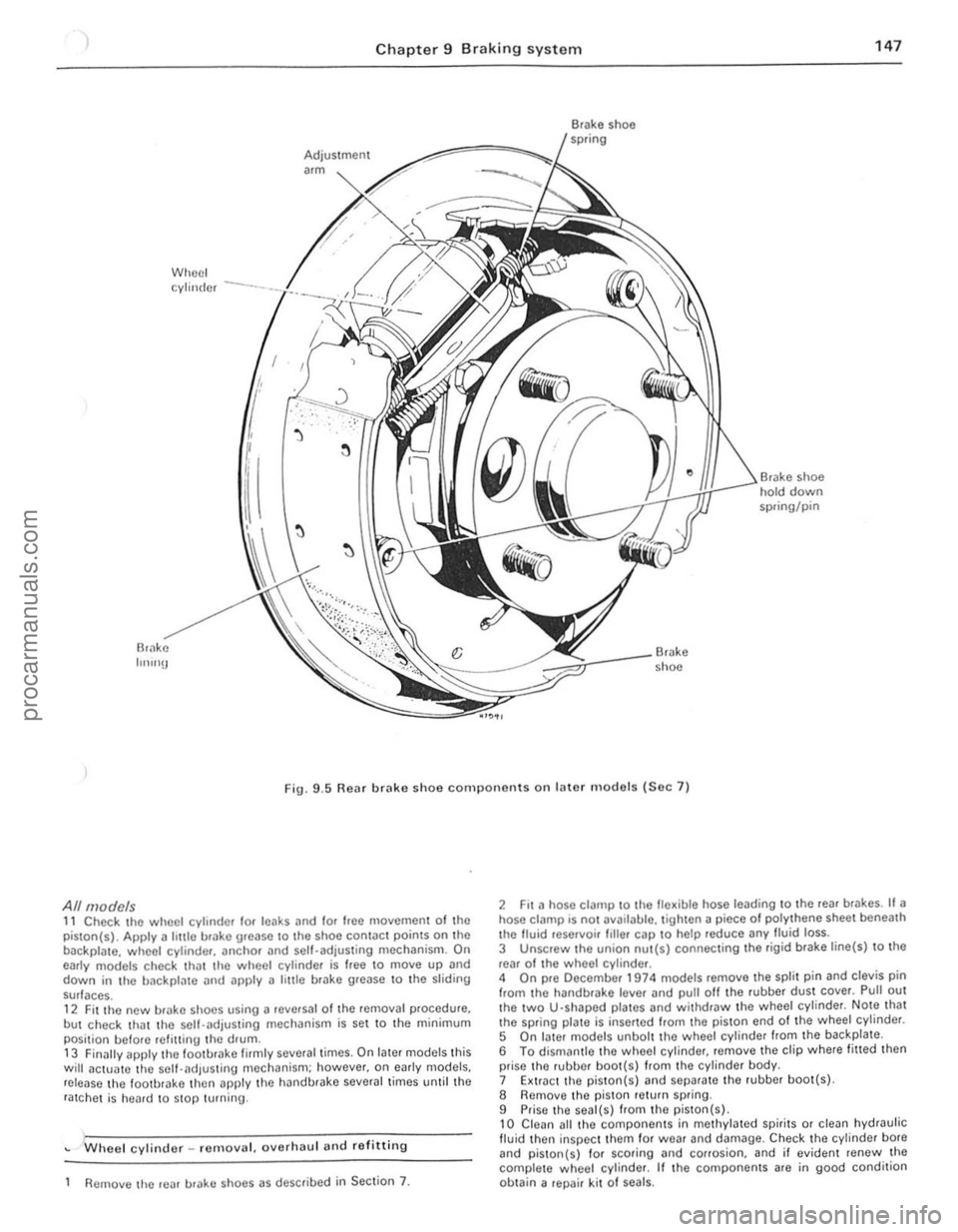
Br;'lke IlIlInU
Wheel Adjustment
"m
cylinder --·-·_.L
-::'~~:.J/
I
'j
~
l
~
• shoe hold down spring/pin
Br.lke shoe
Fig. 9
.5 Rear brake shoe components on later m odels (Sec 7)
All models 11 Check the wheel cylinder lor leaks and lor Ioee moyemen t of the
piston(s). Apply a hule brake urease to Ihe shoe contac t points on the
backpla te. wheel cylinde r, anchOr and sell-adjusting mechanism. On
early models check th
but check that the self-.. djusting mechanism is set to the minimum
posi tion belore refilling the drum .
13 Finilily apply lhe loo tbrake firmly several times. On later models this will actua1e the self-adjus ting mechanism; however. on e
Wheel cylinder _ remo yal. oyerhaul and re fitting
Remove lhe rear urake shoes as described in Section 7.
2 Fit a hose clalllp to the fle~ible hose leading to the reaf br .. kes. If a hose ci
5 On I.ller models unbolt the wheel cylinde r from the backplate .
6 To dismantle thO wheel cylinder, remoye the clip where fitted then
prise the rubber boo t(s) from the cylinder body.
7 Extr.lct the piston( s)
9 Prise the seal(s) from the piston(s) , 10 Clean all thO compo nents in methylated spirits or clean hydraulic fluid then inspec t them for wea r and damage. Check the cylinder bote and piston{s) 10f scoring and corrosion. and il eviden t renew the
complete w heol cylinder. If the components are in good condition
ob tain a repair kit 01 seals.
i.
i I
II
j
I ;
procarmanuals.com
Page 150 of 205
1 Chapter 9 Braki ng system 1 49
,1 M aste r cylinder -overhaul
With tho m
recuperating valvo. Oepress Ihe primll'y piston during Ihis procedure. 5 Exl.;'!ct Ihe primary and secondary pistons. IOgether wi,h their associated components. noting Ihe order of lemOlln l. H nccessary top Ihe master cylinder on a block of wood or use air pressure from il foot pUIllP through the inlel porlS. G Separate rhe primmy ,10d secondary l)is10 11S irani lha intermediilte
sprinu . Uso tho !inUe.s 10 remove tile Ulilnd seDI from the primil'Y
r""' lon .
The secondil'y piSlon assembly should ho sOfh"ated by lilting the u"mblo leaf ove , Ihe shouldered cnd 01 tho viston . Using the lingo,s.
rr 'wo the se
9 Dotach lhe villve space ,. tilking c
master cylinder on a block of wood or use air pressure from a 1001 pump through tho inlet ports. 12 Prise the seals from the pistons, nOling which way round they are lilled. then il necessary remove tho springs and seals. The prima ry
pis ton spring is retained by a screw.
Both types 13 Clean all tho components in melhylated spirits or brake fluid then
inspec t them for wear and damage. Check the cylinder bore and pistons for scorinu and corrosion. and if eviden t renew the complete nI
1
2~
3~
13
1
2
3
4 5 6
7 8
R
22
21
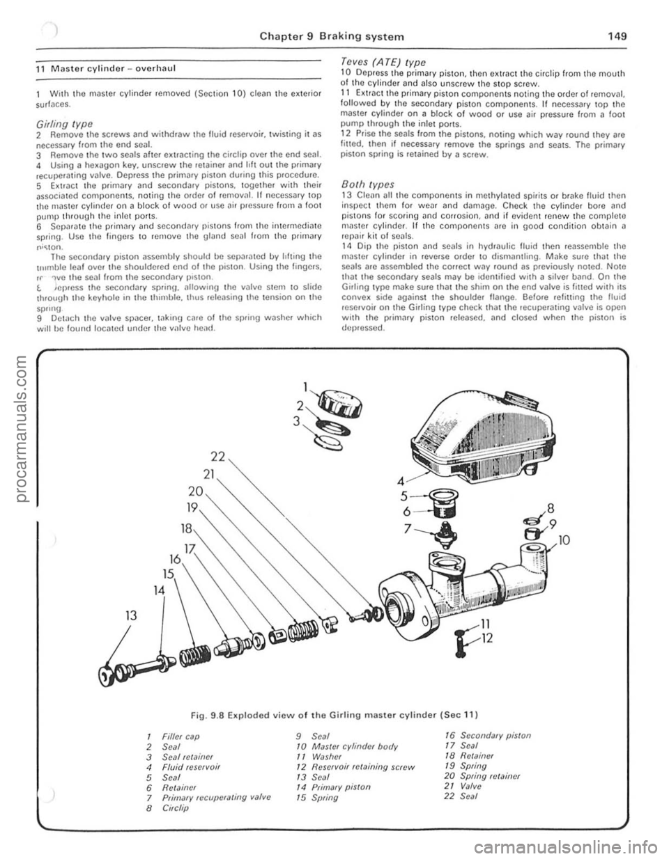
Fig. 9
.8 Exploded view 01 the Girlin g master cylinder (Sec 11)
Filler cap 9 Seal 16 Secondary piston
Seal 10 MaSler cylinder body 17 Seal
Seal !Clainer
11 WiJslrer 18 Rell11i1er
Fluid reservoi r 12 Reservoir relaining screw 19 Spring
Seal
1 3 Seal 20 Spring fl/Miner
Relainer
14 Primary piSlon 21 Valve
Primary fCCllpCfaling valve
15 Spring 22 Seal
Circlip
10
!
" 1 ,
1
I
!
!
I ,
J
,[
1
I
I
; .
!I ' i ;.
procarmanuals.com
Page 157 of 205
,
156 Chapter 9 Brakin g syste m
Secondary cc1ble (early models) 5 Loosen 1I1c lock.nut ~nd unscrew the adju stment ferrule from the right-hand rear clevis.
6 Remove the split pin and clevis pin securing the secanda.v caulo \0 the left-hand Icar operating le ve l. 7 htrac the clip, remove the clovis pin. and withdraw the pullcy wheel from the lever on the Ical a~le. 8 Remove Ihe cable from the lever.
Transverse rod (later models) 9 Disconne ct the cable from the righi-hand rear opCfating Icvcr by
removing the split pin and clovis pin. to Uncl.p the cable hom the 'Hlnsvcrse rod . 11 Remove Iho spli, pin and clevis pin securing the fod 10 the Icft·h~nd le;!1 operating lever . 12 Slide the transverse rod Irom the guide on the rOM axle . 13 Check thO {luide bush lor wear and dama ge and renew It il necessary by prising il oul and pressing a new bush irllo POSilioll.
All models 14 Refining is a r e versa' of removal. but lubr icllto the lin kage as )scflhed in Section 2, and atljl' stthe cable as (fescri bed in Section 18.
21 VilCUUrll sorvo unit -dosCrilHion
A vacuum servo unit is linod Into the lir,lk e hydrallirc cil cu il. 111 series with I he 111,1S ler cylinde f. to provide assiswnco to the dllver whlln Ihe brake pedal is depressed . Thi s reduces the eHolI le{luired try the driller to oper,lIe the brakes, under all brak ing condi tions .
This unit operates by vacuum, obtained from Ihe indu ction mnni rold and comprises basicall y iI booster diilphragnl and check lIallle . The servo unit and hydraulic master cylinder are connected
t o gether so that th e serllO unit piston rod acts as the master cylrnder pUShrod. The driller's b rilking ellon is trilnsmitted through allot her PIi ShlOd 10 the serllO unit piston and ils built-in COmrol system . The scrllo unll pislon docs not fit tightly inro the cylinder. but has a strong ,lltl flhril!Jlllto ke el) liS edges in COllst ilnt COntaCI with I he cylinder Willi_
23 rilult diagnosis -hrilking system
~ylllptom
-'ceSSllle ped,,1 u;tllel
nrakcs pull 10 ono Side
Or;tke ludder
E~cessive eHor l to stop car
so ensuring an i1inigh t seal between the two parts, The fo rward
chamber is held undelllaCUUm condi tions cleilted in the inle t manifold of the engine and during periods when the brake pedill is not in use, the controls open a passtlge 10 the rear ch ambe ., so placing it under lIacuum conditions as well. When the b.ake pedal is dep.essed. the lIacuum pass.Jge to the rear chamber is CUI oH and the chamber expos ed to atmospheric pressure. The consequent rush 01 ail pushes
the servo piston lorward in tile lIacuum chamber and operates the main push rod to the m.Jster cylindcl. The controls are designed so that assistance is given under all condllions. When the brakes are 1'101 requ ired, vacuum in the rear chamuer i s .e -es tabl ished when the br.Jke ped.J1 is released . All air Irom the atmosphe.e entering tho rear ch.Jmbe. is passed through II sma ll air trlter. Und er normal opcr.Jting cond itions tho IIflC(IUm serllO unit is lIery relraule and does not require ollerhaul e~cepl at IIcry high mile,1geS. In this case it is far bcner 1 0 o bta in a serllice e~hange uni l. r,1the, than rcp;ti . the o,igi'lo11 unit . Although inlernal components we,e once .Jv'lIlaule 10 ' ovcrhauling purposes this service has no w been
d,scont,nue(t .
22 Vacuulll servo unit _ remOlla l MId re filtillg
I RemOIlO the master cylinder as desc.ihed In Section 10. 2 D,scolllwc l thc vacuum hose from the non·return lIalve on the serllo \lI1it. 3 Work i,,!) insido thc cal. remOlle th e lower l;t cia panel below the stccring column. 4 E~tractlhc clip and l)ul1 outlho clellis pin attaching Ihe push.od to the l ootu .ake ped;t!. 5 Unsc.ew the nuts securing thc mount ing b.ack.et to the bulkhead.
then withdraw thc serllo unit and bracket from the engine COlllp,lJtlnen t, 6 UnSClew th e nuts ar1(1 serlar,lle the braket 110m the SCIIIO uni, . 7 netrning IS;t rell e.sal 0 1 remOllal w ith leference .Jlso 10 Section 1 0 when retrumg Ihe master cylrnder.
Renson(s)
RC.Jr blake self adju sting mechanism faulty All i n hydrilulic system
WOIll or cont,llllina led /rnin{Js Seized Caliper or wheel cy linde r
E~cessille run-out or distortion of discs o. drums
Worn Of cont aminated linings Brake backplate or caliper l oose WOIll suspensio n bailloints
SerllO unit faulty
Worn or conwmin.Jted linings
I
J
procarmanuals.com
Page 177 of 205
)76 Chapter 11 Bodywork and fitting
General description
The body is of all-s teel welded construction with impact ilbsorbing hont Dnd rear sections . Anli-burSllocks nrc lilted 10 the doors, ilnd the
t ailgDte is supponcd by \J
AI the in1erVills speCIfIed in the Routine M"IIl\cnilnCe section in the front 0 1 the nl
Check underbody protective coatiog 5 W,th the CM supponed on i1xle stilnds. check the cond,tlon 01 the un(lelbody protcctivc coating. i1nd wherc neceSSilry clean
M,,;ntcll
Wily to remove any aCCUIllUI,lted mud whIch WIll retillll mOlslu re
Mats and C
very line culling pils te. Finally, opply wax polish. WhNe the scrotch has penctrDt(ld right through to the metill of the bodywork. causing the mowl \0 rust. iI d ifferent repa ir lechnique is
required. Remove any loosc rus t fronl the bottom 01 the scra tch with a penknile. then apply rUSI inhibiting paint 10 prevent the lormation 01 rust in Ihe future. Using n rubber or nylon appliCiltor fill the scratch with bodystopper paste. II requ ired. this paste Ciln be mixed with cellulose thinners to provide a very thin paste which is ideal for filling narrow scratches. Before t he stopper·paSI(l in the scratch hardens. wrilp il piece 01 smooth COllon rJg i1round the lOp 01 J linger. Dip the finger in cellulose thinners and then quickly sweep it i1CIOSS the surlace of the 5topper-pJste in the scratCh: this will ensure tha t the surfilce 01 the stopper,pilste is slightly hollowed. The scratch can now be p
first wsk is to pull the dent out, untrl t he affected bodywork almost
procarmanuals.com
Page 178 of 205
) Chapter 11 Bodywork and fittin g 17 7
~!t~InS its oriOin,11 sh~flC. There is lillie point in trying to restore the original s hllpe complClC ly, as the me1011 on the darnllged arca will have stretched on impact ilnd cannOl be reshaped fully !O its original contou r, II is belter to bring the level of the dellt up to 11 poin t which is aboul ~ in (3 111111) below the level 01 the surrounding bodywork . In cases whe.e the dent is very shallow anywi'lY. i, is nOI worth trying \0 pull 1 ou t 111 all, II the ull{lersidc 01 the dent is accessible. il can be hammercd oul gently from behind, using a malleI with a wooden or plastic head. WhilSt doing Ihis. hold a suitable block of wood l'flllly a{),111151 the outside 01 the panel 10 absorb the impact from the hammer blowS and thuS Il,event 11 Imge area of the bodywo.k hom being 'belled,ouf, Should tho dem be in a section of tho bodywo.k which has iI double skin or SOI1IIl other filclOr mokil1g It inaccesslhle from behind, a
dllferent technique is cillied lor, Drill severill sm;1U holes through the
mewl II1slde the i1reil (Jilrtlcul,ldy in tho deeper section, Then screw long sel1·tap~ing screws into the holes IllSt suffIcien tly for Ihem to gilln iI good purchase In the mewl. Now the Ilen t C"n he 1)lJlled out by pulllllg on the protruding headS of the screws wllh iI pnll of pliers. The no.t stilgo of the rep,lir is the .emOllill of the PilUlt from the 113Ued meil, and hom nn Inch or so of tho SurroundlilU 'SOUfl(r
Jdywork , Tills is accomplished most oilslly by usil1U a wire brush or ab'~sllle pild on " ,)owe< dflll, ~,lthou9h It Clln he done Just i1S e ively hy hnmf usmg shoots 01 1I1)'i151110 P.l,)C •. To COlll,llete the p
thorelore decide whether to renew the whole polllel (II this IS possihle) or to .ep[lir the affoctod illoa. New body Po1nols arc not ,1S expensive as mos t flCOple think and it is often (Iuicker and mo.e satislacto • .,. to fit" new t)anelthan to auempt to rellair larue n.e,1S 01 corrosion.
RenlOlifl all f,llln\Js hom the .. lIeeted a.o" cxcoptthose which Will
act ~s ,1 uu,(ie t o the oliUllwl shape 01 the (i,lIlla\je(i bodywork (ell hn,1(1lnll1l) ~h.~lIs etc). ThOll, USlnu tin snIps or ~ h"cks
d epreSSion fo r Ih c frllcr pas\(!
'll/lle hrush the aHected Me[l to 'CIilOlle tiro powdery rust from the ,ICO 01 the lelllilllllll!l lIlet,,1 P;lInl thc "flected arc" wllh lUst
IIII"I)ltll1l) p""'t. If the hilck 01 the ,usle.1 me,1 's accesSlhle treolt tillS
" delo.o frlhflU cml t
me sh. or altlflll1l1um t",Joe. AlulIll"'um 0' pl;1strc mesh IS Il.oh"bl.,. lile hest m
Aluminium wpe should be us ed lor slll ;rll 0' vCly narrow holes. Pull a picce oil tho .011 ond tri'" It to tho apIl
ove . the hole, rt C[ln be overlapped II tho thickness of one piece is
i nsufficient. Burnish down the 00ges of tho tapO With the handle 01 "
screwdrillC ' or srmllOf, to ensure that the ",po.s securely auached to the
metal undomeath .
Bodywork rCIJ<1irs -filling a"d re-sprayi"g BefOte uSlIlg thiS Seetion, soe the Sections on denl. doep scratc h.
rust holes "nd gash repai.s . M~ny types of hodyfllfer Me ~val'ahlo, but Uonerally spe~k.ng those nrOpnelOry kits which conlain 0 till of f illor paste and a tube of resin h~fdener Me best for this type of rcp,llf A wide, !ieKilJle pl
hardener carefully (follow the m"kCI's instructions on the pack) othe.wrse thO folic. Will !>tt too rill)luly or tOO Slowly . Using the
"pplicator apply the filler paste to Ihe prcpared area: draw the
applicalOr across the surfaco 01 tho IllIer to achieve the correct contour and to lovel the fillef surface. As soon /1S it contour that approxim"tes 10 thO corrOCt one is achielled, SlOp wo.kinU the pas le - il you carryon too long the pasto will becomc sticky and begin to 'pick up' on tho
app lic"tol. Continue to add thin layels of Iiller paste at twenty· minute intervals until the level of the filler is just pfoud of the surrounding bodywork Once the IllIer has hardened, excess can be removed using a met;!1 plane or IiIe. F.om then on. progressively finer grades of abrasive paper should be used. starling with a 40 grade p.oduction paper and l.nishing With 400 o."de wet·and·dry paper . Always wrap the abrasille p"pcr IIrOUlld a flat rubber, cork. or wooden block -otherwise the surfaco 01 the frller Will nOI be completely flat. DUling the smoothing of the fIller SUI face the wel·and·dry paper shoufd be periodically rinsod in walCr. ThiS will ensure thaI alle.y smooth linish is imparted 10 the frller (It th O flllni SHIIJO. At t!\l S st1lge the 'dont ' shoul(! be surrounded by a ring of bme
mowl, whIch in IUfn Should he encirclod !.Iy the finely 'feathered' edge
0 1 th e good paintwork . Rinse tho repair nrea wilh clean water, until all 01 the dust I>roduced by the rubblllu·down operation has gone. Sp."y the whole .ep.1ir a.oa with" light coat of primer -this will show UI> any ,mpcrfOChons in lhe su.face of the fll1e •. Repai. theso Iml)CdectlOIlS with frosh 1,110' paste or bodySlOpper, and onco mOte
smoOth the sUfl
he call1od out in a w".m, dry, wind loss and dus t free atmosphero. This condition can be created mtllicially II you have access to a large indoor working "reil. but rl you nre lorced to work in the open. you Will have to pick your day lIe.y ca.efully . II you a.e working indoors. dousin\J the
floor in the work mea with water will holp 10 SOllie the dust which would otherwise be in the iltmosphe.e . If the ,epai. mea is con fined to one bod.,. pilllOl, mask off tho SUffoundlflg panels; lhis Will hell) 10 minllllise tho effocts 01 a slight mis,match in lH,lint colou.s Bodywo.k hUUlUS (eU ch.omo strips. door handles Otc) Will "'SO noed to be
"';1sked ot! Use uenume fII
S ilray on t he t op CO"1. "\Jain bUlldmu ull the tluckness by usul9
sOllof1lllhlfl'"ye .s 01 p<111l!. S Ia .t spraying in theCllnlre 01 the .epair mOil and theil, USH\g a clfcular mOllon, work outwards untrlthe whole ropmr
"rea ond al>out 2 inches 01 tho surrounding origmal pallltwork IS COvered Remolle allm"sklng mnteflaf 1010 15 minutes alter spr
Plastic compOllc"ts Wllh the use 01 mo.o and more pl"stic l>ody components by the
vehrcle manufac turers (eg bumpers, spolle.s. and in some cases major
body panels). reCllilcation 01 damago to such items .hilS .t.>e<:0me a
mOller o f eHhor emruSling relhl'r wOtk to a specialist m thiS field, o. renewing complete components Rep"ir by the DIY owner is nOlleillly feaSible owing to Ihe cost of the equipmen t and materials reQui.ed for effecting such repairs. The baSIC technique inllolves making a grOOllo
atong th o hno of the crack in the plastic using a rotary hurr in a pow~r drill. The damnged pal! is then welded hack togeth er by uSing a hot "" gun to heat up nnd luse a pl
polyca.bonate. ABS, poIYllropylene) .
procarmanuals.com
Page 203 of 205
2"4 Index
",-----------------------------------------------------------------1 -
ligh\s operation check -16 w~she( fluid levels check/lop up - 16, 217, 219
engine
crankcase emission valve renewal -16, 27
fluid leaks check -16 oil i1nd filter change -16, 26 oil filler cap clClIning -16. 26 oil level check/lop up -16 1I;llvo clearances check/adjust -16. 46
exhaust system condition check -16
fuel sySlCm
removlll and relltting lldjustllble exter ior -192 interior -192
Oil pump
p
28 Iotre engine dismantling. examination and re~sselllhly -38 ref in in 9 -42 3 0 li tre englllc dismantling. eX~lllinmion ilnd reass embly .-52 [elit\lng -54 removill 50
Pedal ,1cceler,ltOr 75 bra k e · 152 clutch -101 Pisto n an d connec ting rods ref,nin\j -42. 51 Pistons and pisto n rin\js exanllna\lon ,1nd rcoova\lon 36,51 Pi sto ns. connecting rod s il11d bearin\js (3.0 litre cngine) [lmlov,11 51 Propeller shaft 128 d s, .'r/ Prop elle r shaft cenlre bcarln!J r()"l]w~1 12!J
descrip1l011 28 I"ul l (i iaunosis - 131 removat and rel,UlI1U -128 10rque wrench seHlIlgs -128 univers~1 10lllts inspection 130 Pushrods 35< 51
R
Rndi,lto r rel11ov~I, Inspcctoon, cie
Rear lamp and b ulb removal and refttling - 216 Rear number plilte lamp and bulb removal ilnd relilling -216 R ear su spension description - 158
procarmanuals.com