buttons FORD EXPEDITION 2021 User Guide
[x] Cancel search | Manufacturer: FORD, Model Year: 2021, Model line: EXPEDITION, Model: FORD EXPEDITION 2021Pages: 574, PDF Size: 8.33 MB
Page 172 of 574
Folds the right-hand third-row
seat.
C
Folds the left-hand second-row
seat.
D
Folds the second-row bench
center seat or both second-row
captain chair seats.
E
Folds the right-hand second-row
seat.
F
To return the second-row seat backrest to
the original position, rotate the seat
backrest up until it latches in the upright
position. The seat backrest clicks when it
is locked into position.
To return the third-row seat backrest to
the original position, press the
corresponding control again.
Note: If the third row seat does not
completely fold or unfold, press and hold
the seat button until the seat folds and
unfolds twice.
If the power rear seat is disabled after 10
minutes, you can enable the seat by:
• Opening any door.
• Pressing the unlock button on the key
fob.
• Pressing any keyless entry keypad
button.
• Switching the ignition on.
Folding Down the Rear Seats to the
Load Floor WARNING: To prevent possible
damage to the seat or seatbelts, make
sure that the seatbelts are not fastened
before folding the seatback. WARNING:
Do not place cargo or
any objects behind the seatback before
returning it to the original position. The third-row seats have obstacle
detection that prevents the seats from
folding or returning if they are obstructed.
Reclining the Third Row Power Seats
WARNING:
Do not recline a rear
seat on which a child restraint is
installed. Failure to follow this instruction
could reduce the effectiveness of the
child restraint.
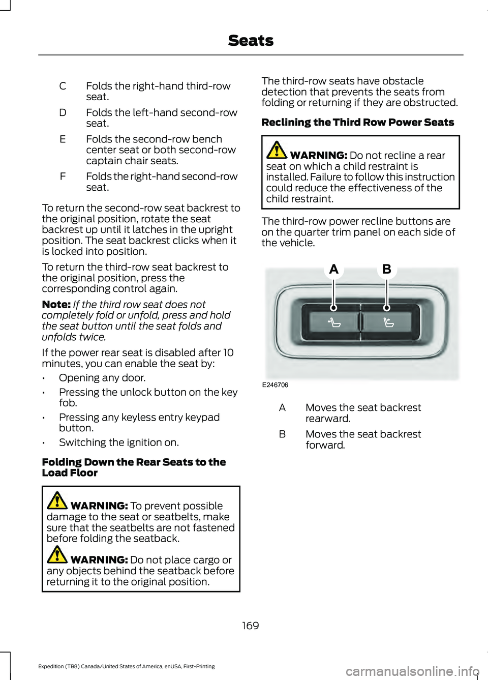
The third-row power recline buttons are
on the quarter trim panel on each side of
the vehicle. Moves the seat backrest
rearward.
A
Moves the seat backrest
forward.
B
169
Expedition (TB8) Canada/United States of America, enUSA, First-Printing SeatsE246706
Page 177 of 574
UNIVERSAL GARAGE DOOR
OPENER
HomeLink Wireless Control
System
WARNING: Do not use the system
with any garage door opener that does
not have the safety stop and reverse
feature as required by U.S. Federal
Safety Standards (this includes any
garage door opener manufactured
before April 1, 1982). A garage door
opener which cannot detect an object,
signaling the door to stop and reverse,
does not meet current federal safety
standards. Using a garage door opener
without these features increases the risk
of serious injury or death.
Note: Make sure that the garage door and
security device are free from obstruction
when you are programming. Do not program
the system with the vehicle in the garage.
Note: Make sure you keep the original
remote control transmitter for use in other
vehicles as well as for future system
programming.
Note: We recommend that upon the sale
or lease termination of your vehicle, you
erase the programmed function buttons for
security reasons. See Erasing the Function
Button Codes
later in this section.
Note: You can program a maximum of
three devices. To change or replace any of
the three devices after it has been initially
programmed, you must first erase the
current settings. See Erasing the Function
Button Codes
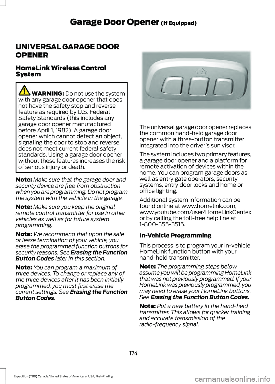
. The universal garage door opener replaces
the common hand-held garage door
opener with a three-button transmitter
integrated into the driver
’s sun visor.
The system includes two primary features,
a garage door opener and a platform for
remote activation of devices within the
home. You can program garage doors as
well as entry gate operators, security
systems, entry door locks and home or
office lighting.
Additional system information can be
found online at www.homelink.com,
www.youtube.com/user/HomeLinkGentex
or by calling the toll-free help line at
1-800-355-3515.
In-Vehicle Programming
This process is to program your in-vehicle
HomeLink function button with your
hand-held transmitter.
Note: The programming steps below
assume you will be programming HomeLink
that was not previously programmed. If your
HomeLink was previously programmed, you
may need to erase your HomeLink buttons.
See Erasing the Function Button Codes.
Note: Put a new battery in the hand-held
transmitter. This allows for quicker training
and accurate transmission of the
radio-frequency signal.
174
Expedition (TB8) Canada/United States of America, enUSA, First-Printing Garage Door Opener
(If Equipped)E188211
Page 178 of 574
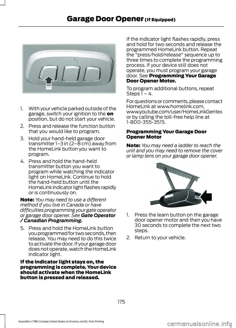
1.
With your vehicle parked outside of the
garage, switch your ignition to the on
position, but do not start your vehicle.
2. Press and release the function button that you would like to program.
3. Hold your hand-held garage door transmitter 1– 3 in (2–8 cm) away from
the HomeLink button you want to
program.
4. Press and hold the hand-held transmitter button you want to
program while watching the indicator
light on HomeLink. Continue to hold
the hand-held button until the
HomeLink indicator light flashes rapidly
or is continuously on.
Note: You may need to use a different
method if you live in Canada or have
difficulties programming your gate operator
or garage door opener. See
Gate Operator
/ Canadian Programming.
5. Press and hold the HomeLink button you programmed for two seconds, then
release. You may need to do this twice
to activate the door. If your garage door
does not operate, watch the HomeLink
indicator light.
If the indicator light stays on, the
programming is complete. Your device
should activate when the HomeLink
button is pressed and released. If the indicator light flashes rapidly, press
and hold for two seconds and release the
programmed HomeLink button. Repeat
the "press/hold/release" sequence up to
three times to complete the programming
process. If your device still does not
operate, you must program your garage
door. See
Programming Your Garage
Door Opener Motor.
To program additional buttons, repeat
Steps 1 – 4.
For questions or comments, please contact
HomeLink at www.homelink.com,
www.youtube.com/user/HomeLinkGentex
or by calling the toll-free help line at
1-800-355-3515.
Programming Your Garage Door
Opener Motor
Note: You may need a ladder to reach the
unit and you may need to remove the cover
or lamp lens on your garage door opener. 1. Press the learn button on the garage
door opener motor and then you have
30 seconds to complete the next two
steps.
2. Return to your vehicle.
175
Expedition (TB8) Canada/United States of America, enUSA, First-Printing Garage Door Opener
(If Equipped)E188212 E142659
Page 179 of 574
3.
Press and hold the function button you
want to program for 2 seconds, then
release. Repeat this step. Depending
on your brand of garage door opener,
you may need to repeat this sequence
a third time.
Gate Operator / Canadian
Programming
Canadian radio-frequency laws require
transmitter signals to “time-out” (or quit)
after several seconds of transmission –
which may not be long enough for
HomeLink to pick up the signal during
programming. Similar to this Canadian law,
some U.S. gate operators are designed to
“time-out” in the same manner.
Note: If programming a garage door opener
or gate operator, it is advised to unplug the
device during the “cycling” process to
prevent possible overheating.
1. Press and release, every two seconds,
your hand-held transmitter until the
HomeLink indicator light changes to a
rapidly blinking or continuously on light.
2. Release the hand-held transmitter button.
3. Continue programing HomeLink. See In-Vehicle Programming, Step 4.
Erasing the Function Button Codes
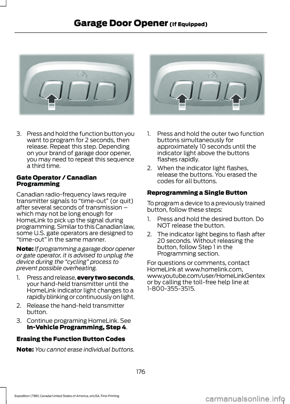
Note: You cannot erase individual buttons. 1. Press and hold the outer two function
buttons simultaneously for
approximately 10 seconds until the
indicator light above the buttons
flashes rapidly.
2. When the indicator light flashes, release the buttons. You erased the
codes for all buttons.
Reprogramming a Single Button
To program a device to a previously trained
button, follow these steps:
1. Press and hold the desired button. Do NOT release the button.
2. The indicator light begins to flash after
20 seconds. Without releasing the
button, follow Step 1 in the
Programming section.
For questions or comments, contact
HomeLink at www.homelink.com,
www.youtube.com/user/HomeLinkGentex
or by calling the toll-free help line at
1-800-355-3515.
176
Expedition (TB8) Canada/United States of America, enUSA, First-Printing Garage Door Opener
(If Equipped)E188212 E188213
Page 209 of 574
WARNING: When doing this
procedure, you need to take the
transmission out of park (P) which
means your vehicle can roll freely. To
avoid unwanted vehicle movement,
always fully apply the parking brake prior
to doing this procedure. Use wheels
chocks if appropriate.
1. Do not press the brake pedal. Press the
Start/Stop button.
2. Fully press down on the brake pedal. Keep the brakes applied through step
6.
3. Press the accelerator pedal to the floor
and hold through step 6.
4. Rotate transmission selector to Neutral
(N) and press the manual (M) button.
5. Press and release the push to start button, the transmission needs a
minimum of 2 seconds to exit park.
6. When neutral (N) displays, you can release the brake and accelerator
pedals.
To exit Stay in Neutral mode, select a
different gear.
A message appears in your information
display screen when your vehicle has
entered Stay in Neutral mode.
Drive (D)
Drive (D) is the normal driving position for
the best fuel economy. The overdrive
function allows automatic upshifts and
downshifts through gears one through ten. Manual (M)
With the transmission selector in manual
(M) or by placing the shifter column into
the manual position, you can change gears
up or down as preferred. By pushing the
manual (M) button, you have control of
selecting the gear you desire using the +
and - buttons on the transmission selector.
Tow/Haul Mode WARNING:
Do not use tow/haul
when the road surface is slippery. Failure
to follow this instruction could result in
the loss of control of your vehicle. With Column Shifter
To activate tow haul for the
column shifter, press the button
on the gearshift lever to cycle through the
available drive modes until you can select
tow haul mode.
See Drive Control (page
271). The tow haul indicator light
illuminates in the instrument cluster when
the system is active.
With Console Shifter
To activate tow haul, press the drive
modes button or rotate the dial, to cycle
through the available drive modes until you
can select tow haul mode.
See Drive
Control (page 271). The tow haul indicator
light illuminates in the instrument cluster
when the system is active.
206
Expedition (TB8) Canada/United States of America, enUSA, First-Printing TransmissionE246592
Page 211 of 574
With the transmission selector in drive (D),
push the – button to active PRS. The
available and selected gears show on the
instrument cluster.
All available gears display with the current
gear indicated. Push the – button again to
lock out gears beginning with the highest
gear. For example, push the – button twice
to lock out 10th and 9th gears. Only the
available gears display and the
transmission automatically shifts between
the available gears. Push the + button to
unlock gears and allow the transmission
to shift to higher gears. The transmission
shifts automatically within the gear range
you select.
Manual (M)
Pushing the manual (M) button on the
selector allows you to manually select the
gear you desire or by moving the shifter
column to the manual (M) position. Only
the current gear displays. Use the buttons
on the transmission selector to manually
select gears. Push the + button to upshift
or the – button to downshift. Once in
manual mode, press manual (M) again to
deactivate manual control, or place the
column in the preferred position.
SelectShift does not automatically upshift,
even if the engine is approaching the RPM
limit. Shift it manually by pushing the +
button.
Brake-Shift Interlock (Console
Shifter Only)
WARNING: When doing this
procedure, you need to take the
transmission out of park (P) which
means your vehicle can roll freely. To
avoid unwanted vehicle movement,
always fully apply the parking brake prior
to doing this procedure. Use wheels
chocks if appropriate. WARNING:
If the parking brake is
fully released, but the brake warning
lamp remains illuminated, the brakes
may not be working properly. Have your
vehicle checked as soon as possible.
Note: Do not drive your vehicle until you
verify that the brake lamps are working.
Note: See your authorized dealer as soon
as possible if you use this procedure.
Note: For some markets, this feature
disables.
Your vehicle comes with a brake-shift
interlock feature that prevents moving the
transmission from park (P) when the
ignition is in the on position and you have
not pressed the brake pedal.
If you cannot move the selector out of park
(P) with the ignition in the on position and
the brake pedal pressed, a malfunction
may have occurred. It is possible that a
fuse has blown, or your vehicle ’s brake
lamps are not operating properly. See Fuse
Specification Chart
(page 325).
If the fuse has not blown and the brake
lamps are working properly, the following
procedure allows you to move the gearshift
lever from park (P):
1. Apply the parking brake and start the engine before performing this
procedure.
2. Locate your brake-shift interlock access slot. The slot is in your center
console storage bin. The access slot
does not have a label.
208
Expedition (TB8) Canada/United States of America, enUSA, First-Printing Transmission
Page 238 of 574
If your vehicle is parked and after you
switch the ignition on, you can use the
information display to toggle through the
modes. Press the button to switch the
system on and open the system menu in
the information display.
Note:
If your vehicle is parked, the default
mode is parallel park out assist. However,
if you did not use active park assist to
parallel park your vehicle, use the
information display to select park out assist.
Note: You can repeatedly press the active
park assist button to toggle through the
modes only after moving your vehicle
approximately 33 ft (10 m).
To toggle through the modes, use the
buttons on the information display to
select the following:
• Parallel parking.
• Perpendicular parking.
• Parallel park out assist.
• Switch the system off.
Note: There is no time limit for toggling
through the modes.
Parallel Parking
The system detects available parallel
parking spaces and steers your vehicle into
the space. You control the accelerator,
gearshift and brakes. The system visually
and audibly guides you into a parallel
parking space. Press the button once to search
for a parking space.
Note: You can also switch the system on
after you have already driven partially or
completely past a parking space. Press the
active park assist button and the system
informs you if you have recently passed a
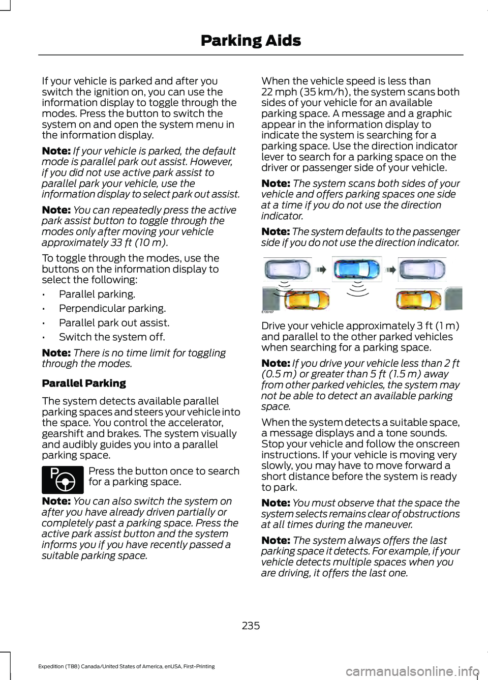
suitable parking space. When the vehicle speed is less than
22 mph (35 km/h), the system scans both
sides of your vehicle for an available
parking space. A message and a graphic
appear in the information display to
indicate the system is searching for a
parking space. Use the direction indicator
lever to search for a parking space on the
driver or passenger side of your vehicle.
Note:
The system scans both sides of your
vehicle and offers parking spaces one side
at a time if you do not use the direction
indicator.
Note: The system defaults to the passenger
side if you do not use the direction indicator. Drive your vehicle approximately 3 ft (1 m)
and parallel to the other parked vehicles
when searching for a parking space.
Note:
If you drive your vehicle less than 2 ft
(0.5 m)
or greater than 5 ft (1.5 m) away
from other parked vehicles, the system may
not be able to detect an available parking
space.
When the system detects a suitable space,
a message displays and a tone sounds.
Stop your vehicle and follow the onscreen
instructions. If your vehicle is moving very
slowly, you may have to move forward a
short distance before the system is ready
to park.
Note: You must observe that the space the
system selects remains clear of obstructions
at all times during the maneuver.
Note: The system always offers the last
parking space it detects. For example, if your
vehicle detects multiple spaces when you
are driving, it offers the last one.
235
Expedition (TB8) Canada/United States of America, enUSA, First-Printing Parking AidsE146186 E130107
Page 265 of 574
•
Trailer width measurement:
The width of the trailer is measured at the
front of the trailer. It is not measured at the
widest point of the trailer. The maximum
width at the front of the trailer that the
system can support is 8.5 ft (2.6 m).
Note: You do not need to enter an exact
trailer width measurement. You only need
to confirm that the width of the trailer is
8.5 ft (2.6 m)
or less.
• Trailer length measurement:
The trailer length is the distance between
the trailer hitch ball and the rear of the
trailer. The maximum length that the
system can support is
33 ft (10.1 m).
• Enter length of trailer:
The default setting is
18 ft (5.5 m).
Toggling up or down using the menu
buttons increases or decreases the
measurement by
3 ft (1 m). Select a length
that is equal to or within 3 ft (1 m) of the
actual measured length. For example, if
the actual measured length is 25 ft (7.6 m),
toggle the length in the menu to
27 ft
(8.2 m). When you enter the length of the
trailer, the system setup is saved.
Note: If the trailer is a bike rack or cargo
rack with electrical lighting, enter a length
of
3 ft (1 m). Cross Traffic Alert remains on
for trailers with a length of 3 ft (1 m) or less.
Note: Proper measurement and
measurement entry is required for the
system to function as designed.
System Operation
When you connect a trailer to your vehicle,
the trailer set up menu appears in the
information display. This menu allows you
to set up a new trailer or choose from a
previously set up trailer. A warning
message appears and the system turns off
if you do not choose or add a new trailer. Note:
The warning message may not
appear until your vehicle speed reaches
22 mph (35 km/h)
.
If you select a trailer in the information
display before connecting a trailer to your
vehicle, the system loads the configuration
for the selected trailer. When a trailer is
connected, a warning message appears.
Note: A second warning message may
appear stating that the Cross Traffic Alert
system has turned off. The Blind Spot
Information System with Trailer Tow
continues to function normally in this
situation.
Note: The system remembers the last
selected trailer set up when you start your
vehicle.
Trailer Considerations
The system is designed to work with a
trailer with a front width of
8.5 ft (2.6 m)
or less, and a total length from the trailer
hitch ball to the rear of the trailer of
33 ft
(10.1 m) or less.
Some trailers may cause a slight change
in system performance:
• Large box trailers may cause false
alerts to occur when driving next to
infrastructures or near parked cars. A
false alert may also occur while making
a 90 degree turn.
• Trailers that have a width greater than
8.5 ft (2.6 m)
at the front and have a
total length greater than 20 ft (6 m)
may cause delayed alerts when a
vehicle is passing at high speeds.
262
Expedition (TB8) Canada/United States of America, enUSA, First-Printing Driving Aids
Page 305 of 574
Integrated Trailer Brake Controller (If
Equipped)
WARNING: Use the integrated
trailer brake controller to properly adjust
the trailer brakes and check all
connections before towing a trailer.
Failure to follow this instruction could
result in the loss of control of your
vehicle, personal injury or death. When used properly, the trailer brake
controller assists in smooth and effective
trailer braking by powering the trailer
’s
electric or electric-over-hydraulic brakes
with a proportional output based on the
towing vehicle ’s brake pressure.
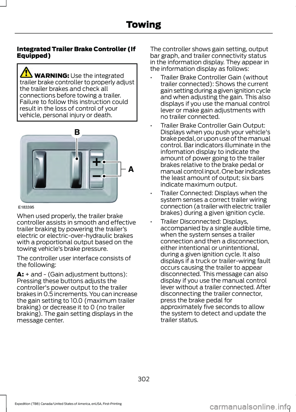
The controller user interface consists of
the following:
A:
+ and - (Gain adjustment buttons):
Pressing these buttons adjusts the
controller's power output to the trailer
brakes in 0.5 increments. You can increase
the gain setting to 10.0 (maximum trailer
braking) or decrease it to 0 (no trailer
braking). The gain setting displays in the
message center. The controller shows gain setting, output
bar graph, and trailer connectivity status
in the information display. They appear in
the information display as follows:
•
Trailer Brake Controller Gain (without
trailer connected): Shows the current
gain setting during a given ignition cycle
and when adjusting the gain. This also
displays if you use the manual control
lever or make gain adjustments with
no trailer connected.
• Trailer Brake Controller Gain Output:
Displays when you push your vehicle's
brake pedal, or upon use of the manual
control. Bar indicators illuminate in the
information display to indicate the
amount of power going to the trailer
brakes relative to the brake pedal or
manual control input. One bar indicates
the least amount of output; six bars
indicate maximum output.
• Trailer Connected: Displays when the
system senses a correct trailer wiring
connection (a trailer with electric trailer
brakes) during a given ignition cycle.
• Trailer Disconnected: Displays,
accompanied by a single audible time,
when the system senses a trailer
connection and then a disconnection,
either intentional or unintentional,
during a given ignition cycle. It also
displays if a truck or trailer-wiring fault
occurs causing the trailer to appear
disconnected. This message can also
display if you use the manual control
lever without a trailer connected. After
disconnecting the trailer connector,
press the brake pedal for
approximately five seconds to allow
the system to detect and update the
trailer status.
302
Expedition (TB8) Canada/United States of America, enUSA, First-Printing TowingE183395
Page 306 of 574
B: Manual control lever: Slide the control
lever to the left to turn on the trailer's
electric brakes independent of the tow
vehicle's. If you use the manual control
when the brake is also applied, the greater
of the two inputs determines the power
sent to the trailer brakes.
• Stop lamps: Using the manual control
lever illuminates both the trailer brake
lamps and your vehicle brake lamps
except the center high-mount stop
lamp, if you make the proper electrical
connection to the trailer. Pressing your
vehicle brake pedal also illuminates
both trailer and vehicle brake lamps.
Procedure for Adjusting Gain
Note: Only perform this procedure in a
traffic-free environment at speeds of
approximately
20– 25 mph (30–40 km/h).
The gain setting sets the trailer brake
controller for the specific towing condition.
You should change the setting as towing
conditions change. Changes to towing
conditions include trailer load, vehicle load,
road conditions and weather.
The gain should be set to provide the
maximum trailer braking assistance when
making sure the trailer wheels do not lock
when using the brakes. Locked trailer
wheels may lead to trailer instability.
1. Make sure the trailer brakes are in good
working condition, functioning normally
and properly adjusted. See your trailer
dealer if necessary.
2. Hook up the trailer and make the electrical connections according to the
trailer manufacturer's instructions.
3. When you plug in a trailer with electric or electric-over-hydraulic brakes, a
message confirming connection
appears in the information display. 4. Use the gain adjustment (+ and -)
buttons to increase or decrease the
gain setting to the desired starting
point. A gain setting of 6.0 is a good
starting point for heavier loads.
5. In a traffic-free environment, tow the trailer on a dry, level surface at a speed
of
20– 25 mph (30–40 km/h) and
squeeze the manual control lever
completely.
6. If the trailer wheels lock up, indicated by squealing tires, reduce the gain
setting. If the trailer wheels turn freely,
increase the gain setting. Repeat steps
5 and 6 until the gain setting is at a
point just below trailer wheel lock-up.
If towing a heavier trailer, trailer wheel
lock-up may not be attainable even
with the maximum gain setting of 10.
Explanation of Information Display
Warning Messages
Note: An authorized dealer can diagnose
the trailer brake controller to determine
exactly which trailer fault has occurred.
However, your warranty does not cover this
diagnosis if the fault is with the trailer.
A message indicating a trailer brake
module fault may display in response to
faults sensed by the trailer brake controller,
accompanied by a single tone. If this
message appears, contact an authorized
dealer as soon as possible for diagnosis
and repair. The controller may still
function, but performance may be
degraded.
A message indicating a trailer wiring fault
may display when there is a short circuit
on the electric brake output wire. If this
message displays, accompanied by a
single tone, with no trailer connected, the
problem is with your vehicle wiring
between the trailer brake controller and
the 7-pin connector at the bumper. If the
message only displays with a trailer
connected, the problem is with the trailer
303
Expedition (TB8) Canada/United States of America, enUSA, First-Printing Towing