FORD EXPLORER 1997 2.G Owners Manual
EXPLORER 1997 2.G
FORD
FORD
https://www.carmanualsonline.info/img/11/4954/w960_4954-0.png
FORD EXPLORER 1997 2.G Owners Manual
Trending: seat adjustment, oil temperature, washer fluid, change wheel, wheelbase, oil pressure, fuel filter
Page 151 of 236
Number Fuse Amperage
RatingCircuits Protected
13 15 amp PCM system,
stoplamps, AWD,
anti-lock brake, speed
control, trailer tow
14 10 amp Anti-lock system
15 7.5 amp Air bag system,
instrument cluster
16 30 amp Wiper run relay
17 25 amp Cigar lighter
18 15 amp A/C system
19 25 amp Ignition coil, PCM
system
20 7.5 amp Radio, power antenna,
GEM system,
anti-theft, cellular
phone
21 15 amp Turn/hazard flasher
22 10 amp Turn signals
23 10 amp Rear wiper system
24 10 amp Starter relay
25 7.5 amp Speedometer, GEM
system
26 10 amp 5R55E/4R7OW
overdrive, DRL
system, backup lamps,
AWD, rear defroster
27 10 amp Under hood lamp, map
lamps, glove box lamp,
dome lamp, visor
lamps, accessory
delay, dimmer switch
illumination, 4x4
system
Roadside emergencies
152
Page 152 of 236
Number Fuse Amperage
RatingCircuits Protected
28 7.5 amp Memory seat, GEM
system
29 10 amp Audio system
30 - Not used
31 7.5 amp Rear blower system
32 7.5 amp Heated mirror, rear
defroster
33 15 amp High beam lamps
34 7.5 amp Lux audio system
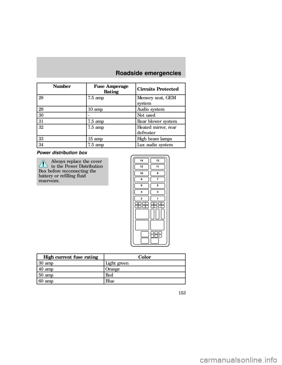
Power distribution box
Always replace the cover
to the Power Distribution
Box before reconnecting the
battery or refilling fluid
reservoirs.
High current fuse rating Color
30 amp Light green
40 amp Orange
50 amp Red
60 amp Blue
14 13
12 11
10 9
87
65
43
2
8
47
36
25
1
11 10 9
1
uno_power_distribution_box
Roadside emergencies
153
Page 153 of 236
Maxi fuses
Fuse Amperage Circuits protected
1 30 Rear window defrost
2 30 PCM power relay
3 20 Fuel system, anti-theft
system
4 20 Headlamps
5 30 ABS system
6 30 ABS system
7 20 Trailer park LP and
trailer stop LP
8 30 Battery saver relay
and headlamp relay
9 50 Blower motor
10 30 Power locks, power
windows and power
seats
11 20 PCM memory and
horn
12 50 Air ride control relay
13 60 Instrument panel fuse
panel
14 60 Ignition
Mini fuses
1 30 JBL system
2 15 Rear wiper system
3 30 Power point
4 20 4WD system
5 15 Air suspension system
6 15 Alternator system
7 10 Air bag system
8 15 DRL/Fog
lamps/Off-road lamps
9 - Not used
Roadside emergencies
154
Page 154 of 236
Maxi fuses
10 - Not used
11 20 HEGO system
Relay number Circuits connected
1 Wiper run relay
2 Horn relay
3 Wiper HI/LO relay
4 WOT A/C relay
5 PCM power relay
6 Fuel pump relay
Diode number Circuits connected
1 ABS diode
2 PCM diode
Relays
Relays are located in the power
distribution box.
Relays receive signals from
components or systems and
transfer these signals to activate or
deactivate other components or
systems.
Ford recommends that relays be
replaced by a qualified service
technician.
6
5
3
2
14 21
uno_relays
Roadside emergencies
155
Page 155 of 236
Relay number Circuits protected
1 Wiper run relay
2 Horn relay
3 Wiper HI/LO relay
4 WOT A/C relay
5 PCM power relay
6 Fuel pump relay
Diode number Circuits protected
1 ABS diode
2 PCM diode
CHANGING TIRES
Tire change procedure
1. Park on a level surface.
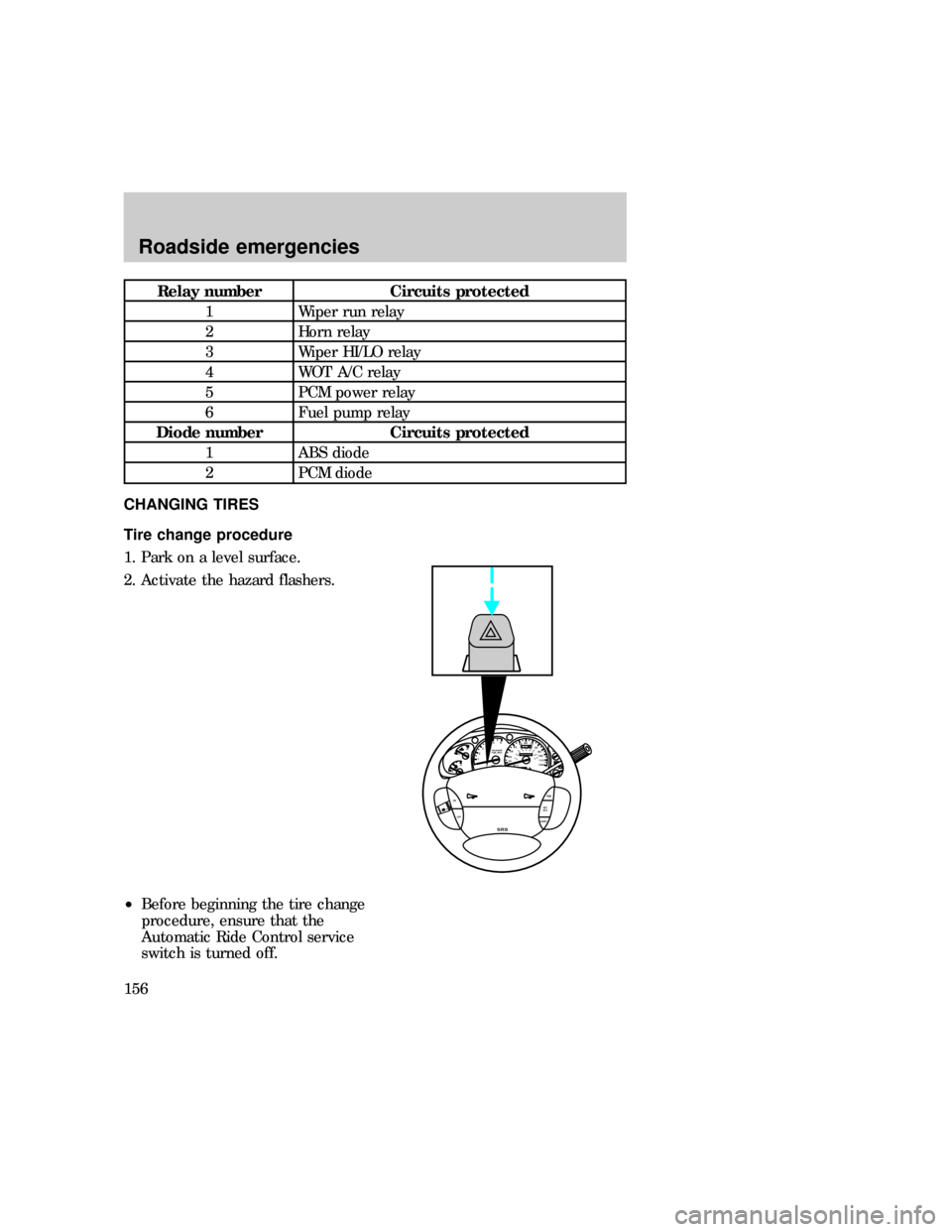
2. Activate the hazard flashers.
²Before beginning the tire change
procedure, ensure that the
Automatic Ride Control service
switch is turned off.
0P RND21
UNLEADED
FUEL ONLY
RPM x 100012345
6H
C
F
E
RSM
SET
ACC
COAST OFF ON
SRS
- +H
H
L L020
1030405060
70
80
90
110
120000000oooo
km/h10020406080100
120
140
160
180
uno_tire_change_procedure
Roadside emergencies
156
Page 156 of 236
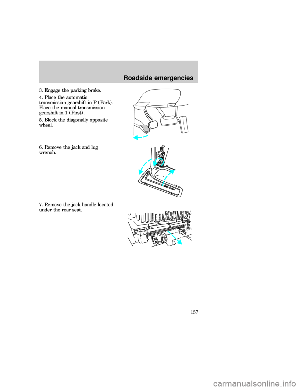
3. Engage the parking brake.
4. Place the automatic
transmission gearshift in P (Park).
Place the manual transmission
gearshift in 1 (First).
5. Block the diagonally opposite
wheel.
6. Remove the jack and lug
wrench.
7. Remove the jack handle located
under the rear seat.
Roadside emergencies
157
Page 157 of 236
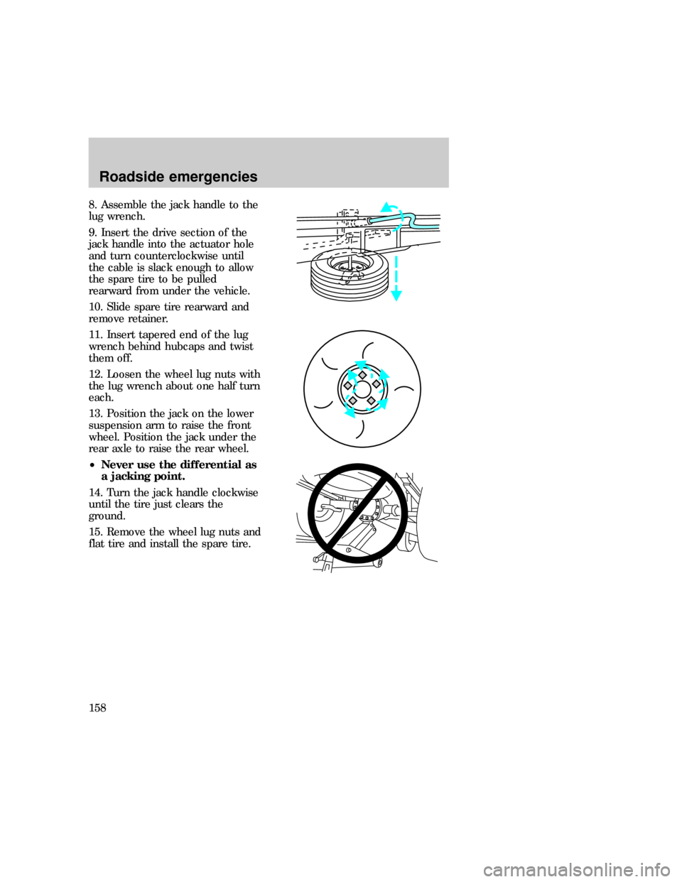
8. Assemble the jack handle to the
lug wrench.
9. Insert the drive section of the
jack handle into the actuator hole
and turn counterclockwise until
the cable is slack enough to allow
the spare tire to be pulled
rearward from under the vehicle.
10. Slide spare tire rearward and
remove retainer.
11. Insert tapered end of the lug
wrench behind hubcaps and twist
them off.
12. Loosen the wheel lug nuts with
the lug wrench about one half turn
each.
13. Position the jack on the lower
suspension arm to raise the front
wheel. Position the jack under the
rear axle to raise the rear wheel.
²Never use the differential as
a jacking point.
14. Turn the jack handle clockwise
until the tire just clears the
ground.
15. Remove the wheel lug nuts and
flat tire and install the spare tire.
Roadside emergencies
158
Page 158 of 236
16. Install the lug nuts and tighten
until snug.
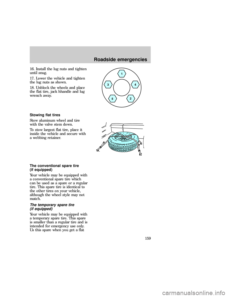
17. Lower the vehicle and tighten
the lug nuts as shown.
18. Unblock the wheels and place
the flat tire, jack hhandle and lug
wrench away.
Stowing flat tires
Stow aluminum wheel and tire
with the valve stem down.
To stow largest flat tire, place it
inside the vehicle and secure with
a webbing retainer.
The conventional spare tire
(if equipped)
Your vehicle may be equipped with
a conventional spare tire which
can be used as a spare or a regular
tire. This spare tire is identical to
the other tires on your vehicle,
although the wheel style may not
match.
The temporary spare tire
(if equipped)
Your vehicle may be equipped with
a temporary spare tire. This spare
is smaller than a regular tire and is
intended for emergency use only.
Us this spare when you get a flat
1
4
2
5 3
uno_stowing_flat_tires
uno_conventional_spare
uno_temporary_spare
Roadside emergencies
159
Page 159 of 236
tire and replace it with a full-size
tire as soon as possible.
It is not recommended that the
vehicle be operated in 4WD HIGH
or LOW modes with a temporary
spare. If 4WD HIGH or LOW
operation is necessary, do not
operate above speeds of 16 km/h
(10 mph) or for distances above 80
km (50 miles).
When driving with a temporary
spare,do not:
²exceed 80 km/h (50 mph) under
any circumstances.
²load your vehicle so that it
exceeds the maximum load
rating listed on the tire decal.
²tow a trailer.
²use tire chains on this tire.
²try to repair the temporary
spare or remove it from its
wheel.
²use the wheel for any other type
of vehicle.
²drive through an automatic car
wash.
JUMP STARTING YOUR
VEHICLE
The gases around the
battery can explode if
exposed to flames, sparks, or lit
cigarettes. An explosion could
result in injury or vehicle
damage.
com_jump-starting.01
Roadside emergencies
160
Page 160 of 236
Do not push-start your
vehicle. You could damage
the catalytic converter. For
further information, seeJumper
Cablesin the Index.
Batteries contain sulfuric
acid which burns skin,
eyes, and clothing.
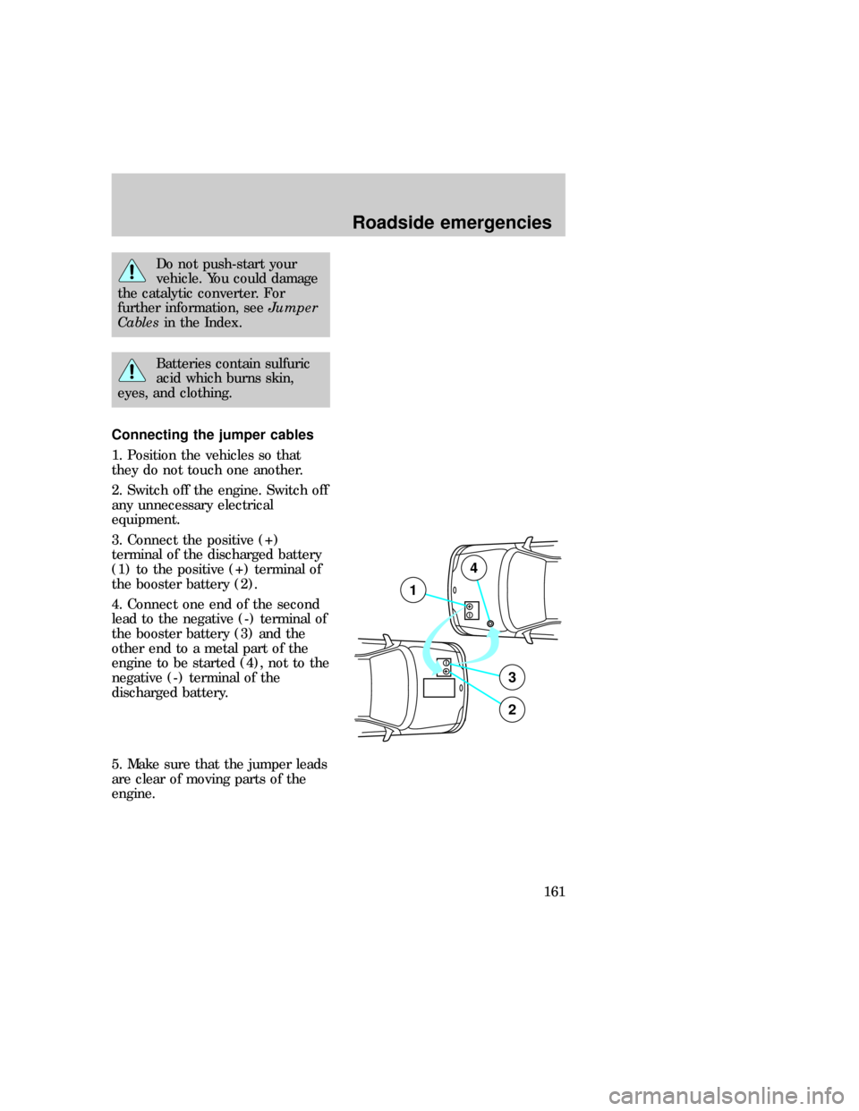
Connecting the jumper cables
1. Position the vehicles so that
they do not touch one another.
2. Switch off the engine. Switch off
any unnecessary electrical
equipment.
3. Connect the positive (+)
terminal of the discharged battery
(1) to the positive (+) terminal of
the booster battery (2).
4. Connect one end of the second
lead to the negative (-) terminal of
the booster battery (3) and the
other end to a metal part of the
engine to be started (4), not to the
negative (-) terminal of the
discharged battery.
5. Make sure that the jumper leads
are clear of moving parts of the
engine.
+–
+–
3
2
1
4
uno_connecting_cables
Roadside emergencies
161
Trending: flat tire, service indicator, AUX, transmission fluid, fold seats, inflation pressure, remote start

