transmission fluid FORD F-53 2018 Owners Manual
[x] Cancel search | Manufacturer: FORD, Model Year: 2018, Model line: F-53, Model: FORD F-53 2018Pages: 168, PDF Size: 3.02 MB
Page 5 of 168
Driving Hints
Breaking-In
......................................................54
Reduced Engine Performance .................
54
Economical Driving .......................................
54
Driving Through Water ................................
55
Roadside Emergencies
Roadside Assistance ...................................
56
Hazard Flashers ..............................................
57
Jump Starting the Vehicle ..........................
57
Transporting the Vehicle ............................
59
Customer Assistance
Getting the Services You Need .................
61
In California (U.S. Only) ..............................
62
The Better Business Bureau (BBB) Auto Line Program (U.S. Only) .......................
63
Utilizing the Mediation/Arbitration Program (Canada Only) ........................
64
Getting Assistance Outside the U.S. and Canada .........................................................
64
Ordering Additional Owner's Literature ........................................................................\
..
65
Reporting Safety Defects (U.S. Only) ........................................................................\
..
66
Reporting Safety Defects (Canada Only) ........................................................................\
..
66
Fuses
Fuse Specification Chart ...........................
68
Changing a Fuse ............................................
87
Maintenance
General Information ....................................
89
Under Hood Overview - Commercial Chassis .........................................................
89
Under Hood Overview - Motorhome Chassis .........................................................
90
Engine Oil Dipstick .........................................
91
Engine Oil Check ............................................
91
Oil Change Indicator Reset ........................
93Engine Coolant Check
.................................
93
Automatic Transmission Fluid Check ........................................................................\
...
97
Brake Fluid Check .........................................
99
Power Steering Fluid Check ....................
100
Fuel Filter .........................................................
101
Changing the 12V Battery ..........................
101
Changing the Engine Air Filter ................
103
Vehicle Care
General Information ...................................
105
Cleaning the Exterior ..................................
105
Cleaning the Engine ...................................
106
Cleaning the Wheels ..................................
106
Vehicle Storage ............................................
106
Wheels and Tires
Tire Care .........................................................
109
Using Snow Chains .....................................
124
Changing a Road Wheel ...........................
125
Technical Specifications ...........................
128
Capacities and Specifications
Engine Specifications ................................
129
Motorcraft Parts ...........................................
129
Vehicle Identification Number .................
131
Vehicle Certification Label .......................
132
Transmission Code Designation ............
132
Capacities and Specifications ................
133
Ford Protect
Ford Protect ...................................................
138
Scheduled Maintenance
General Maintenance Information .......
140
Normal Scheduled Maintenance ..........
143
Special Operating Conditions Scheduled Maintenance .............................................
145
Scheduled Maintenance Record ............
147
2
Motorhome (TY3) Canada/United States of America, enUSA, Edition date: 201712, Second Printing Table of Contents
Page 19 of 168
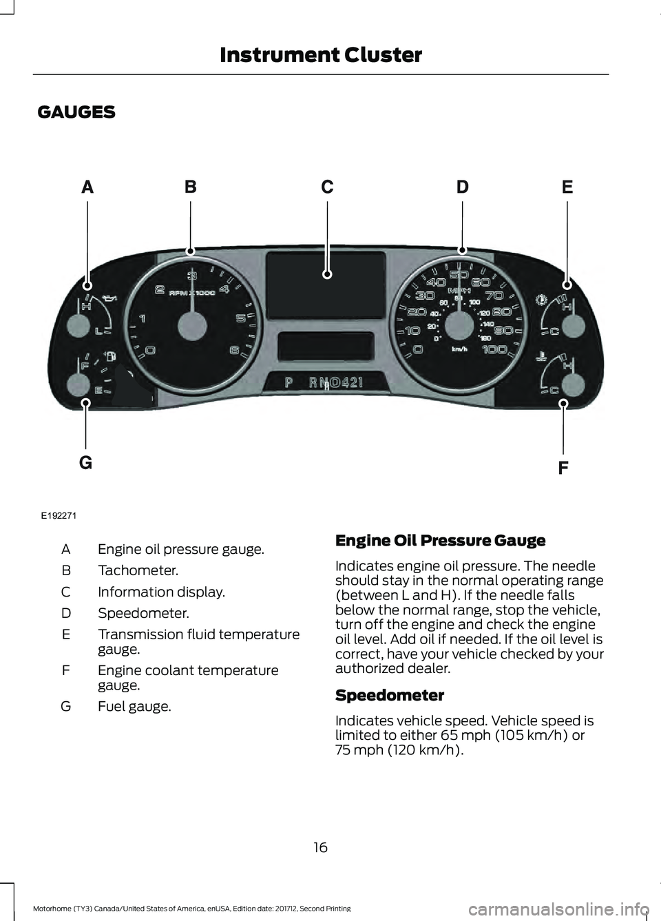
GAUGES
Engine oil pressure gauge.
A
Tachometer.
B
Information display.
C
Speedometer.
D
Transmission fluid temperature
gauge.
E
Engine coolant temperature
gauge.
F
Fuel gauge.
G Engine Oil Pressure Gauge
Indicates engine oil pressure. The needle
should stay in the normal operating range
(between L and H). If the needle falls
below the normal range, stop the vehicle,
turn off the engine and check the engine
oil level. Add oil if needed. If the oil level is
correct, have your vehicle checked by your
authorized dealer.
Speedometer
Indicates vehicle speed. Vehicle speed is
limited to either 65 mph (105 km/h) or
75 mph (120 km/h).
16
Motorhome (TY3) Canada/United States of America, enUSA, Edition date: 201712, Second Printing Instrument ClusterE192271
Page 20 of 168
Transmission Fluid Temperature
Gauge
Normal area
The transmission fluid is within the normal
operating temperature (between H and
C).
Yellow area
The transmission fluid is higher than
normal operating temperature. This can
be caused by special operation conditions
(i.e. snowplowing, towing or off-road use).
Operating the transmission for extended
periods of time with the gauge in the
yellow area may cause internal
transmission damage. Altering the severity
of the driving conditions is recommended
to lower the transmission temperature into
the normal range.
Red area
The transmission fluid is overheating. Stop
the vehicle to allow the temperature to
return to normal range.
If the gauge is operating in the yellow or
red area, stop the vehicle and verify the
airflow is not restricted such as snow or
debris blocking airflow through the grille.
If the gauge continues to show high
temperatures, see your authorized dealer.
Engine Coolant Temperature
Gauge
WARNING
Do not remove the coolant reservoir
cap when the cooling system is hot.
Wait 10 minutes for the cooling
system to cool down. Cover the coolant
reservoir cap with a thick cloth to prevent
the possibility of scalding and slowly
remove the cap. Failure to follow this
instruction could result in personal injury. At normal operating temperature, the
needle remains in the center section.
Note:
Do not restart the engine until the
cause of overheating has been resolved.
If the needle enters the red section, the
engine is overheating. Stop the engine,
switch the ignition off and determine the
cause once the engine has cooled down.
Fuel Gauge
Note: The fuel gauge may vary slightly
when your vehicle is moving or on a slope.
Switch the ignition on. The fuel gauge
indicates approximately how much fuel
you have left in the fuel tank. The arrow
adjacent to the fuel pump symbol
indicates on which side of your vehicle the
fuel filler door is located.
The needle should move toward F when
you refuel your vehicle. If the needle points
to E after adding fuel, have an authorized
dealer check the system soon.
After refueling, some variability in the
position of the needle is normal:
• It may take a short time for the needle
to reach F after leaving the gas station.
This is normal and depends upon the
slope of the pavement at the gas
station.
• The fuel amount dispensed into the
tank is a little less or more than the
gauge indicated. This is normal and
depends upon the slope of the
pavement at the gas station.
• If the gas station nozzle shuts off
before the tank is full, try a different
gas pump nozzle.
• There is a small reserve left in the tank
when the fuel gauge reaches empty.
17
Motorhome (TY3) Canada/United States of America, enUSA, Edition date: 201712, Second Printing Instrument Cluster
Page 27 of 168
Transmission
Action
Message
The transmission fluid is overheating. This warning
may appear when towing heavy loads or when driving in a low gear at a high speed for an extended period
of time. Stop your vehicle as soon as safely possible, turn off the engine and let the transmission cool.
CHECK TRANS TEMPERATURE
A reminder to apply the brakes, then shift to park.
SHIFT TO PARK
24
Motorhome (TY3) Canada/United States of America, enUSA, Edition date: 201712, Second Printing Information Displays
Page 38 of 168
Illumination of the service engine soon
indicator, charging system warning light or
the temperature warning light, fluid leaks,
strange odors, smoke or loss of engine
power could indicate that the emission
control system is not working properly.
An improperly operating or damaged
exhaust system may allow exhaust to
enter the vehicle. Have a damaged or
improperly operating exhaust system
inspected and repaired immediately.
Do not make any unauthorized changes to
your vehicle or engine. By law, vehicle
owners and anyone who manufactures,
repairs, services, sells, leases, trades
vehicles, or supervises a fleet of vehicles
are not permitted to intentionally remove
an emission control device or prevent it
from working. Information about your
vehicle
’s emission system is on the Vehicle
Emission Control Information Decal
located on or near the engine. This decal
also lists engine displacement.
Please consult your warranty information
for complete details.
On-Board Diagnostics (OBD-II)
Your vehicle has a computer known as the
on-board diagnostics system (OBD-II) that
monitors the engine ’s emission control
system. The system protects the
environment by making sure that your
vehicle continues to meet government
emission standards. The OBD-II system
also assists a service technician in properly
servicing your vehicle. When the service engine soon
indicator illuminates, the OBD-II
system has detected a
malfunction. Temporary malfunctions may
cause the service engine soon indicator to
illuminate. Examples are: 1. Your vehicle has run out of fuel
—the
engine may misfire or run poorly.
2. Poor fuel quality or water in the fuel —the engine may misfire or run
poorly.
3. The fuel fill inlet may not have closed properly. See Refueling (page 29).
4. Driving through deep water —the
electrical system may be wet.
You can correct these temporary
malfunctions by filling the fuel tank with
good quality fuel, properly closing the fuel
fill inlet or letting the electrical system dry
out. After three driving cycles without these
or any other temporary malfunctions
present, the service engine soon indicator
should stay off the next time you start the
engine. A driving cycle consists of a cold
engine startup followed by mixed city and
highway driving. No additional vehicle
service is required.
If the service engine soon indicator remains
on, have your vehicle serviced at the first
available opportunity. Although some
malfunctions detected by the OBD-II may
not have symptoms that are apparent,
continued driving with the service engine
soon indicator on can result in increased
emissions, lower fuel economy, reduced
engine and transmission smoothness and
lead to more costly repairs.
Readiness for Inspection and
Maintenance (I/M) Testing
Some state and provincial and local
governments may have
Inspection/Maintenance (I/M) programs
to inspect the emission control equipment
on your vehicle. Failure to pass this
inspection could prevent you from getting
a vehicle registration. If the service engine soon
indicator is on or the bulb does
not work, your vehicle may need
service. See On-Board Diagnostics.
35
Motorhome (TY3) Canada/United States of America, enUSA, Edition date: 201712, Second Printing Engine Emission Control
Page 43 of 168
GENERAL INFORMATION
Note:
Occasional brake noise is normal. If
a metal-to-metal, continuous grinding or
continuous squeal sound is present, the
brake linings may be worn-out and should
be inspected by an authorized dealer. If the
vehicle has continuous vibration or shudder
in the steering wheel while braking, the
vehicle should be inspected by an
authorized dealer.
Note: Brake dust may accumulate on the
wheels, even under normal driving
conditions. Some dust is inevitable as the
brakes wear and does not contribute to
brake noise. See Cleaning the Wheels
(page 106). See the Instrument Cluster
chapter for information on the
brake system warning light.
Wet brakes result in reduced braking
efficiency. Gently press the brake pedal a
few times when driving from a car wash or
standing water to dry the brakes.
Brake Over Accelerator
In the event the accelerator pedal
becomes stuck or entrapped, apply steady
and firm pressure to the brake pedal to
slow the vehicle and reduce engine power.
If you experience this condition, apply the
brakes and bring your vehicle to a safe
stop. Turn the engine off, shift the
transmission into park (P), apply the
parking brake, and then inspect the
accelerator pedal for any interferences. If
none are found and the condition persists,
have your vehicle towed to the nearest
authorized dealer. Hydraulic brake booster system
(Hydroboost or Hydromax)
The Hydroboost and Hydromax systems
receive fluid pressure from the power
steering pump to provide power assist
during braking.
The Hydromax booster receives backup
pressure from the reserve system electric
pump whenever the fluid in the power
steering system is not flowing. When the
engine is off, the pump will turn on if the
brake pedal is applied, or if the ignition is
turned to the on position.
The sound of the pump operating may be
heard by the driver, but this is a normal
characteristic of the system.
The reserve system provides reduced
braking power, so the vehicle should be
operated under these conditions with
caution, and only to seek service repair and
remove the vehicle from the roadway.
Note:
For Hydromax-equipped vehicles
operating under normal conditions, the noise
of the fluid flowing through the booster may
be heard whenever the brake is applied. This
condition is normal. Vehicle service is not
required.
If braking performance or pedal response
becomes very poor, even when the pedal
is strongly pressed, it may indicate the
presence of air in the hydraulic system or
leakage of fluid. Stop the vehicle safely as
soon as possible and seek service
immediately.
HINTS ON DRIVING WITH
ANTI-LOCK BRAKES
The anti-lock braking system does not
eliminate the risks when:
• You drive too closely to the vehicle in
front of you.
• Your vehicle is hydroplaning.
40
Motorhome (TY3) Canada/United States of America, enUSA, Edition date: 201712, Second Printing BrakesE144522
Page 93 of 168
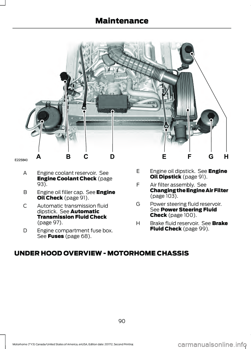
Engine coolant reservoir. See
Engine Coolant Check (page
93).
A
Engine oil filler cap. See Engine
Oil Check
(page 91).
B
Automatic transmission fluid
dipstick. See
Automatic
Transmission Fluid Check
(page
97).
C
Engine compartment fuse box.
See
Fuses (page 68).
D Engine oil dipstick. See
Engine
Oil Dipstick (page 91).
E
Air filter assembly. See
Changing the Engine Air Filter
(page
103).
F
Power steering fluid reservoir.
See
Power Steering Fluid
Check (page 100).
G
Brake fluid reservoir. See
Brake
Fluid Check (page 99).
H
UNDER HOOD OVERVIEW - MOTORHOME CHASSIS
90
Motorhome (TY3) Canada/United States of America, enUSA, Edition date: 201712, Second Printing MaintenanceE225840HGFEABCD
Page 94 of 168
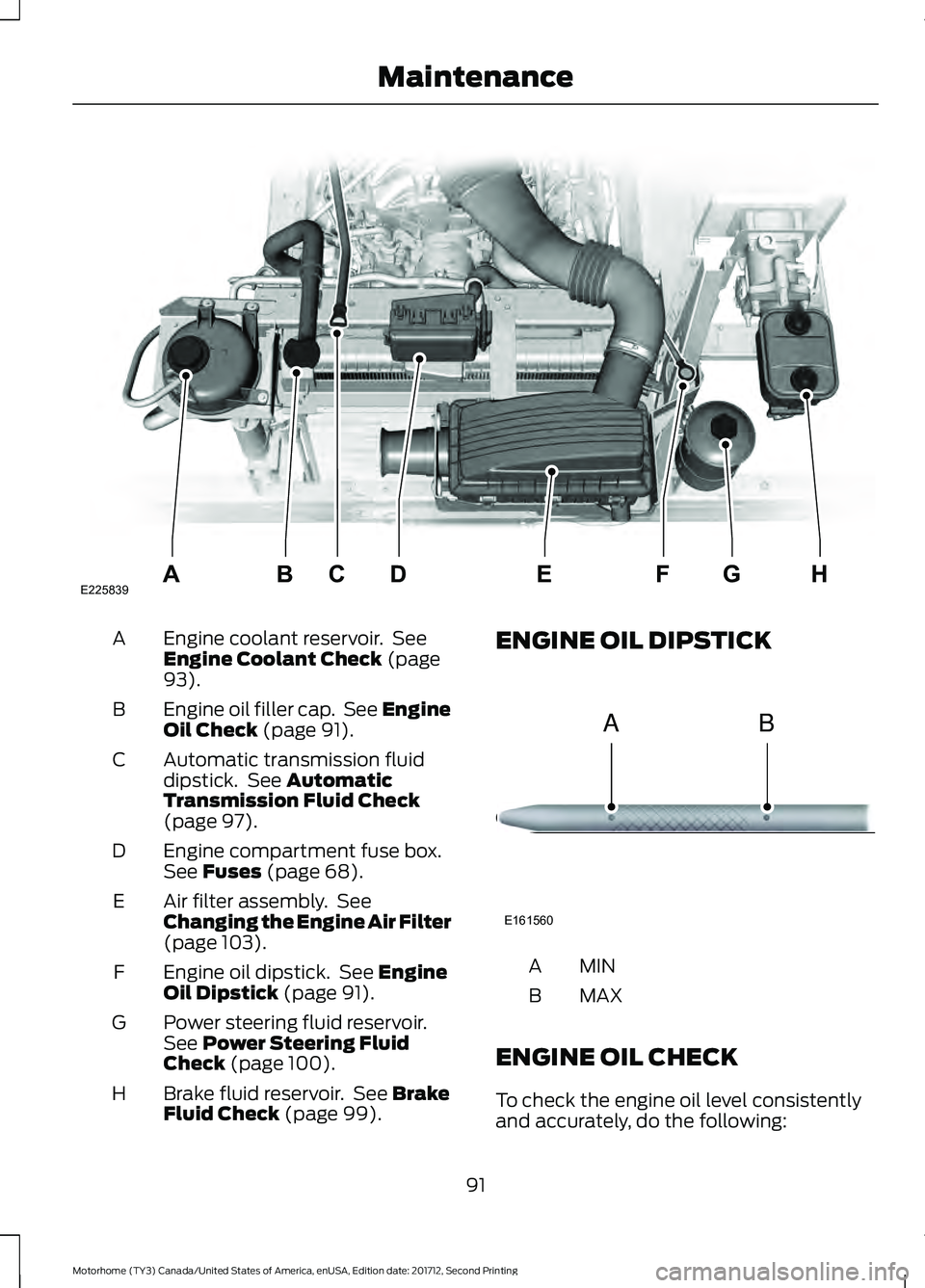
Engine coolant reservoir. See
Engine Coolant Check (page
93).
A
Engine oil filler cap. See Engine
Oil Check
(page 91).
B
Automatic transmission fluid
dipstick. See
Automatic
Transmission Fluid Check
(page
97).
C
Engine compartment fuse box.
See
Fuses (page 68).
D
Air filter assembly. See
Changing the Engine Air Filter
(page
103).
E
Engine oil dipstick. See
Engine
Oil Dipstick (page 91).
F
Power steering fluid reservoir.
See
Power Steering Fluid
Check (page 100).
G
Brake fluid reservoir. See
Brake
Fluid Check (page 99).
H ENGINE OIL DIPSTICK
MINA
MAX
B
ENGINE OIL CHECK
To check the engine oil level consistently
and accurately, do the following:
91
Motorhome (TY3) Canada/United States of America, enUSA, Edition date: 201712, Second Printing MaintenanceE225839HGFEABCD E161560
AB
Page 100 of 168
You may notice a reduction in vehicle
speed caused by reduced engine power in
order to manage the engine coolant
temperature. Your vehicle may enter this
mode if certain high-temperature and
high-load conditions take place. The
amount of speed reduction depends on
vehicle loading, grade and ambient
temperature. If this occurs, there is no
need to pull off the road. You can continue
to drive your vehicle.
The air conditioning may automatically
turn on and off during severe operating
conditions to protect the engine from
overheating. When the coolant
temperature decreases to the normal
operating temperature, the air conditioning
turns on.
If the coolant temperature gauge moves
fully into the red zone, or if the coolant
temperature warning or service engine
soon messages appear in your information
display, do the following:
1. Pull off the road as soon as safely
possible and shift the transmission into
park (P).
2. Leave the engine running until the coolant temperature gauge needle
returns to the normal position. After
several minutes, if the temperature
does not drop, follow the remaining
steps.
3. Switch the engine off and wait for it to
cool. Check the coolant level.
4. If the coolant level is at or below the minimum mark, add prediluted coolant
immediately.
5. If the coolant level is normal, restart the engine and continue. AUTOMATIC TRANSMISSION
FLUID CHECK WARNING
The dipstick cap and surrounding
components may be hot; gloves are
recommended.
Note:
Automatic transmission fluid
expands when warmed. To obtain an
accurate fluid check, drive the vehicle until
it is at normal operating temperature
(approximately 20 miles [30 km]). If your
vehicle has been operated for an extended
period at high speeds, in city traffic during
hot weather or pulling a trailer, the vehicle
should be turned off for about 30 minutes
to allow fluid to cool to normal operating
temperature 196°F - 215°F (91°C - 102°C)
before checking.
Refer to your scheduled maintenance
information for scheduled intervals for fluid
checks and changes.
Your transmission does not consume fluid.
However, the fluid level should be checked
if the transmission is not working properly,
(i.e., if the transmission slips or shifts
slowly) or if you notice some sign of fluid
leakage. To check the fluid level:
1. Drive the vehicle 20 miles (30 km) or until it reaches normal operating
temperature
2. Park the vehicle on a level surface and
engage the parking brake
3. With the engine running, parking brake
engaged and your foot on the brake
pedal, move the gearshift lever through
all of the gear ranges. Allow sufficient
time for each gear to engage
4. Latch the gearshift lever in P (Park) and leave the engine running.
97
Motorhome (TY3) Canada/United States of America, enUSA, Edition date: 201712, Second Printing Maintenance
Page 101 of 168
5. Remove the dipstick, wiping it clean
with a clean, dry lint free rag. If
necessary, refer to Under Hood
Overview in this chapter for the
location of the dipstick.
6. Install the dipstick making sure it is fully
seated in the filler tube.
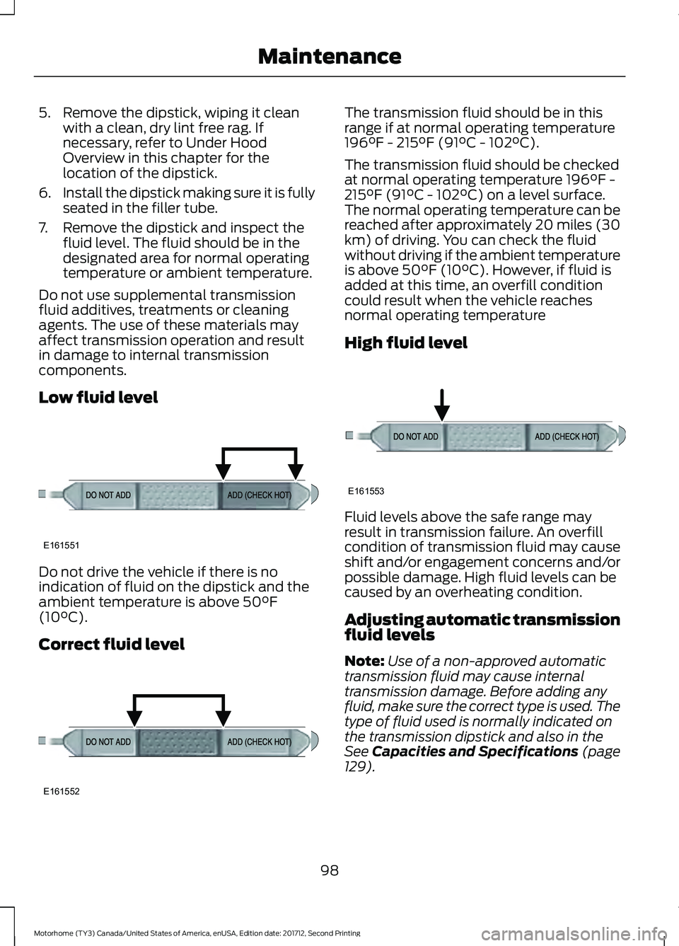
7. Remove the dipstick and inspect the fluid level. The fluid should be in the
designated area for normal operating
temperature or ambient temperature.
Do not use supplemental transmission
fluid additives, treatments or cleaning
agents. The use of these materials may
affect transmission operation and result
in damage to internal transmission
components.
Low fluid level Do not drive the vehicle if there is no
indication of fluid on the dipstick and the
ambient temperature is above 50°F
(10°C).
Correct fluid level The transmission fluid should be in this
range if at normal operating temperature
196°F - 215°F (91°C - 102°C).
The transmission fluid should be checked
at normal operating temperature 196°F -
215°F (91°C - 102°C) on a level surface.
The normal operating temperature can be
reached after approximately 20 miles (30
km) of driving. You can check the fluid
without driving if the ambient temperature
is above 50°F (10°C). However, if fluid is
added at this time, an overfill condition
could result when the vehicle reaches
normal operating temperature
High fluid level
Fluid levels above the safe range may
result in transmission failure. An overfill
condition of transmission fluid may cause
shift and/or engagement concerns and/or
possible damage. High fluid levels can be
caused by an overheating condition.
Adjusting automatic transmission
fluid levels
Note:
Use of a non-approved automatic
transmission fluid may cause internal
transmission damage. Before adding any
fluid, make sure the correct type is used. The
type of fluid used is normally indicated on
the transmission dipstick and also in the
See Capacities and Specifications (page
129).
98
Motorhome (TY3) Canada/United States of America, enUSA, Edition date: 201712, Second Printing MaintenanceE161551 E161552 E161553