park assist FORD F SERIES MOTORHOME AND COMMERCIAL CHASSIS 2001 10.G Owners Manual
[x] Cancel search | Manufacturer: FORD, Model Year: 2001, Model line: F SERIES MOTORHOME AND COMMERCIAL CHASSIS, Model: FORD F SERIES MOTORHOME AND COMMERCIAL CHASSIS 2001 10.GPages: 104, PDF Size: 1.32 MB
Page 28 of 104
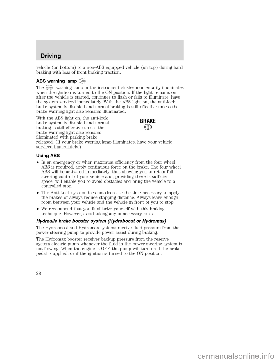
vehicle (on bottom) to a non-ABS equipped vehicle (on top) during hard
braking with loss of front braking traction.
ABS warning lamp
ABS
TheABSwarning lamp in the instrument cluster momentarily illuminates
when the ignition is turned to the ON position. If the light remains on
after the vehicle is started, continues to flash or fails to illuminate, have
the system serviced immediately. With the ABS light on, the anti-lock
brake system is disabled and normal braking is still effective unless the
brake warning light also remains illuminated.
With the ABS light on, the anti-lock
brake system is disabled and normal
braking is still effective unless the
brake warning light also remains
illuminated with parking brake
released. (If your brake warning lamp illuminates, have your vehicle
serviced immediately.)
Using ABS
•In an emergency or when maximum efficiency from the four wheel
ABS is required, apply continuous force on the brake. The four wheel
ABS will be activated immediately, thus allowing you to retain full
steering control of your vehicle and, providing there is sufficient
space, will enable you to avoid obstacles and bring the vehicle to a
controlled stop.
•The Anti-Lock system does not decrease the time necessary to apply
the brakes or always reduce stopping distance. Always leave enough
room between your vehicle and the vehicle in front of you to stop.
•We recommend that you familiarize yourself with this braking
technique. However, avoid taking any unnecessary risks.
Hydraulic brake booster system (Hydroboost or Hydromax)
The Hydroboost and Hydromax systems receive fluid pressure from the
power steering pump to provide power assist during braking.
The Hydromax booster receives backup pressure from the reserve
system electric pump whenever the fluid in the power steering system is
not flowing. When the engine is OFF, the pump will turn on if the brake
pedal is applied, or if the ignition is turned to the ON position.
Driving
28
Page 46 of 104
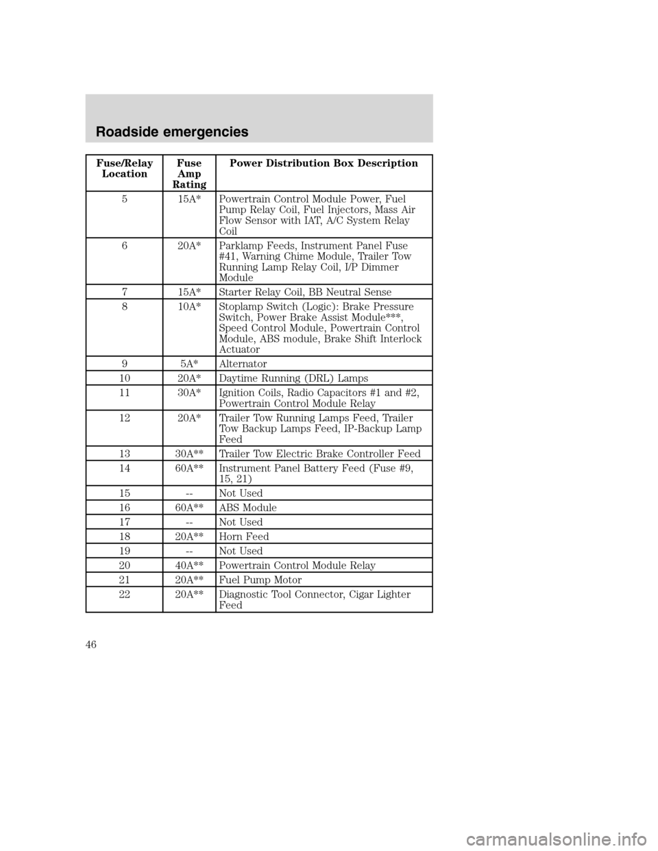
Fuse/Relay
LocationFuse
Amp
RatingPower Distribution Box Description
5 15A* Powertrain Control Module Power, Fuel
Pump Relay Coil, Fuel Injectors, Mass Air
Flow Sensor with IAT, A/C System Relay
Coil
6 20A* Parklamp Feeds, Instrument Panel Fuse
#41, Warning Chime Module, Trailer Tow
Running Lamp Relay Coil, I/P Dimmer
Module
7 15A* Starter Relay Coil, BB Neutral Sense
8 10A* Stoplamp Switch (Logic): Brake Pressure
Switch, Power Brake Assist Module***,
Speed Control Module, Powertrain Control
Module, ABS module, Brake Shift Interlock
Actuator
9 5A* Alternator
10 20A* Daytime Running (DRL) Lamps
11 30A* Ignition Coils, Radio Capacitors #1 and #2,
Powertrain Control Module Relay
12 20A* Trailer Tow Running Lamps Feed, Trailer
Tow Backup Lamps Feed, IP-Backup Lamp
Feed
13 30A** Trailer Tow Electric Brake Controller Feed
14 60A** Instrument Panel Battery Feed (Fuse #9,
15, 21)
15 -- Not Used
16 60A** ABS Module
17 -- Not Used
18 20A** Horn Feed
19 -- Not Used
20 40A** Powertrain Control Module Relay
21 20A** Fuel Pump Motor
22 20A** Diagnostic Tool Connector, Cigar Lighter
Feed
Roadside emergencies
46
Page 47 of 104
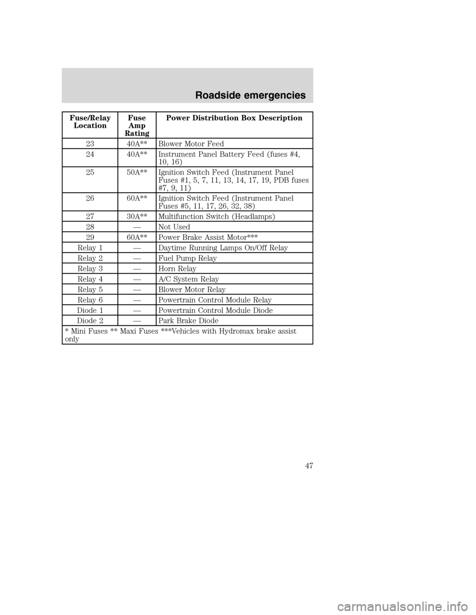
Fuse/Relay
LocationFuse
Amp
RatingPower Distribution Box Description
23 40A** Blower Motor Feed
24 40A** Instrument Panel Battery Feed (fuses #4,
10, 16)
25 50A** Ignition Switch Feed (Instrument Panel
Fuses #1, 5, 7, 11, 13, 14, 17, 19, PDB fuses
#7, 9, 11)
26 60A** Ignition Switch Feed (Instrument Panel
Fuses #5, 11, 17, 26, 32, 38)
27 30A** Multifunction Switch (Headlamps)
28 — Not Used
29 60A** Power Brake Assist Motor***
Relay 1 — Daytime Running Lamps On/Off Relay
Relay 2 — Fuel Pump Relay
Relay 3 — Horn Relay
Relay 4 — A/C System Relay
Relay 5 — Blower Motor Relay
Relay 6 — Powertrain Control Module Relay
Diode 1 — Powertrain Control Module Diode
Diode 2 — Park Brake Diode
* Mini Fuses ** Maxi Fuses ***Vehicles with Hydromax brake assist
only
Roadside emergencies
47
Page 54 of 104
4. Make the final connection of the negative (-) cable to an exposed
metal part of the stalled vehicle’s engine, away from the battery and the
carburetor/fuel injection system.Do notuse fuel lines, engine rocker
covers or the intake manifold asgroundingpoints.
Do not connect the end of the second cable to the negative (-)
terminal of the battery to be jumped. A spark may cause an
explosion of the gases that surround the battery.
5. Ensure that the cables are clear of fan blades, belts, moving parts of
both engines, or any fuel delivery system parts.
Jump starting
1. Start the engine of the booster vehicle and run the engine at
moderately increased speed.
2. Start the engine of the disabled vehicle.
3. Once the disabled vehicle has been started, run both engines for an
additional three minutes before disconnecting the jumper cables.
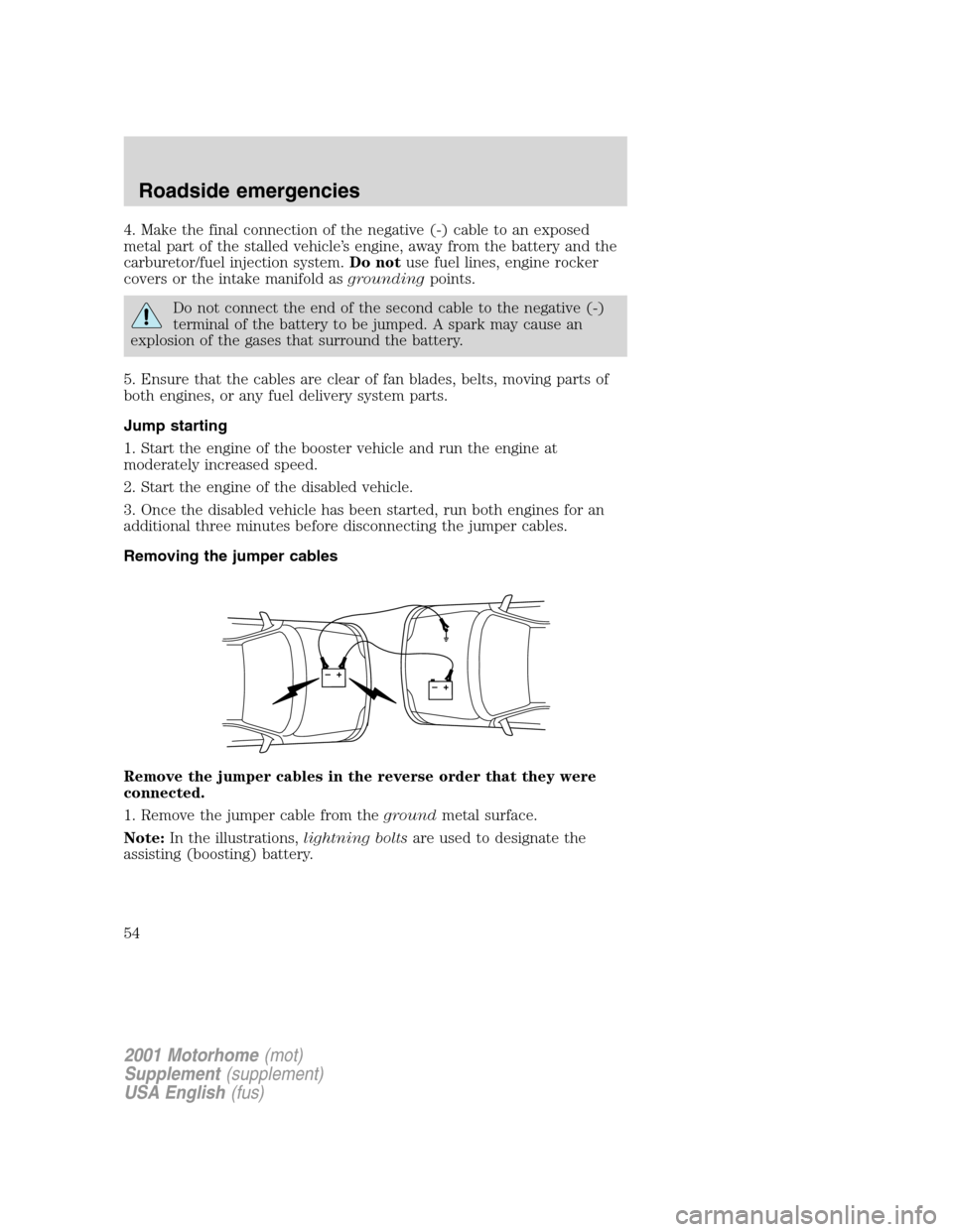
Removing the jumper cables
Remove the jumper cables in the reverse order that they were
connected.
1. Remove the jumper cable from thegroundmetal surface.
Note:In the illustrations,lightning boltsare used to designate the
assisting (boosting) battery.
+–+–
2001 Motorhome(mot)
Supplement(supplement)
USA English(fus)
Roadside emergencies
54