AUX FORD F650 2015 13.G Owners Manual
[x] Cancel search | Manufacturer: FORD, Model Year: 2015, Model line: F650, Model: FORD F650 2015 13.GPages: 384, PDF Size: 4.95 MB
Page 1 of 384
2015 F-650/750 Owner’s Manual
ford.cafordowner.com
December 2013
First Printing
Owner’s Manual
F-650/F-750
Litho in U.S.A.
FC4J 19A321 BA
Manuel du propriétaire F-650/750 2015
Décembre 2013
Première impression
Manuel du propriétaire
F-650/F-750
Imprimé aux États-Unis
FC4J 19A321 BA
Page 3 of 384
Windows and Mirrors 58
Power windows.......................................58
Exteriormirrors.......................................59
Instrument Cluster 63
Gauges.............................................63
Warning lamps and indicators.............................67
Audible warnings and indicators...........................72
Information Displays 73
Message center.......................................73
Information messages...................................75
Climate Control 76
Manual heating and air conditioning........................76
Seats 79
Sitting in the correct position.............................79
Head restraints........................................80
Manual seats.........................................83
Power seats..........................................85
Rear seats...........................................87
Heated seats.........................................89
Auxiliary Power Points 91
Starting and Stopping the Engine 92
Ignition switch........................................93
Engine block heater...................................100
Fuel and Refueling 103
Fuel quality.........................................104
Running out of fuel....................................106
Refueling...........................................107
Fuel consumption.....................................109
Diesel Exhaust Fluid (DEF).............................110
2Table of Contents
2015 F-650/750(f67)
Owners Guide gf(ownloose), 1st Printing, December 2013
Canadian_French(fr_can)
Page 6 of 384
Vehicle Care 234
Cleaning products.....................................234
Cleaning the exterior..................................234
Waxing.............................................236
Repairing minor paint damage............................236
Cleaning the engine...................................237
Cleaning the windows and wiper blades.....................237
Cleaning the interior...................................238
Cleaning the instrument panel and instrument cluster lens.......238
Cleaning leather seats..................................239
Cleaning the alloy wheels...............................239
Vehiclestorage.......................................240
Wheels and Tires 243
Tire information......................................243
Wheel lug nut torque..................................253
Capacities and Specifications 254
Engine drivebelt......................................254
Lubricant specifications.................................255
Refill capacities......................................268
Part numbers........................................272
Vehicle identification number............................272
Vehicle certification label...............................273
Audio System 275
AM/FMstereo........................................277
AM/FM/CD with SYNC.................................278
Auxiliary input jack...................................280
USBport...........................................282
Satellite radio information...............................282
Table of Contents5
2015 F-650/750(f67)
Owners Guide gf(ownloose), 1st Printing, December 2013
Canadian_French(fr_can)
Page 61 of 384
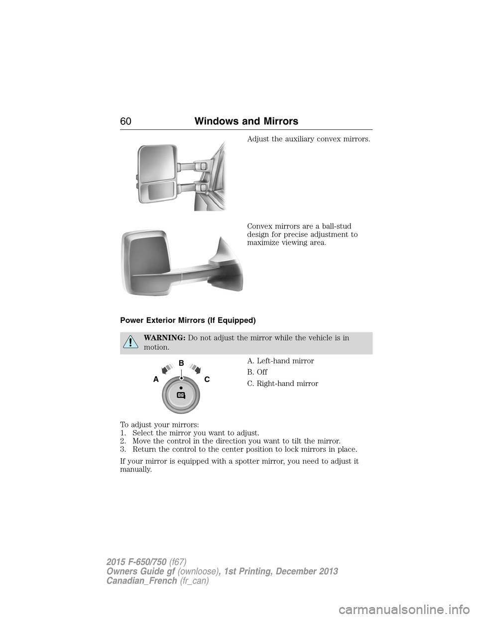
Adjust the auxiliary convex mirrors.
Convex mirrors are a ball-stud
design for precise adjustment to
maximize viewing area.
Power Exterior Mirrors (If Equipped)
WARNING:Do not adjust the mirror while the vehicle is in
motion.
A. Left-hand mirror
B. Off
C. Right-hand mirror
To adjust your mirrors:
1. Select the mirror you want to adjust.
2. Move the control in the direction you want to tilt the mirror.
3. Return the control to the center position to lock mirrors in place.
If your mirror is equipped with a spotter mirror, you need to adjust it
manually.
B
AC
60Windows and Mirrors
2015 F-650/750(f67)
Owners Guide gf(ownloose), 1st Printing, December 2013
Canadian_French(fr_can)
Page 92 of 384
AUXILIARY POWER POINTS
WARNING:Do not plug optional electrical accessories into the
cigarette lighter socket (if equipped). Improper use of the lighter
can cause damage not covered by your warranty, and can result in fire
or serious injury.
Note:If you use the power points when the engine is not running, the
battery may discharge and there may not be sufficient battery power to
start your engine.
Note:Do not insert objects other than an accessory plug into the power
point. This damages the outlet and blows the fuse.
Note:Do not hang any type of accessory or accessory bracket from the
plug.
Note:Do not use the power point over the vehicle capacity of 12–volt
DC 180 watts or a fuse may blow.
Note:Do not use the power point for operating a cigarette lighter
element.
Note:Improper use of the power point can cause damage not covered
by your warranty.
Note:Always keep the power point caps closed when they are not in
use.
Run the engine for full capacity use of the power point. To prevent the
battery from discharging:
•Do not use the power point longer than necessary when the engine is
not running.
•Do not leave devices plugged in overnight or when you park your
vehicle for extended periods.
Locations
Power points may be:
•On the instrument panel (two locations).
•Inside the center console storage compartment (if equipped).
•On the rear of the center console (if equipped).
•Inside the 20-percent front seat console (if equipped).
•Inside the rear under seat storage compartment (if equipped).
Auxiliary Power Points91
2015 F-650/750(f67)
Owners Guide gf(ownloose), 1st Printing, December 2013
Canadian_French(fr_can)
Page 127 of 384
Spicer ES56-7B and ES066-7B 7-speed
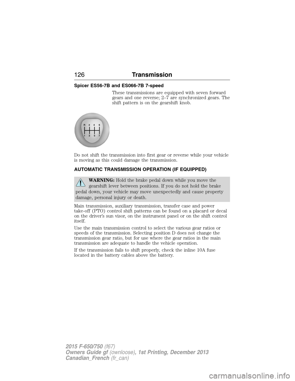
These transmissions are equipped with seven forward
gears and one reverse; 2–7 are synchronized gears. The
shift pattern is on the gearshift knob.
Do not shift the transmission into first gear or reverse while your vehicle
is moving as this could damage the transmission.
AUTOMATIC TRANSMISSION OPERATION (IF EQUIPPED)
WARNING:Hold the brake pedal down while you move the
gearshift lever between positions. If you do not hold the brake
pedal down, your vehicle may move unexpectedly and cause property
damage, personal injury or death.
Main transmission, auxiliary transmission, transfer case and power
take-off (PTO) control shift patterns can be found on a placard or decal
on the driver’s sun visor, on the instrument panel or on the shift control
itself.
Use the main transmission control to select the various gear ratios or
speeds of the transmission. Selecting position D does not change the
transmission gear ratio, but for use where the gear ratios in the main
transmission are adequate to handle the vehicle operation.
If the transmission fails to shift properly, check the inline 10A fuse
located in the battery cables above the battery.
R24
576
3 1
126Transmission
2015 F-650/750(f67)
Owners Guide gf(ownloose), 1st Printing, December 2013
Canadian_French(fr_can)
Page 133 of 384
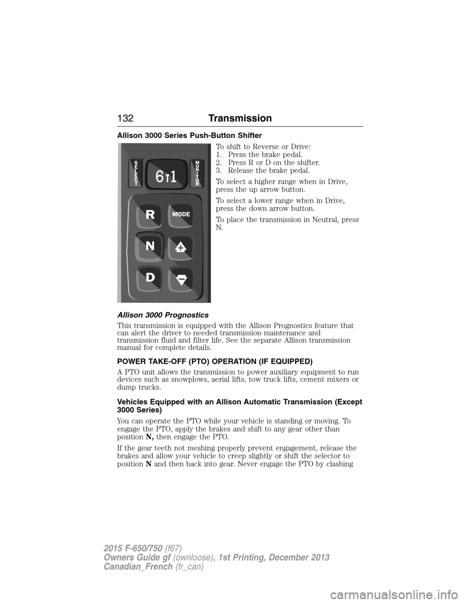
Allison 3000 Series Push-Button Shifter
To shift to Reverse or Drive:
1. Press the brake pedal.
2. Press R or D on the shifter.
3. Release the brake pedal.
To select a higher range when in Drive,
press the up arrow button.
To select a lower range when in Drive,
press the down arrow button.
To place the transmission in Neutral, press
N.
Allison 3000 Prognostics
This transmission is equipped with the Allison Prognostics feature that
can alert the driver to needed transmission maintenance and
transmission fluid and filter life. See the separate Allison transmission
manual for complete details.
POWER TAKE-OFF (PTO) OPERATION (IF EQUIPPED)
A PTO unit allows the transmission to power auxiliary equipment to run
devices such as snowplows, aerial lifts, tow truck lifts, cement mixers or
dump trucks.
Vehicles Equipped with an Allison Automatic Transmission (Except
3000 Series)
You can operate the PTO while your vehicle is standing or moving. To
engage the PTO, apply the brakes and shift to any gear other than
positionN,then engage the PTO.
If the gear teeth not meshing properly prevent engagement, release the
brakes and allow your vehicle to creep slightly or shift the selector to
positionNand then back into gear. Never engage the PTO by clashing
132Transmission
2015 F-650/750(f67)
Owners Guide gf(ownloose), 1st Printing, December 2013
Canadian_French(fr_can)
Page 143 of 384
HINTS ON DRIVING WITH ANTI-LOCK BRAKES
When the system is operating, the brake pedal pulses and may travel
further. Maintain pressure on the brake pedal. You may also hear a noise
from the system. This is normal.
The ABS does not eliminate the dangers inherent when:
•You drive too closely to the vehicle in front of you.
•Your vehicle is hydroplaning.
•You take corners too fast.
•The road surface is poor.
EXHAUST BRAKE (IF EQUIPPED)
WARNING:The exhaust brake is not recommended for use on
slippery or low traction road surfaces. Under these conditions a
loss of vehicle control could occur.
Note:Installing an exhaust or auxiliary brake does not necessarily
protect the engine from exceeding maximum governed speed. Use the
primary brakes to make sure the engine never exceeds maximum
governed speed under any conditions.
Note:Before starting the engine, make sure that the exhaust brake
switch is in the off position. Do not turn the exhaust brake on until the
engine has reached normal operating temperature.
Note:Maximum exhaust brake performance relates to the type of
transmission your vehicle has.
Note:Engine speed has a major influence of retarding performance.
When engine speed is stays at the maximum allowable level, the exhaust
brake operates at peak performance.
Note:Manual transmissions should be downshifted to the lowest gear
possible, without exceeding the maximum RPM limit of the engine. This
maximizes the exhaust brake’s retarding effect.
Note:Exhaust brakes operate effectively with automatic transmissions,
but performance varies with engine speed and the gear selected by the
transmission.
An exhaust brake is an auxiliary braking system that assists, but does
not replace, the primary service brake system. It helps control vehicle
speed; it is not a vehicle-stopping device.
142Brakes
2015 F-650/750(f67)
Owners Guide gf(ownloose), 1st Printing, December 2013
Canadian_French(fr_can)
Page 165 of 384
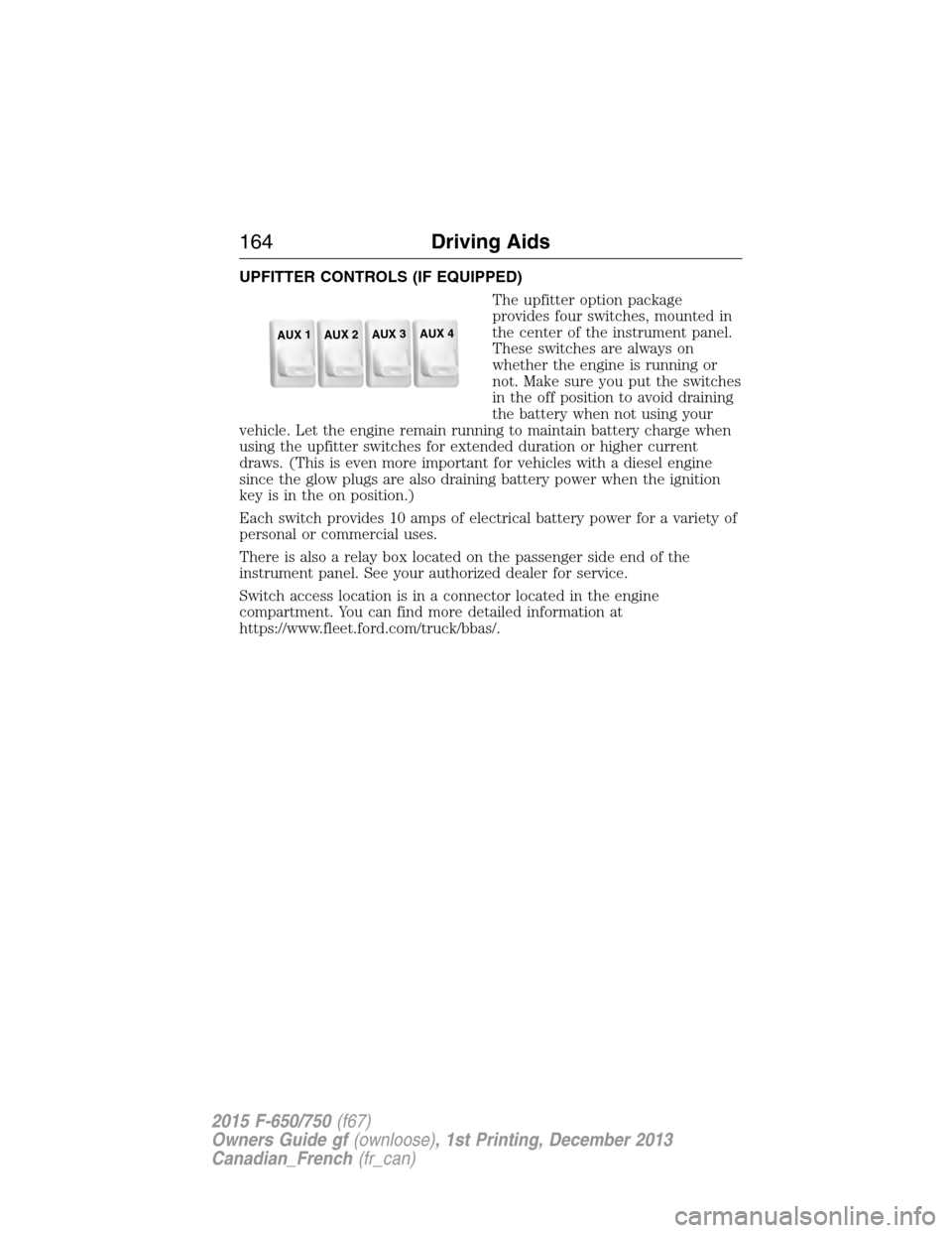
UPFITTER CONTROLS (IF EQUIPPED)
The upfitter option package
provides four switches, mounted in
the center of the instrument panel.
These switches are always on
whether the engine is running or
not. Make sure you put the switches
in the off position to avoid draining
the battery when not using your
vehicle. Let the engine remain running to maintain battery charge when
using the upfitter switches for extended duration or higher current
draws. (This is even more important for vehicles with a diesel engine
since the glow plugs are also draining battery power when the ignition
key is in the on position.)
Each switch provides 10 amps of electrical battery power for a variety of
personal or commercial uses.
There is also a relay box located on the passenger side end of the
instrument panel. See your authorized dealer for service.
Switch access location is in a connector located in the engine
compartment. You can find more detailed information at
https://www.fleet.ford.com/truck/bbas/.
AUX 1
AUX 2
AUX 3
AUX 4
164Driving Aids
2015 F-650/750(f67)
Owners Guide gf(ownloose), 1st Printing, December 2013
Canadian_French(fr_can)
Page 189 of 384
FUSE SPECIFICATION CHART
Power Distribution Box
WARNING:Always disconnect the battery before servicing high
current fuses.
WARNING:To reduce risk of electrical shock, always replace the
cover to the power distribution box before reconnecting the
battery or refilling fluid reservoirs.
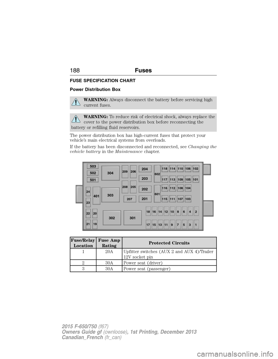
The power distribution box has high-current fuses that protect your
vehicle’s main electrical systems from overloads.
If the battery has been disconnected and reconnected, seeChanging the
vehicle batteryin theMaintenancechapter.
Fuse/Relay
LocationFuse Amp
RatingProtected Circuits
1 20A Upfitter switches (AUX 2 and AUX 4)/Trailer
12V socket pin
2 30A Power seat (driver)
3 30A Power seat (passenger)
503
502
304204
602118 114 110 106 102
117 113 109 105
116 112 108 104
115 111 107 103101
601 209
208206
205
207
203
202
201 303 501
401
302 301
18161412108642
1715131197531
24
23
22 20
21 19
188Fuses
2015 F-650/750(f67)
Owners Guide gf(ownloose), 1st Printing, December 2013
Canadian_French(fr_can)