light FORD F750 2002 10.G Service Manual
[x] Cancel search | Manufacturer: FORD, Model Year: 2002, Model line: F750, Model: FORD F750 2002 10.GPages: 256, PDF Size: 1.75 MB
Page 134 of 256
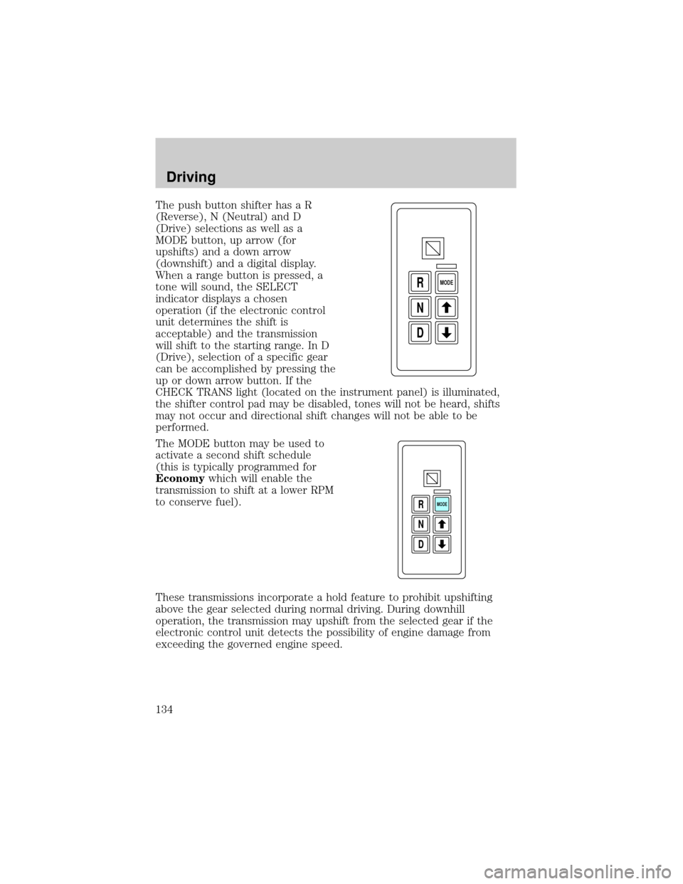
The push button shifter has a R
(Reverse), N (Neutral) and D
(Drive) selections as well as a
MODE button, up arrow (for
upshifts) and a down arrow
(downshift) and a digital display.
When a range button is pressed, a
tone will sound, the SELECT
indicator displays a chosen
operation (if the electronic control
unit determines the shift is
acceptable) and the transmission
will shift to the starting range. In D
(Drive), selection of a specific gear
can be accomplished by pressing the
up or down arrow button. If the
CHECK TRANS light (located on the instrument panel) is illuminated,
the shifter control pad may be disabled, tones will not be heard, shifts
may not occur and directional shift changes will not be able to be
performed.
The MODE button may be used to
activate a second shift schedule
(this is typically programmed for
Economywhich will enable the
transmission to shift at a lower RPM
to conserve fuel).
These transmissions incorporate a hold feature to prohibit upshifting
above the gear selected during normal driving. During downhill
operation, the transmission may upshift from the selected gear if the
electronic control unit detects the possibility of engine damage from
exceeding the governed engine speed.
D N R
MODE
D N R
MODE
Driving
134
Page 139 of 256
engine should be at idle speed when any shift from N (Neutral) to a
drive range is made.
The N (Neutral) position may also be used during stationary operation of
the Power Take-Off (PTO), if equipped.
Do not allow your vehicle to coast in N (Neutral). Engine
braking is not available in N (Neutral). Allowing your vehicle to
coast in N (Neutral) may result in loss of vehicle control and severe
internal transmission damage.
D (DriveÐNormal driving position)
In this position, the transmission starts in first gear and automatically
shifts through second, third, fourth and fifth depending on load and
speed demands. When the vehicle is slowing down, the transmission will
automatically downshift. This range is used for highway driving under
normal conditions.
4 and 2 (Fourth and Second)
Use this position when road, load or traffic conditions make it desirable
to restrict the automatic shifting to a lower range. These ranges provide
greater engine braking than D (Drive). When conditions no longer
require these lower gears, shift back to D (Drive).
1 (First)
The transmission has to be manually shifted into 1 (First) and will not
shift into a higher gear. Use this position when pulling through mud or
snow, driving up steep grades, hauling extra heavy loads or where
maximum reduction is required.
Power take-off (PTO) operation with an Allison automatic
transmission (except MD applications and vehicles equipped with
a Caterpillar 3126E engine)
The power take-off can be operated while the vehicle is standing or
moving.
To engage the PTO, apply the brakes and shift to any gear other than N
(Neutral) - this stops the rotation of the PTO drive gear in the
transmission - then engage the PTO.
If engagement is prevented by the gear teeth not meshing properly,
release the brakes and allow the vehicle to creep slightly - or shift the
selector to N (Neutral) and then back in gear. The PTO should never be
Driving
139
Page 141 of 256
Power take-off (PTO) operation on vehicles equipped with a
Caterpillar 3126E engine
If your vehicle is equipped with a Caterpillar 3126E engine, the PTO will
only operate if the vehicle is in Neutral. This feature can be overriden by
a special service tool; see your dealer or service representative for more
information.
DRIVING WITH A MANUAL TRANSMISSION (IF EQUIPPED)
Continued use of a damaged or worn clutch, prolonged clutch
slippage or downshifting at excessive speeds can result in a
failure of the engine, transmission or clutch components.
To avoid premature clutch wear and failure, do not drive with
your foot resting on the clutch pedal or use it to hold the vehicle
at a standstill on an upgrade as when waiting for a traffic light.
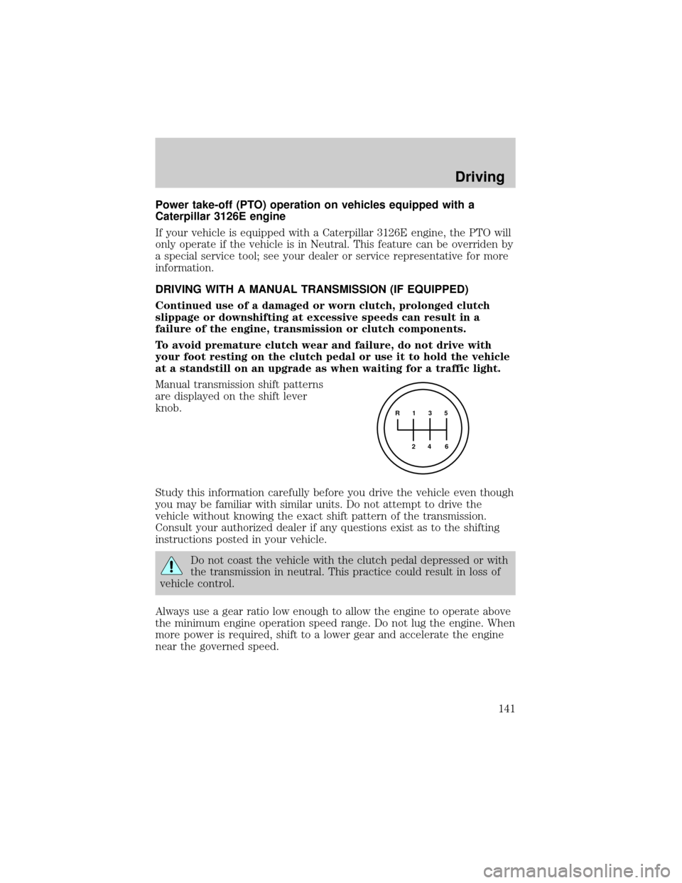
Manual transmission shift patterns
are displayed on the shift lever
knob.
Study this information carefully before you drive the vehicle even though
you may be familiar with similar units. Do not attempt to drive the
vehicle without knowing the exact shift pattern of the transmission.
Consult your authorized dealer if any questions exist as to the shifting
instructions posted in your vehicle.
Do not coast the vehicle with the clutch pedal depressed or with
the transmission in neutral. This practice could result in loss of
vehicle control.
Always use a gear ratio low enough to allow the engine to operate above
the minimum engine operation speed range. Do not lug the engine. When
more power is required, shift to a lower gear and accelerate the engine
near the governed speed.
R 1 3 5
4
6 2
Driving
141
Page 143 of 256
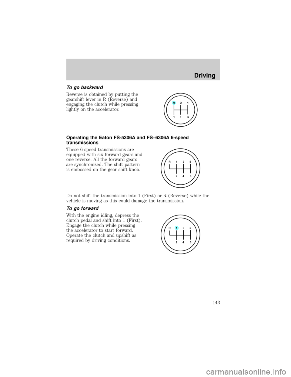
To go backward
Reverse is obtained by putting the
gearshift lever in R (Reverse) and
engaging the clutch while pressing
lightly on the accelerator.
Operating the Eaton FS-5306A and FS±6306A 6-speed
transmissions
These 6-speed transmissions are
equipped with six forward gears and
one reverse. All the forward gears
are synchronized. The shift pattern
is embossed on the gear shift knob.
Do not shift the transmission into 1 (First) or R (Reverse) while the
vehicle is moving as this could damage the transmission.
To go forward
With the engine idling, depress the
clutch pedal and shift into 1 (First).
Engage the clutch while pressing
the accelerator to start forward.
Operate the clutch and upshift as
required by driving conditions.
R 2 4
3 5 1
R 1 3 5
4
6 2
R 1 3 5
4
6 2
Driving
143
Page 144 of 256
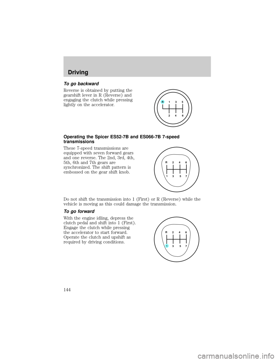
To go backward
Reverse is obtained by putting the
gearshift lever in R (Reverse) and
engaging the clutch while pressing
lightly on the accelerator.
Operating the Spicer ES52-7B and ES066-7B 7-speed
transmissions
These 7-speed transmissions are
equipped with seven forward gears
and one reverse. The 2nd, 3rd, 4th,
5th, 6th and 7th gears are
synchronized. The shift pattern is
embossed on the gear shift knob.
Do not shift the transmission into 1 (First) or R (Reverse) while the
vehicle is moving as this could damage the transmission.
To go forward
With the engine idling, depress the
clutch pedal and shift into 1 (First).
Engage the clutch while pressing
the accelerator to start forward.
Operate the clutch and upshift as
required by driving conditions.
R 1 3 5
4
6 2
2 4 6
3 5 71 R
2 4 6
3 5 7
1 R
Driving
144
Page 145 of 256
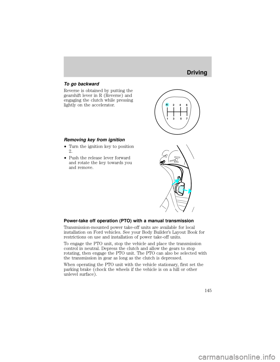
To go backward
Reverse is obtained by putting the
gearshift lever in R (Reverse) and
engaging the clutch while pressing
lightly on the accelerator.
Removing key from ignition
²Turn the ignition key to position
2.
²Push the release lever forward
and rotate the key towards you
and remove.
Power-take off operation (PTO) with a manual transmission
Transmission-mounted power take-off units are available for local
installation on Ford vehicles. See your Body Builder's Layout Book for
restrictions on use and installation of power take-off units.
To engage the PTO unit, stop the vehicle and place the transmission
control in neutral. Depress the clutch and allow the gears to stop
rotating, then engage the PTO unit. The PTO can also be selected with
the transmission in gear as long as the clutch is depressed.
When operating the PTO unit with the vehicle stationary, first set the
parking brake (chock the wheels if the vehicle is on a hill or other
unlevel surface).
2 4 6
3 5 7
1 R
Driving
145
Page 149 of 256
hubs (for trucks) or the bottom of the wheel rims (for cars).
Once through the water, always try the brakes. Wet brakes do not stop
the vehicle as effectively as dry brakes. Drying can be improved by
moving your vehicle slowly while applying light pressure on the brake
pedal.
Driving through deep water where the transmission vent tube is
submerged may allow water into the transmission and cause
internal transmission damage.
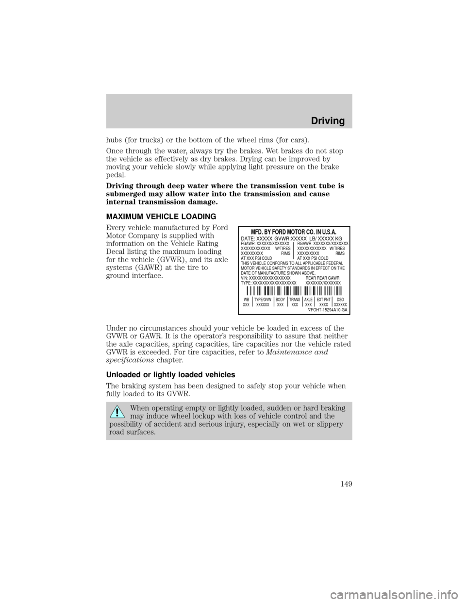
MAXIMUM VEHICLE LOADING
Every vehicle manufactured by Ford
Motor Company is supplied with
information on the Vehicle Rating
Decal listing the maximum loading
for the vehicle (GVWR), and its axle
systems (GAWR) at the tire to
ground interface.
Under no circumstances should your vehicle be loaded in excess of the
GVWR or GAWR. It is the operator's responsibility to assure that neither
the axle capacities, spring capacities, tire capacities nor the vehicle rated
GVWR is exceeded. For tire capacities, refer toMaintenance and
specificationschapter.
Unloaded or lightly loaded vehicles
The braking system has been designed to safely stop your vehicle when
fully loaded to its GVWR.
When operating empty or lightly loaded, sudden or hard braking
may induce wheel lockup with loss of vehicle control and the
possibility of accident and serious injury, especially on wet or slippery
road surfaces.
MFD. BY FORD MOTOR CO. IN U.S.A.
WB TYPE/GVW BODY TRANS AXLE EXT PNT DSO
XXX XXXXXX XXX XXX XXX XXXX XXXXXX
ÑFOHT-15294A10-GA
DATE: XXXXX GVWR:XXXXX LB/ XXXXX KGFGAWR: XXXXXX/XXXXXXX RGAWR: XXXXXXX/XXXXXXX
XXXXXXXXXXXX W/TIRES XXXXXXXXXXXX W/TIRES
XXXXXXXXX RIMS XXXXXXXXX RIMS
AT XXX PSI COLD AT XXX PSI COLD
THIS VEHICLE CONFORMS TO ALL APPLICABLE FEDERAL
MOTOR VEHICLE SAFETY STANDARDS IN EFFECT ON THE
DATE OF MANUFACTURE SHOWN ABOVE.
VIN: XXXXXXXXXXXXXXXXX REAR REAR GAWR
TYPE: XXXXXXXXXXXXXXXXXX XXXXXXX/XXXXXXX
Driving
149
Page 151 of 256
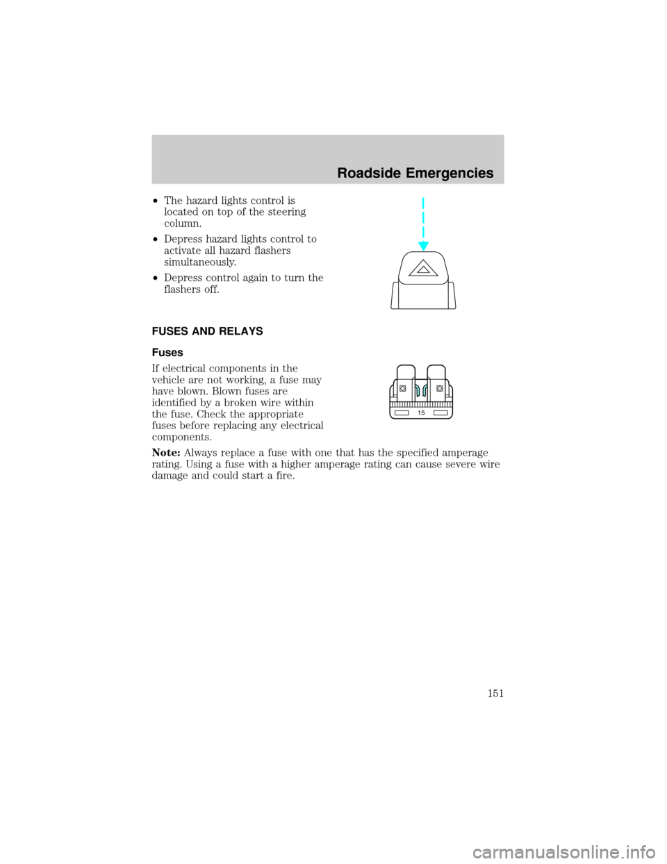
²The hazard lights control is
located on top of the steering
column.
²Depress hazard lights control to
activate all hazard flashers
simultaneously.
²Depress control again to turn the
flashers off.
FUSES AND RELAYS
Fuses
If electrical components in the
vehicle are not working, a fuse may
have blown. Blown fuses are
identified by a broken wire within
the fuse. Check the appropriate
fuses before replacing any electrical
components.
Note:Always replace a fuse with one that has the specified amperage
rating. Using a fuse with a higher amperage rating can cause severe wire
damage and could start a fire.
15
Roadside Emergencies
151
Page 153 of 256
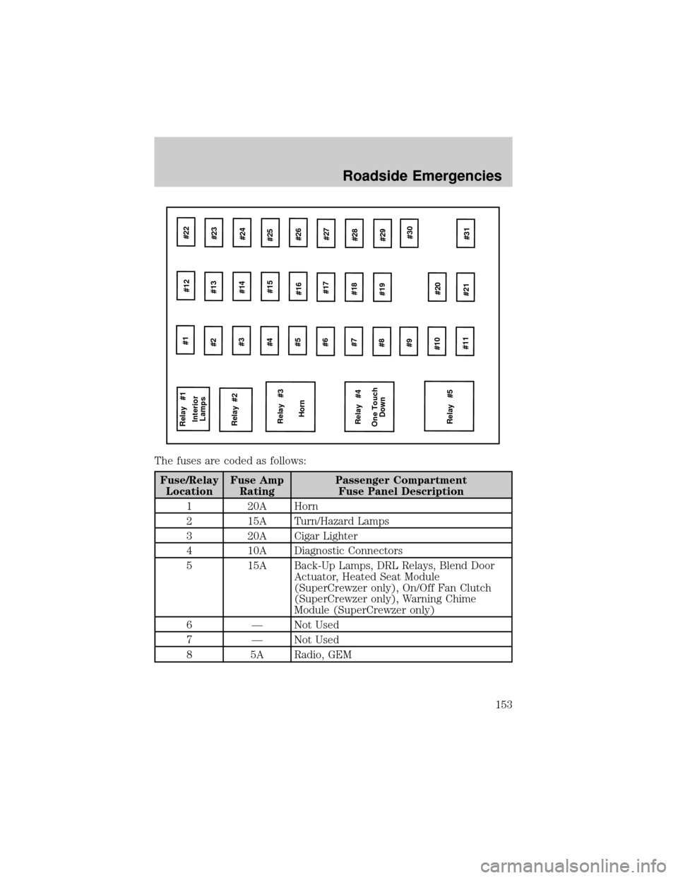
The fuses are coded as follows:
Fuse/Relay
LocationFuse Amp
RatingPassenger Compartment
Fuse Panel Description
1 20A Horn
2 15A Turn/Hazard Lamps
3 20A Cigar Lighter
4 10A Diagnostic Connectors
5 15A Back-Up Lamps, DRL Relays, Blend Door
Actuator, Heated Seat Module
(SuperCrewzer only), On/Off Fan Clutch
(SuperCrewzer only), Warning Chime
Module (SuperCrewzer only)
6 Ð Not Used
7 Ð Not Used
8 5A Radio, GEM
Relay #1
Relay #2
Relay #3
Horn
Relay #4
Relay #5 One Touch
Down Interior
Lamps#1
#12#22
#2
#3
#4
#5
#6
#7
#8
#9
#10
#11#13
#23
#14
#15
#16
#17#24
#25
#26
#27
#18
#28
#19
#29
#20
#21#30
#31
Roadside Emergencies
153
Page 162 of 256
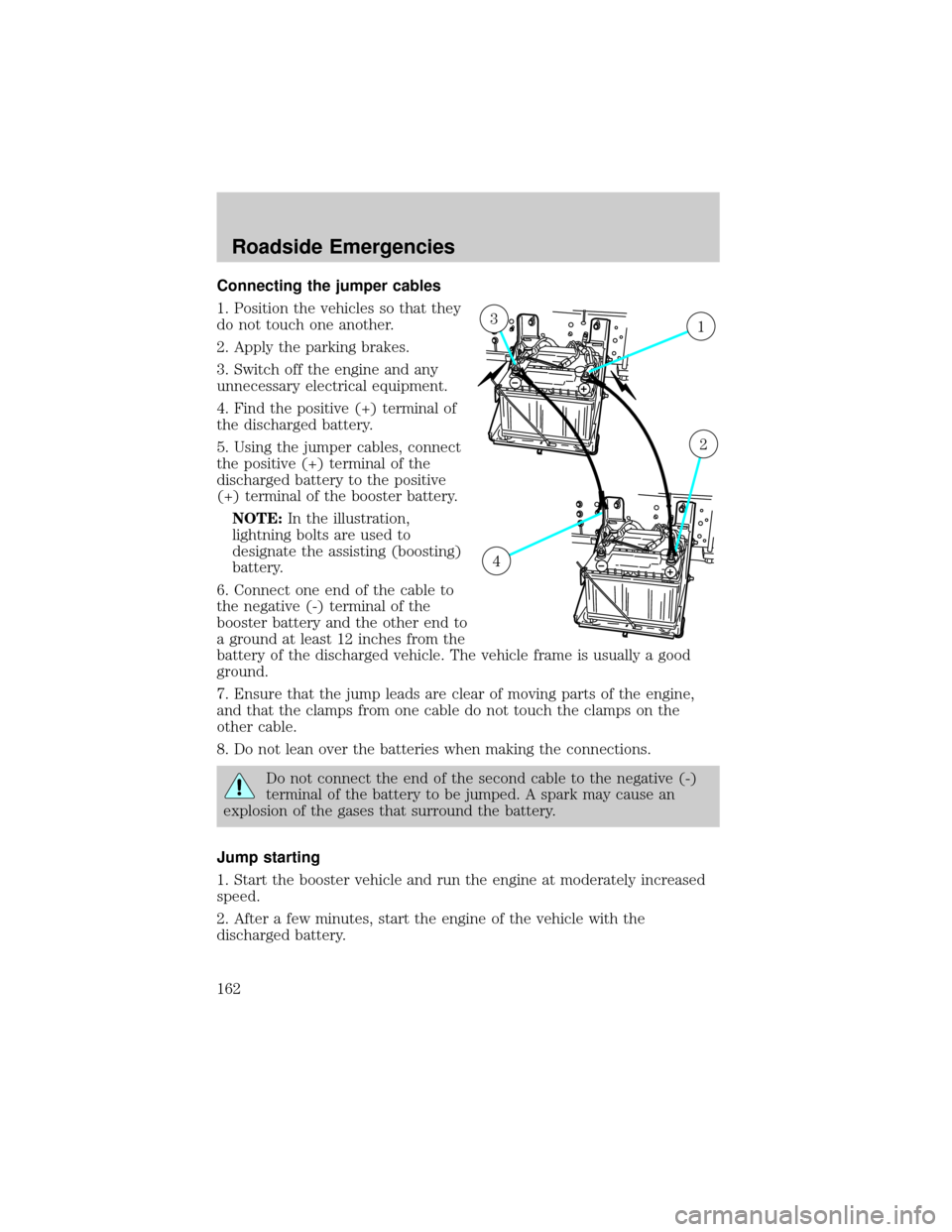
Connecting the jumper cables
1. Position the vehicles so that they
do not touch one another.
2. Apply the parking brakes.
3. Switch off the engine and any
unnecessary electrical equipment.
4. Find the positive (+) terminal of
the discharged battery.
5. Using the jumper cables, connect
the positive (+) terminal of the
discharged battery to the positive
(+) terminal of the booster battery.
NOTE:In the illustration,
lightning bolts are used to
designate the assisting (boosting)
battery.
6. Connect one end of the cable to
the negative (-) terminal of the
booster battery and the other end to
a ground at least 12 inches from the
battery of the discharged vehicle. The vehicle frame is usually a good
ground.
7. Ensure that the jump leads are clear of moving parts of the engine,
and that the clamps from one cable do not touch the clamps on the
other cable.
8. Do not lean over the batteries when making the connections.
Do not connect the end of the second cable to the negative (-)
terminal of the battery to be jumped. A spark may cause an
explosion of the gases that surround the battery.
Jump starting
1. Start the booster vehicle and run the engine at moderately increased
speed.
2. After a few minutes, start the engine of the vehicle with the
discharged battery.
13
2
4
Roadside Emergencies
162