key FORD FESTIVA 1991 User Guide
[x] Cancel search | Manufacturer: FORD, Model Year: 1991, Model line: FESTIVA, Model: FORD FESTIVA 1991Pages: 454, PDF Size: 9.53 MB
Page 168 of 454
Back To Article
G - T EST S W/CODES
1991-92 ENGINE PERFORMANCE Ford Motor Co. Self-Diagnostics
INTRODUCTION
If no faults were found while performing BASIC TESTING , proceed with self-diagnostics. If no fault codes or only pass codes are present
after entering self-diagnostics, proceed to TESTS W/O CODES article in the ENGINE PERFORMANCE Section for diagnosis by symptom
(i.e., ROUGH IDLE, NO START, etc.).
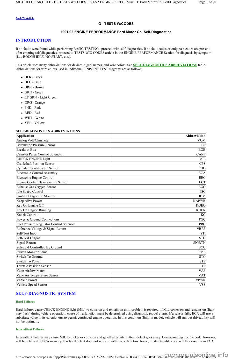
This article uses many abbreviations for devices, signal names, and wire colors. See SELF
-DIAGNOSTICS ABBREVIATIONS table.
Abbreviations for wire colors used in individual PINPOINT TEST diagrams are as follows:
BLK - Black
BLU - Blue
BRN - Brown
GRN - Green
LT GRN - Light Green
ORG - Orange
PNK - Pink
RED - Red
WHT - White
YEL - Yellow
SELF-DIAGNOSTICS ABBREVIATIONS
SELF-DIAGNOSTIC SYSTEM
Hard Failures
Hard failures cause CHECK ENGINE light (MIL) to come on and remain on until problem is repaired. If MIL comes on and remains on (light
may flash) during vehicle operation, cause of malfunction must be determined using diagnostic (code) charts. If a sensor fails, ECA will use a
substitute value in its calculations to permit continued engine operation. In this condition (limp-in mode), vehicle will run but driveability will
not be optimum.
Intermittent Failures
Intermittent failures may cause MIL to flicker or come on and go off after intermittent defect goes away. Corresponding trouble code, however,
will be retained in ECA memory. If related defect does not reoccur within a certain time frame, related trouble code will be erased from ECA
ApplicationAbbreviation
Analog Volt/OhmmeterVOM
Barometric Pressure SensorBP
Breakout BoxBOB
Canister Purge Control SolenoidCANP
CHECK ENGINE LightMIL
Crankshaft Position SensorCPS
Cylinder Identification SensorCID
Electronic Control AssemblyECA
Electronic Engine ControlEEC
Engine Coolant Temperature SensorECT
Exhaust Gas Oxygen SensorEGO
Idle Speed ControlISC
Ignition Diagnostic MonitorIDM
Keep Alive PowerKAPWR
Key On Engine OffKOEO
Key On Engine RunningKOER
Knock ControlKC
Power & Ground ConnectionsPGC
Fuel Pressure Regulator Control SolenoidPRC
Reference Voltage & Signal ReturnVREF
Self-Test InputSTI
Self-Test OutputSTO
Signal ReturnSIGRTN
Solenoid Controlled By GroundSCG
Switch Monitor LampSML
Switch To GroundSTG
Switch To PowerSTP
Throttle Position SensorTP
Vane Airflow MeterVAF
Vane Air Temperature SensorVAT
Vehicle PowerVPWR
Vehicle Speed SensorVSS
Page 1 of 20 MITCHELL 1 ARTICLE - G - TESTS W/CODES 1991-92 ENGINE PERFORMANCE Ford Motor Co. Self-Diagnostics
3/10/2009 http://www.eautorepair.net/app/PrintItems.asp?S0=2097152&S1=0&SG=%7B7DD6473C%2DB5BB%2D4F20%2D9D70%2D
...
Page 171 of 454
CLEARING CODES
Clearing Codes Procedure
Disconnect negative battery cable. Press brake pedal for 5-10 seconds. Turn off VOM or Super Star II tester. Reconnect battery.
ECA LOCATION
ECA is located on center console behind kick panel on Capri, and under instrument panel on driver side of Festiva.
QUICK TESTS
KEY ON, ENGINE OFF (KOEO) SELF-TEST
KOEO
1. This is a test of electronic engine control system, conducted with power (voltage) applied and engine not running. Activate self-test, and
record all codes displayed.
2. Erase codes, and repeat self-test. Diagnose only codes occurring during repeat self-test. See TROUBLE CODE DEFINITION
table. If
no codes are present, proceed to KEY ON, ENGINE RUNNING (KOER) SELF
-TEST .
KEY ON, ENGINE RUNNING (KOER) SELF-TEST
KOER
1. Deactivate self-test. Start and run engine at 2000 RPM for 2 minutes to warm up EGO sensor. Turn off engine and wait 10 seconds.
2. Restart engine, and activate self-test. Record all service codes displayed. See TROUBLE CODE DEFINITION
table. If no codes are
present, proceed to SWITCH MONITOR TEST
.
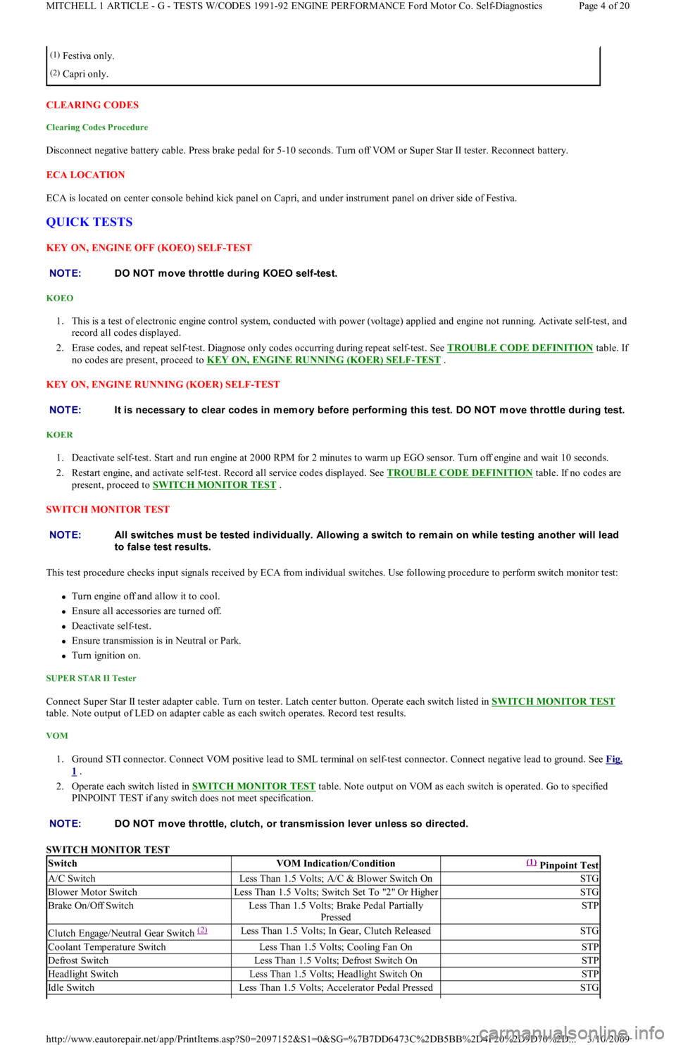
SWITCH MONITOR TEST
This test procedure checks input signals received by ECA from individual switches. Use following procedure to perform switch monitor test:
Turn engine off and allow it to cool.
Ensure all accessories are turned off.
Deactivate self-test.
Ensure transmission is in Neutral or Park.
Turn ignition on.
SUPER STAR II Tester
Connect Super Star II tester adapter cable. Turn on tester. Latch center button. Operate each switch listed in SWITCH MONITOR TEST
table. Note output of LED on adapter cable as each switch operates. Record test results.
VOM
1. Ground STI connector. Connect VOM positive lead to SML terminal on self-test connector. Connect negative lead to ground. See Fig.
1 .
2. Operate each switch listed in SWITCH MONITOR TEST
table. Note output on VOM as each switch is operated. Go to specified
PINPOINT TEST if any switch does not meet specification.
SWITCH MONITOR TEST
(1)Festiva only.
(2)Capri only.
NOTE:DO NOT m ove throttle during KOEO self-test.
NOTE:It is necessary to clear codes in m em ory before perform ing this test. DO NOT m ove throttle during test.
NOTE:All switches m ust be tested individually. Allowing a switch to rem ain on while testing another will lead
to false test results.
NOTE:DO NOT m ove throttle, clutch, or transm ission lever unless so directed.
SwitchVOM Indication/Condition(1) Pinpoint Test
A/C SwitchLess Than 1.5 Volts; A/C & Blower Switch OnSTG
Blower Motor SwitchLess Than 1.5 Volts; Switch Set To "2" Or HigherSTG
Brake On/Off SwitchLess Than 1.5 Volts; Brake Pedal Partially
PressedSTP
Clutch Engage/Neutral Gear Switch (2) Less Than 1.5 Volts; In Gear, Clutch ReleasedSTG
Coolant Temperature SwitchLess Than 1.5 Volts; Cooling Fan OnSTP
Defrost SwitchLess Than 1.5 Volts; Defrost Switch OnSTP
Headlight SwitchLess Than 1.5 Volts; Headlight Switch OnSTP
Id l e Swit chLess Than 1.5 Volts; Accelerator Pedal PressedSTG
Page 4 of 20 MITCHELL 1 ARTICLE - G - TESTS W/CODES 1991-92 ENGINE PERFORMANCE Ford Motor Co. Self-Diagnostics
3/10/2009 http://www.eautorepair.net/app/PrintItems.asp?S0=2097152&S1=0&SG=%7B7DD6473C%2DB5BB%2D4F20%2D9D70%2D
...
Page 172 of 454
WIGGLE TEST
Checking Circuitry
1. Visually inspect suspected sensor, switch, or solenoid. Enter WIGGLE TEST if using Super Star II tester. If using VOM, connect it to
STO terminal on self-test connector, and ground STI self-test connector terminal. Lightly tap sensor, switch, or solenoid.
2. Push and pull on suspected sensor, switch, or solenoid connector, but DO NOT unplug it. Test and wiggle harness vigorously, working
in small sections, from suspected device toward dash panel, and from dash panel to ECA.
3. If VOM or Super Star II tester does not display a positive indication of an intermittent defect, carefully disconnect suspected device.
Remove terminals from connector.
4. Inspect terminals at both ends for corrosion, bad crimps, or improperly seated terminals. Reconnect after inspection. Unplug harness
fro m E CA.
5. Inspect ECA and harness connector terminals for corrosion, bad crimps, or improperly seated terminals. If VOM does not indicate any
intermittent defect, reconnect wiring and erase codes.
PINPOINT TESTS
HOW TO USE PINPOINT TESTS
1. DO NOT perform any PINPOINT TEST unless directed by a QUICK TESTS procedure. Ensure all non-EEC related defects are
corrected. Follow each test step in order until defect is found. DO NOT replace any part unless so directed. When more than one service
code exists, start with first code displayed.
2. PINPOINT TESTS require ensuring electrical circuits are okay before replacing sensors or any other components. Always test circuits
for continuity between sensor and ECA. Test all circuits for shorts to power, opens, or shorts to ground. VREF and VPWR circuits
should be tested with KOEO or as specified in PINPOINT TESTS.
3. DO NOT measure voltage or resistance at ECA, or connect any test light unless specified in testing procedure. DO NOT pierce wiring.
Isolate both ends of a circuit and turn key off whenever checking for shorts or continuity, unless otherwise specified.
4. Disconnect solenoids and switches before checking circuit continuity or energizing solenoids.
5. An open is defined as any resistance greater than 10,000 ohms, unless otherwise specified.
6. To help diagnose circuits to ECA, turn ignition off and disconnect ECA harness. Connect BOB between ECA and ECA harness to
perform circuit and pinpoint tests.
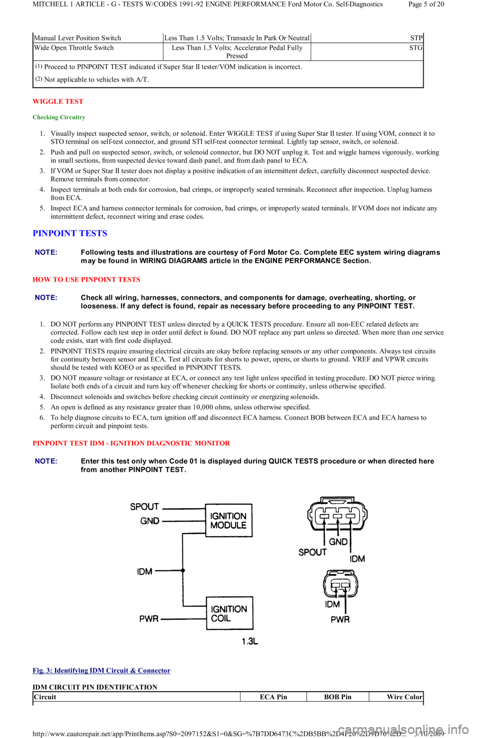
PINPOINT TEST IDM - IGNITION DIAGNOSTIC MONITOR
Fig. 3: Identifying IDM Circuit & Connector
IDM CIRCUIT PIN IDENTIFICATION
Manual Lever Position SwitchLess Than 1.5 Volts; Transaxle In Park Or NeutralSTP
Wide Open Throttle SwitchLess Than 1.5 Volts; Accelerator Pedal Fully
PressedSTG
(1)Proceed to PINPOINT TEST indicated if Super Star II tester/VOM indication is incorrect.
(2)Not applicable to vehicles with A/T.
NOTE:Following tests and illustrations are courtesy of Ford Motor Co. Com plete EEC system wiring diagram s
m ay be found in WIRING DIAGRAMS article in the ENGINE PERFORMANCE Section.
NOTE:Check all wiring, harnesses, connectors, and com ponents for dam age, overheating, shorting, or
looseness. If any defect is found, repair as necessary before proceeding to any PINPOINT T EST .
NOTE:Enter this test only when Code 01 is displayed during QUICK T EST S procedure or when directed here
from another PINPOINT TEST.
CircuitECA PinBOB PinWire Color
Page 5 of 20 MITCHELL 1 ARTICLE - G - TESTS W/CODES 1991-92 ENGINE PERFORMANCE Ford Motor Co. Self-Diagnostics
3/10/2009 http://www.eautorepair.net/app/PrintItems.asp?S0=2097152&S1=0&SG=%7B7DD6473C%2DB5BB%2D4F20%2D9D70%2D
...
Page 207 of 454
"J"
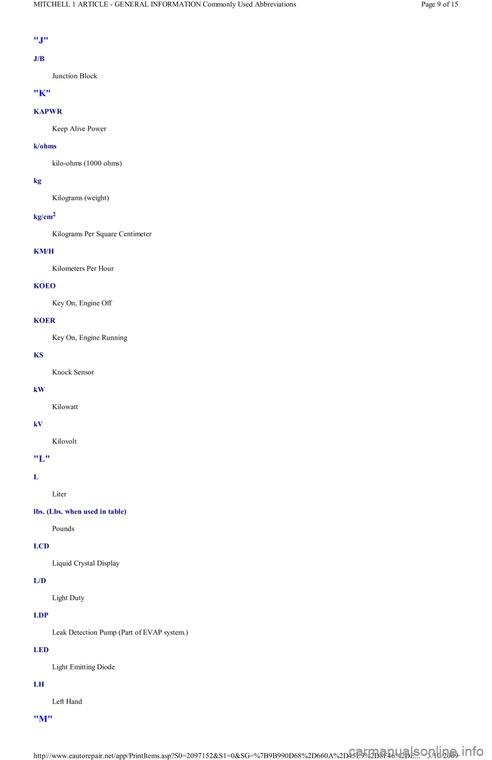
J/B
Junction Block
"K"
KAPWR
Keep Alive Power
k/ohms
kilo-ohms (1000 ohms)
kg
Kilograms (weight)
kg/cm
2
Kilograms Per Square Centimeter
KM/H
Kilometers Per Hour
KOEO
Key On, Engine Off
KOER
Ke y On , E n gin e R u n n in g
KS
Knock Sensor
kW
Kilowatt
kV
Kilovolt
"L"
L
Liter
lbs. (Lbs. when used in table)
Pounds
LCD
Liquid Crystal Display
L/D
Light Duty
LDP
Leak Detection Pump (Part of EVAP system.)
LED
Light Emitting Diode
LH
Left Hand
"M"
Page 9 of 15 MITCHELL 1 ARTICLE - GENERAL INFORMATION Commonly Used Abbreviations
3/10/2009 http://www.eautorepair.net/app/PrintItems.asp?S0=2097152&S1=0&SG=%7B9B990D68%2D660A%2D45E9%2D8F46%2DE
...
Page 219 of 454
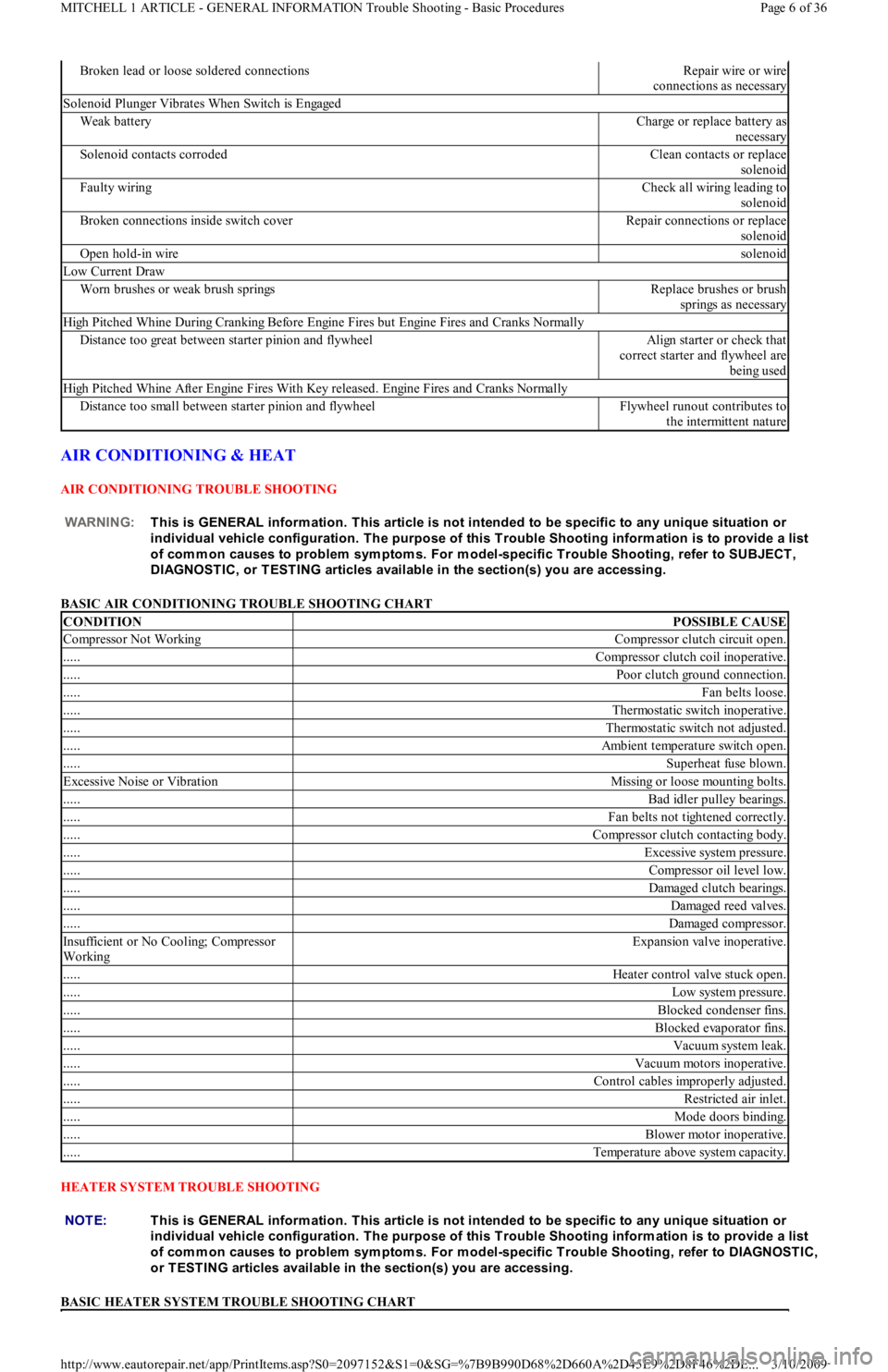
AIR CONDITIONING & HEAT
AIR CONDITIONING TROUBLE SHOOTING
BASIC AIR CONDITIONING TROUBLE SHOOTING CHART
HEATER SYSTEM TROUBLE SHOOTING
BASIC HEATER SYSTEM TROUBLE SHOOTING CHART
Broken lead or loose soldered connectionsRepair wire or wire
connections as necessary
Solenoid Plunger Vibrates When Switch is Engaged
Weak batteryCharge or replace battery as
necessary
Solenoid contacts corrodedClean contacts or replace
solenoid
Faulty wiringCheck all wiring leading to
solenoid
Broken connections inside switch coverRepair connections or replace
solenoid
Open hold-in wiresolenoid
Low Current Draw
Worn brushes or weak brush springsReplace brushes or brush
springs as necessary
High Pitched Whine During Cranking Before Engine Fires but Engine Fires and Cranks Normally
Distance too great between starter pinion and flywheelAlign starter or check that
correct starter and flywheel are
being used
High Pitched Whine After Engine Fires With Key released. Engine Fires and Cranks Normally
Distance too small between starter pinion and flywheelFlywheel runout contributes to
the intermittent nature
WARNING:This is GENERAL inform ation. This article is not intended to be specific to any unique situation or
individual vehicle configuration. T he purpose of this T rouble Shooting inform ation is to provide a list
of com m on causes to problem sym ptom s. For m odel-specific T rouble Shooting, refer to SUBJECT ,
DIAGNOST IC, or T EST ING articles available in the section(s) you are accessing.
CONDITIONPOSSIBLE CAUSE
Compressor Not WorkingCompressor clutch circuit open.
.....Compressor clutch coil inoperative.
.....Poor clutch ground connection.
.....Fan belts loose.
.....Thermostatic switch inoperative.
.....Thermostatic switch not adjusted.
.....Ambient temperature switch open.
.....Superheat fuse blown.
Excessive Noise or VibrationMissing or loose mounting bolts.
.....Bad idler pulley bearings.
.....Fan belts not tightened correctly.
.....Compressor clutch contacting body.
.....Excessive system pressure.
.....Compressor oil level low.
.....Damaged clutch bearings.
.....Damaged reed valves.
.....Damaged compressor.
In su fficien t o r No Co o l in g; Co mp resso r
WorkingExpansion valve inoperative.
.....Heater control valve stuck open.
.....Low system pressure.
.....Blocked condenser fins.
.....Blocked evaporator fins.
.....Vacuum system leak.
.....Vacuum motors inoperative.
.....Control cables improperly adjusted.
.....Restricted air inlet.
.....Mode doors binding.
.....Blower motor inoperative.
.....Temperature above system capacity.
NOTE:This is GENERAL inform ation. This article is not intended to be specific to any unique situation or
individual vehicle configuration. T he purpose of this T rouble Shooting inform ation is to provide a list
of com m on causes to problem sym ptom s. For m odel-specific T rouble Shooting, refer to DIAGNOST IC,
or T EST ING articles available in the section(s) you are accessing.
Page 6 of 36 MITCHELL 1 ARTICLE - GENERAL INFORMATION Trouble Shooting - Basic Procedures
3/10/2009 http://www.eautorepair.net/app/PrintItems.asp?S0=2097152&S1=0&SG=%7B9B990D68%2D660A%2D45E9%2D8F46%2DE
...
Page 234 of 454
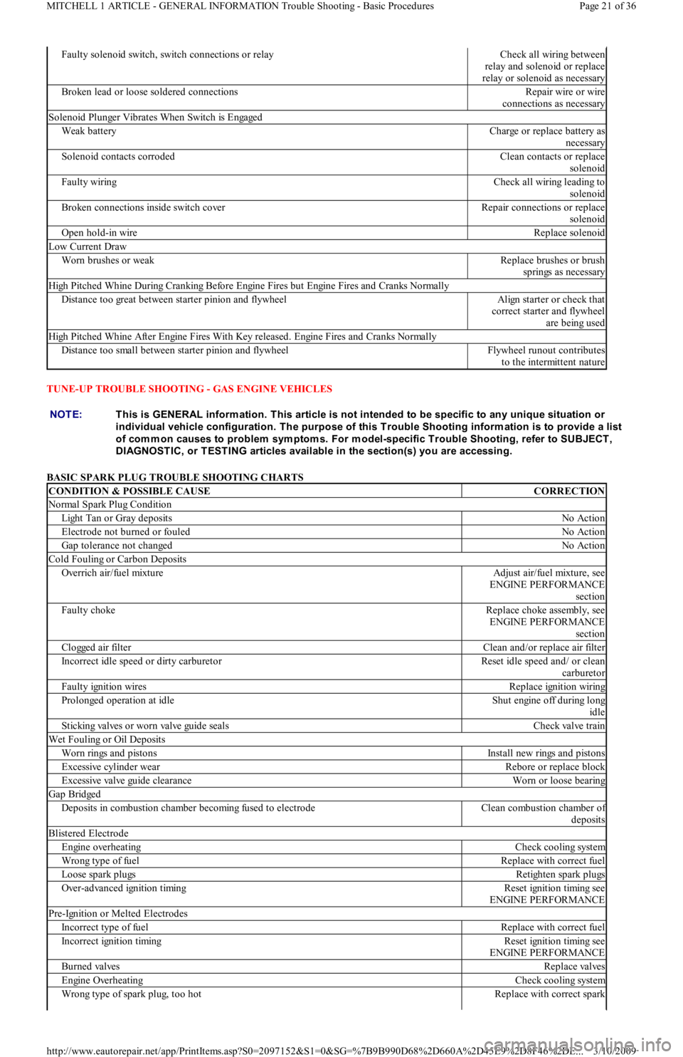
TUNE-UP TROUBLE SHOOTING - GAS ENGINE VEHICLES
BASIC SPARK PLUG TROUBLE SHOOTING CHARTS
Faulty solenoid switch, switch connections or relayCheck all wiring between
relay and solenoid or replace
relay or solenoid as necessary
Broken lead or loose soldered connectionsRepair wire or wire
connections as necessary
Solenoid Plunger Vibrates When Switch is Engaged
Weak batteryCharge or replace battery as
necessary
Solenoid contacts corrodedClean contacts or replace
solenoid
Faulty wiringCheck all wiring leading to
solenoid
Broken connections inside switch coverRepair connections or replace
solenoid
Open hold-in wireReplace solenoid
Low Current Draw
Worn brushes or weakReplace brushes or brush
springs as necessary
High Pitched Whine During Cranking Before Engine Fires but Engine Fires and Cranks Normally
Distance too great between starter pinion and flywheelAlign starter or check that
correct starter and flywheel
are being used
High Pitched Whine After Engine Fires With Key released. Engine Fires and Cranks Normally
Distance too small between starter pinion and flywheelFlywheel runout contributes
to the intermittent nature
NOTE:This is GENERAL inform ation. This article is not intended to be specific to any unique situation or
individual vehicle configuration. T he purpose of this T rouble Shooting inform ation is to provide a list
of com m on causes to problem sym ptom s. For m odel-specific T rouble Shooting, refer to SUBJECT ,
DIAGNOST IC, or T EST ING articles available in the section(s) you are accessing.
CONDITION & POSSIBLE CAUSECORRECTION
Normal Spark Plug Condition
Light Tan or Gray depositsNo Action
Electrode not burned or fouledNo Action
Gap tolerance not changedNo Action
Cold Fouling or Carbon Deposits
Overrich air/fuel mixtureAdjust air/fuel mixture, see
ENGINE PERFORMANCE
section
Faulty chokeReplace choke assembly, see
ENGINE PERFORMANCE
section
Clogged air filterClean and/or replace air filter
Incorrect idle speed or dirty carburetorReset idle speed and/ or clean
carburetor
Faulty ignition wiresReplace ignition wiring
Prolonged operation at idleShut engine off during long
idle
Sticking valves or worn valve guide sealsCheck valve train
Wet Fouling or Oil Deposits
Worn rings and pistonsInstall new rings and pistons
Excessive cylinder wearRebore or replace block
Excessive valve guide clearanceWorn or loose bearing
Gap Bridged
Deposits in combustion chamber becoming fused to electrodeClean combustion chamber of
deposits
Blistered Electrode
Engine overheatingCheck cooling system
Wrong type of fuelReplace with correct fuel
Loose spark plugsRetighten spark plugs
Over-advanced ignition timingReset ignition timing see
ENGINE PERFORMANCE
Pre-Ignition or Melted Electrodes
Incorrect type of fuelReplace with correct fuel
Incorrect ignition timingReset ignition timing see
ENGINE PERFORMANCE
Burned valvesReplace valves
Engine OverheatingCheck cooling system
Wrong type of spark plug, too hotReplace with correct spark
Page 21 of 36 MITCHELL 1 ARTICLE - GENERAL INFORMATION Trouble Shooting - Basic Procedures
3/10/2009 http://www.eautorepair.net/app/PrintItems.asp?S0=2097152&S1=0&SG=%7B9B990D68%2D660A%2D45E9%2D8F46%2DE
...
Page 252 of 454
Back To Article
GENERAL INFORMATION
Com puter Relearn Procedures
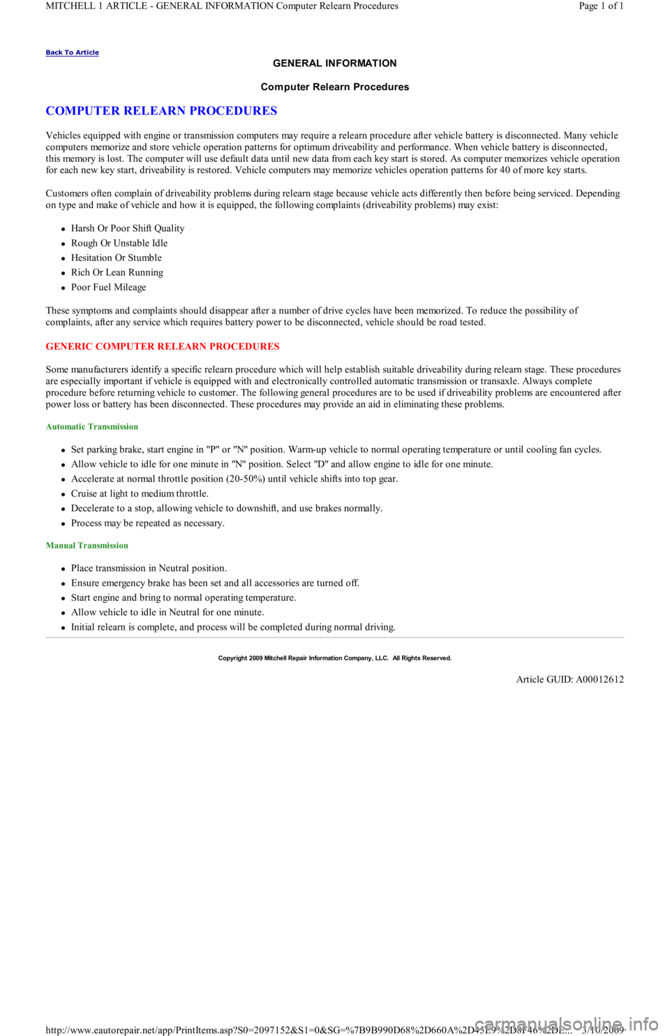
COMPUTER RELEARN PROCEDURES
Vehicles equipped with engine or transmission computers may require a relearn procedure after vehicle battery is disconnected. Many vehicle
computers memorize and store vehicle operation patterns for optimum driveability and performance. When vehicle battery is disconnected,
this memory is lost. The computer will use default data until new data from each key start is stored. As computer memorizes vehicle operation
for each new key start, driveability is restored. Vehicle computers may memorize vehicles operation patterns for 40 of more key starts.
Customers often complain of driveability problems during relearn stage because vehicle acts differently then before being serviced. Depending
on type and make of vehicle and how it is equipped, the following complaints (driveability problems) may exist:
Harsh Or Poor Shift Quality
Rough Or Unstable Idle
Hesitation Or Stumble
Rich Or Lean Running
Poor Fuel Mileage
These symptoms and complaints should disappear after a number of drive cycles have been memorized. To reduce the possibility of
complaints, after any service which requires battery power to be disconnected, vehicle should be road tested.
GENERIC COMPUTER RELEARN PROCEDURES
Some manufacturers identify a specific relearn procedure which will help establish suitable driveability during relearn stage. These procedures
are especially important if vehicle is equipped with and electronically controlled automatic transmission or transaxle. Always complete
procedure before returning vehicle to customer. The following general procedures are to be used if driveability problems are encountered after
power loss or battery has been disconnected. These procedures may provide an aid in eliminating these problems.
Automatic Transmission
Set parking brake, start engine in "P" or "N" position. Warm-up vehicle to normal operating temperature or until cooling fan cycles.
Allow vehicle to idle for one minute in "N" position. Select "D" and allow engine to idle for one minute.
Accelerate at normal throttle position (20-50%) until vehicle shifts into top gear.
Cruise at light to medium throttle.
Decelerate to a stop, allowing vehicle to downshift, and use brakes normally.
Process may be repeated as necessary.
Manual Transmission
Place transmission in Neutral position.
Ensure emergency brake has been set and all accessories are turned off.
Start engine and bring to normal operating temperature.
Allow vehicle to idle in Neutral for one minute.
Initial relearn is complete, and process will be completed during normal driving.
Copyr ight 2009 Mitchell Repair Information Company, LLC. All Rights Reserved.
Article GUID: A00012612
Page 1 of 1 MITCHELL 1 ARTICLE - GENERAL INFORMATION Computer Relearn Procedures
3/10/2009 http://www.eautorepair.net/app/PrintItems.asp?S0=2097152&S1=0&SG=%7B9B990D68%2D660A%2D45E9%2D8F46%2DE
...
Page 278 of 454
Back To Article
GENERAL INFORMATION
Parasitic Load Explanation & T est Procedures
* PLEASE READ THIS FIRST *
GENERAL INFORMATION
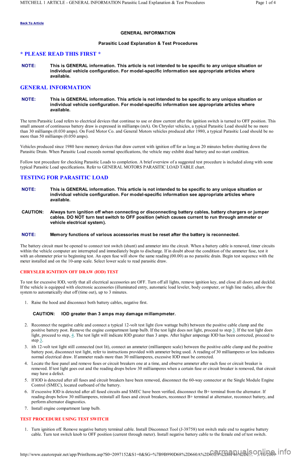
The term Parasitic Load refers to electrical devices that continue to use or draw current after the ignition switch is turned to OFF position. This
small amount of continuous battery draw is expressed in milliamps (mA). On Chrysler vehicles, a typical Parasitic Load should be no more
than 30 milliamps (0.030 amps). On Ford Motor Co. and General Motors vehicles produced after 1980, a typical Parasitic Load should be no
more than 50 milliamps (0.050 amps).
Vehicles produced since 1980 have memory devices that draw current with ignition off for as long as 20 minutes before shutting down the
Parasitic Drain. When Parasitic Load exceeds normal specifications, the vehicle may exhibit dead battery and no-start condition.
Follow test procedure for checking Parasitic Loads to completion. A brief overview of a suggested test procedure is included along with some
typical Parasitic Load specifications. Refer to GENERAL MOTORS PARASITIC LOAD TABLE chart.
TESTING FOR PARASITIC LOAD
The battery circuit must be opened to connect test switch (shunt) and ammeter into the circuit. When a battery cable is removed, timer circuits
within the vehicle computer are interrupted and immediately begin to discharge. If in doubt about the condition of the ammeter fuse, test it
with an ohmmeter prior to beginning test. An open fuse will show the same reading (00.00) as no parasitic drain. Begin test sequence with the
meter installed and on the 10-amp scale. Select lower scale to read parasitic draw.
CHRYSLER IGNITION OFF DRAW (IOD) TEST
To test for excessive IOD, verify that all electrical accessories are OFF. Turn off all lights, remove ignition key, and close all doors and decklid.
If the vehicle is equipped with electronic accessories (illuminated entry, automatic load leveler, body computer, or high line radio), allow the
system to automatically shut off (time out), up to 3 minutes.
1. Raise the hood and disconnect both battery cables, negative first.
2. Reconnect the negative cable and connect a typical 12-volt test light (low wattage bulb) between the positive cable clamp and the
positive battery post. Remove the engine compartment lamp bulb. If the test light does not light, proceed to step 3
. If the test light does
light, proceed to step, 4
. The test light will indicate IOD greater than 3 amps. After higher amperage IOD has been corrected, proceed to
step 3
.
3. ith 12-volt test light still connected (not lit), connect an ammeter (milliampere scale) between the positive cable clamp and the positive
battery post, disconnect test light, refer to instructions provided with ammeter being used. A reading of 30 milliamperes or less indicates
normal electrical draw. If ammeter reads more than 30 milliamperes, excessive IOD must be corrected.
4. Locate the fuse panel and remove fuses or circuit breakers one at a time, and observe ammeter after each fuse or circuit breaker is
removed. If test light goes out and the reading drops below 30 milliamperes when a certain fuse or circuit breaker is removed, that circuit
may have a defect.
5. If IOD is detected after all fuses and circuit breakers have been removed, disconnect the 60-way connector at the Single Module Engine
Control (SMEC), located outboard of the battery.
6. If excessive IOD is detected after all fused circuits and SMEC have been verified, disconnect the B+ terminal from the alternat o r. If
reading drops below 30 milliamperes, reinstall all fuses and circuit breakers, reconnect B+ terminal at alternator, reconnect battery, and
perform alternator diagnostics.
7. Install engine compartment lamp bulb.
TEST PROCEDURE USING TEST SWITCH
1. Turn ignition off. Remove negative battery terminal cable. Install Disconnect Tool (J-38758) test switch male end to negative battery
cable. Turn test switch knob to OFF position (current through meter). Install negative battery cable to the female end of test switch. NOTE:This is GENERAL inform ation. This article is not intended to be specific to any unique situation or
individual vehicle configuration. For m odel-specific inform ation see appropriate articles where
available.
NOTE:This is GENERAL inform ation. This article is not intended to be specific to any unique situation or
individual vehicle configuration. For m odel-specific inform ation see appropriate articles where
available.
NOTE:This is GENERAL inform ation. This article is not intended to be specific to any unique situation or
individual vehicle configuration. For m odel-specific inform ation see appropriate articles where
available.
CAUT ION: Always turn ignition off when connecting or disconnecting battery cables, battery chargers or jum per
cables. DO NOT turn test switch to OFF position (which causes current to run through am m eter or
vehicle electrical system ).
NOTE:Mem ory functions of various accessories m ust be reset after the battery is reconnected.
CAUT ION: IOD greater than 3 am ps m ay dam age m illam pm eter.
Page 1 of 4 MITCHELL 1 ARTICLE - GENERAL INFORMATION Parasitic Load Explanation & Test Procedures
3/10/2009 http://www.eautorepair.net/app/PrintItems.asp?S0=2097152&S1=0&SG=%7B9B990D68%2D660A%2D45E9%2D8F46%2DE
...
Page 279 of 454
2. Turn test switch knob to ON position (current through switch). Road test vehicle with vehicle accessories on (radio, air conditioner, etc).
After road test, turn ignition switch to LOCKED position and remove key. Connect ammeter terminals to test switch terminals. See Fig.
1. Select 10-amp scale.
3. Turn off all electrical accessories. Turn off interior lights, underhood lamp, trunk light, illuminated entry, etc. To avoid damaging
ammeter or obtaining a false meter reading, all accessories must be off before turning test switch knob to OFF position.
4. Turn test switch knob to OFF position to allow current to flow through ammeter. If meter reads wrong polarity, turn test switch to ON
position and reverse leads. Turn test switch to OFF position. Observe current reading. If reading is less than 2 amps, turn test switch to
ON position to keep electrical circuits powered-up.
5. Select low amp scale. Switch lead to the correct meter position. Turn test switch to OFF position and compare results to normal current
draw. See GENERAL MOTORS PARASITIC LOAD TABLE (MILLIAMPS)
. If current draw is unusually high for the vehicle's
overall electrical system, remove system fuses one at a time until current draw returns to normal.
6. Turn test switch to ON position each time door is opened or fuse is removed. Turn switch to OFF position to read current draw va l u e
through meter. When the cause of excessive current drain has been located and repaired, remove test switch and reconnect negative
battery cable to the negative battery terminal.
INTERMITTENT PARASITIC LOAD PROBLEMS
Intermittent parasitic load can occur because of a memory device that does not power down with ignition off. With an intermittent parasitic
load, battery draw can be greater than 1.0 amp.
To find an intermittent problem requires that an ammeter and Disconnect Tool (J-38758) test switch be connected and left in the circuit. See
Fig. 1
. Road test vehicle. After road test, turn ignition off and remove key.
Monitor the milliamps scale for 15-20 minutes after ignition is turned off. This allows monitoring memory devices to determine if they time out
and stop drawing memory current. The test switch is needed to protect ammeter when the vehicle is started.
Fig. 1: Connecting Kent
-Moore Disconnect Tool (J-38758)
Courtesy of GENERAL MOTORS CORP.
GENERAL MOTORS PARASITIC LOAD
ComponentNormal DrawMaximum DrawTime-Out (Minutes)
Anti-Theft System0.41.0.....
Auto Door Lock1.01.0.....
Body Control Module3.612.420
Central Processing System1.62.720
Electronic Control Module5.610.0.....
Electronic Level Control2.03.320
Heated Windshield Module0.30.4.....
HVAC Power Module1.01.0.....
Illuminated Entry1.01.01
Light Control Module0.51.0.....
Oil Level Module0.10.1.....
Page 2 of 4 MITCHELL 1 ARTICLE - GENERAL INFORMATION Parasitic Load Explanation & Test Procedures
3/10/2009 http://www.eautorepair.net/app/PrintItems.asp?S0=2097152&S1=0&SG=%7B9B990D68%2D660A%2D45E9%2D8F46%2DE
...
Page 280 of 454
DIODE CHECK & SOLENOID TEST
Fig. 2: Diode Check & Solenoid Test
Courtesy of GENERAL MOTORS CORP.
QUAD DRIVER TEST
Fig. 3: Quad Driver Test
Courtesy of GENERAL MOTORS CORP.
Multi-Function Chime1.01.0.....
Pass Key Decoder Module0.751.0.....
Power Control Module5.07.0.....
Retained Accessory Power3.83.8.....
Radio7.08.015
Twilight Sentinel Module1.01.0.....
Voltage Regulator1.42.0.....
Page 3 of 4 MITCHELL 1 ARTICLE - GENERAL INFORMATION Parasitic Load Explanation & Test Procedures
3/10/2009 http://www.eautorepair.net/app/PrintItems.asp?S0=2097152&S1=0&SG=%7B9B990D68%2D660A%2D45E9%2D8F46%2DE
...