belt FORD FESTIVA 1991 Service Manual
[x] Cancel search | Manufacturer: FORD, Model Year: 1991, Model line: FESTIVA, Model: FORD FESTIVA 1991Pages: 454, PDF Size: 9.53 MB
Page 2 of 454
Back To Article
INST RUMENT PANEL
1991 ACCESSORIES & SAFET Y EQUIPMENT Ford Motor Co. Switches & Instrum ent Panels - Standard
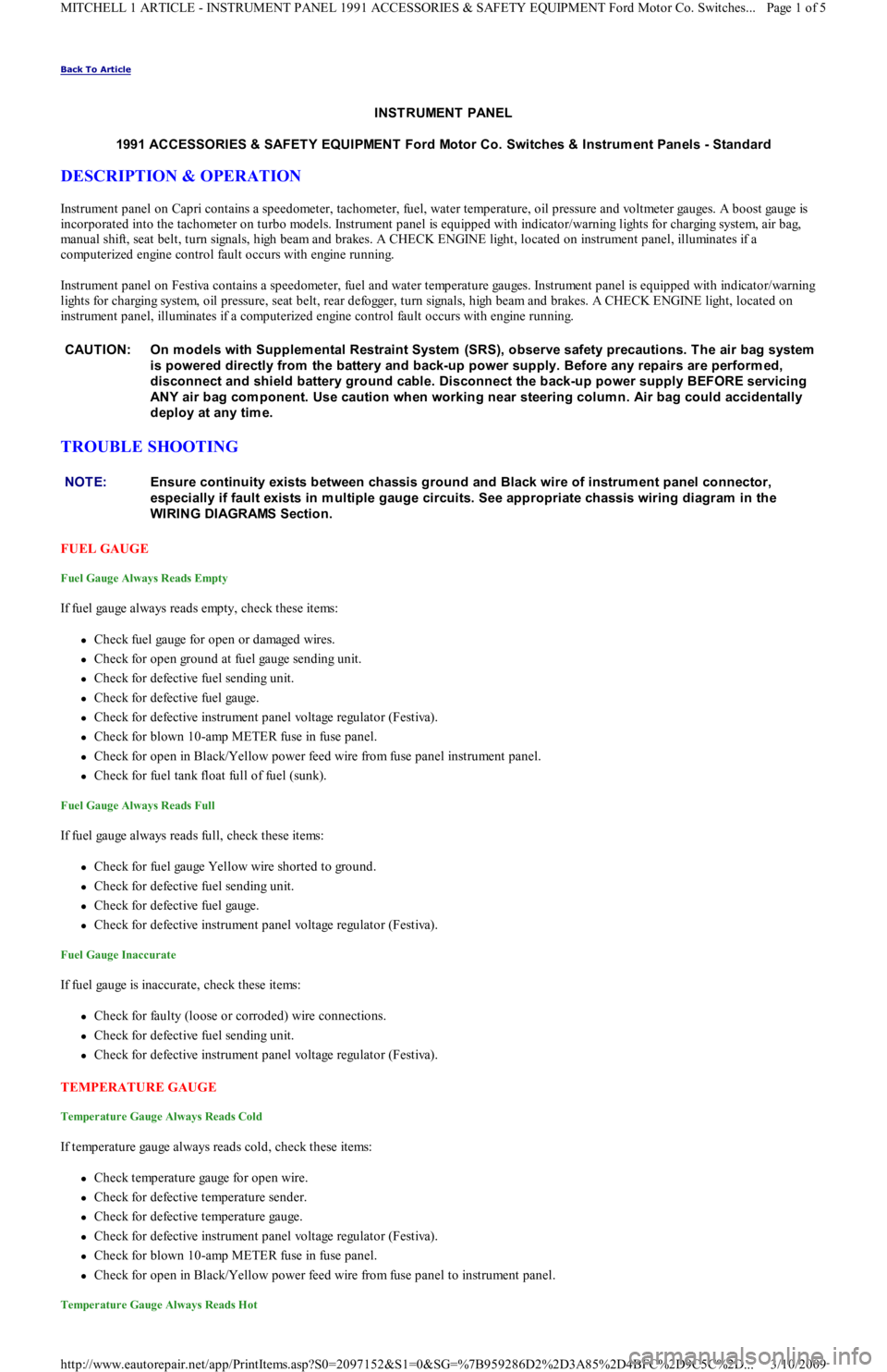
DESCRIPTION & OPERATION
Instrument panel on Capri contains a speedometer, tachometer, fuel, water temperature, oil pressure and voltmeter gauges. A boost gauge is
incorporated into the tachometer on turbo models. Instrument panel is equipped with indicator/warning lights for charging system, air b ag,
manual shift, seat belt, turn signals, high beam and brakes. A CHECK ENGINE light, located on instrument panel, illuminates if a
computerized engine control fault occurs with engine running.
Instrument panel on Festiva contains a speedometer, fuel and water temperature gauges. Instrument panel is equipped with indicator/warning
lights for charging system, oil pressure, seat belt, rear defogger, turn signals, high beam and brakes. A CHECK ENGINE light, located on
instrument panel, illuminates if a computerized engine control fault occurs with engine running.
TROUBLE SHOOTING
FUEL GAUGE
Fuel Gauge Always Reads Empty
If fuel gauge always reads empty, check these items:
Check fuel gauge for open or damaged wires.
Check for open ground at fuel gauge sending unit.
Check for defective fuel sending unit.
Check for defective fuel gauge.
Check for defective instrument panel voltage regulator (Festiva).
Check for blown 10-amp METER fuse in fuse panel.
Check for open in Black/Yellow power feed wire from fuse panel instrument panel.
Check for fuel tank float full of fuel (sunk).
Fuel Gauge Always Reads Full
If fuel gauge always reads full, check these items:
Check for fuel gauge Yellow wire shorted to ground.
Check for defective fuel sending unit.
Check for defective fuel gauge.
Check for defective instrument panel voltage regulator (Festiva).
Fuel Gauge Inaccurate
If fuel gauge is inaccurate, check these items:
Check for faulty (loose or corroded) wire connections.
Check for defective fuel sending unit.
Check for defective instrument panel voltage regulator (Festiva).
TEMPERATURE GAUGE
Temperature Gauge Always Reads Cold
If temperature gauge always reads cold, check these items:
Check temperature gauge for open wire.
Check for defective temperature sender.
Check for defective temperature gauge.
Check for defective instrument panel voltage regulator (Festiva).
Check for blown 10-amp METER fuse in fuse panel.
Check for open in Black/Yellow power feed wire from fuse panel to instrument panel.
Temperature Gauge Always Reads Hot
CAUT ION: On m odels with Supplem ental Restraint System (SRS), observe safety precautions. T he air bag system
is powered directly from the battery and back-up power supply. Before any repairs are perform ed,
disconnect and shield battery ground cable. Disconnect the back-up power supply BEFORE servicing
ANY air bag com ponent. Use caution when working near steering colum n. Air bag could accidentally
deploy at any tim e.
NOTE:Ensure continuity exists between chassis ground and Black wire of instrum ent panel connector,
especially if fault exists in m ultiple gauge circuits. See appropriate chassis wiring diagram in the
WIRING DIAGRAMS Section.
Page 1 of 5 MITCHELL 1 ARTICLE - INSTRUMENT PANEL 1991 ACCESSORIES & SAFETY EQUIPMENT Ford Motor Co. Switches
...
3/10/2009 http://www.eautorepair.net/app/PrintItems.asp?S0=2097152&S1=0&SG=%7B959286D2%2D3A85%2D4BFC%2D9C5C%2D
...
Page 43 of 454
Back To Article
ALTERNATOR & REGULATOR
1991 ELECT RICAL Alternators & Regulators
DESCRIPTION
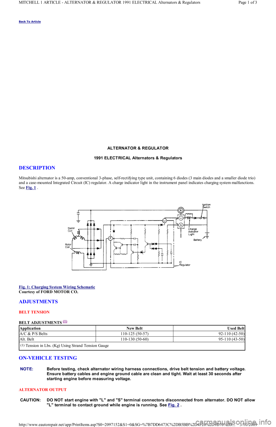
Mitsubishi alternator is a 50-amp, conventional 3-phase, self-rectifying type unit, containing 6 diodes (3 main diodes and a smaller diode trio)
and a case-mounted Integrated Circuit (IC) regulator. A charge indicator light in the instrument panel indicates charging system mal fu n ct io n s.
See Fig. 1
.
Fig. 1: Charging System Wiring Schematic
Courtesy of FORD MOTOR CO.
ADJUSTMENTS
BELT TENSION
BELT ADJUSTMENTS
(1)
ON-VEHICLE TESTING
ALTERNATOR OUTPUT
ApplicationNew BeltUsed Belt
A/C & P/S Belts110-125 (50-57)92-110 (42-50)
Alt. Belt110-130 (50-60)95-110 (43-50)
(1)Tension in Lbs. (Kg) Using Strand Tension Gauge
NOTE:Before testing, check alternator wiring harness connections, drive belt tension and battery voltage.
Ensure battery cables and engine ground cable are clean and tight. Wait at least 30 seconds after
starting engine before m easuring voltage.
CAUT ION: DO NOT start engine with "L" and "S" term inal connectors disconnected from alternator. DO NOT allow
"L" term inal to contact ground while engine is running. See Fig. 2
.
Page 1 of 3 MITCHELL 1 ARTICLE - ALTERNATOR & REGULATOR 1991 ELECTRICAL Alternators & Regulators
3/10/2009 http://www.eautorepair.net/app/PrintItems.asp?S0=2097152&S1=0&SG=%7B7DD6473C%2DB5BB%2D4F20%2D9D70%2D
...
Page 47 of 454
SOLENOIDS & SOLENOID VALVES
SOLENOIDS & SOLENOID VALVES LOCATION
SWITCHES
SWITCHES LOCATION
MISCELLANEOUS
MISCELLANEOUS LOCATION
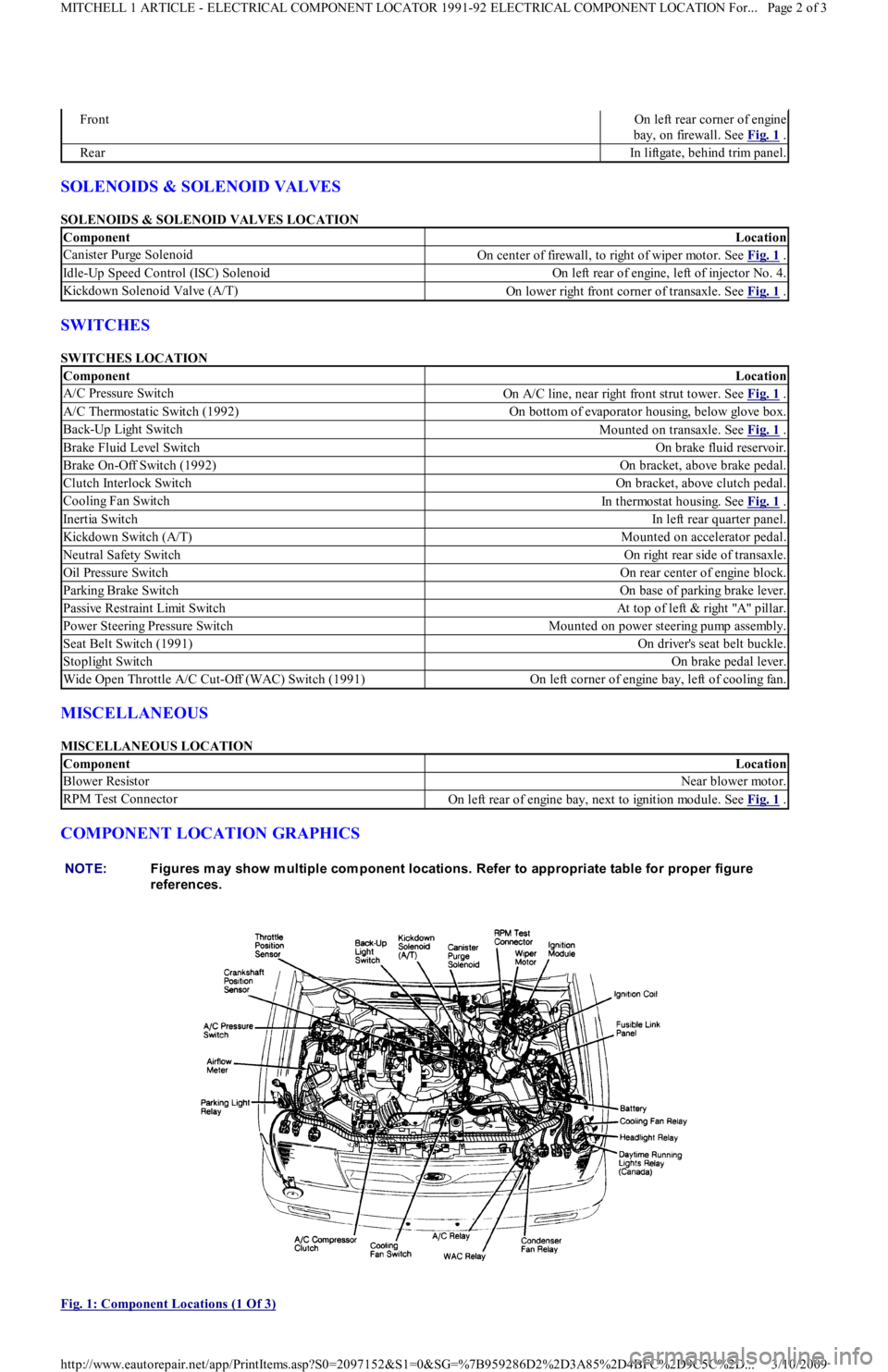
COMPONENT LOCATION GRAPHICS
Fig. 1: Component Locations (1 Of 3)
FrontOn left rear corner of engine
bay, on firewall. See Fig. 1
.
RearIn liftgate, behind trim panel.
ComponentLocation
Canister Purge SolenoidOn center of firewall, to right of wiper motor. See Fig. 1 .
Idle-Up Speed Control (ISC) SolenoidOn left rear of engine, left of injector No. 4.
Kickdown Solenoid Valve (A/T)On lower right front corner of transaxle. See Fig. 1 .
ComponentLocation
A/C Pressure SwitchOn A/C line, near right front strut tower. See Fig. 1 .
A/C Thermostatic Switch (1992)On bottom of evaporator housing, below glove box.
Back-Up Light SwitchMounted on transaxle. See Fig. 1 .
Brake Fluid Level SwitchOn brake fluid reservoir.
Brake On-Off Switch (1992)On bracket, above brake pedal.
Clutch Interlock SwitchOn bracket, above clutch pedal.
Cooling Fan SwitchIn thermostat housing. See Fig. 1 .
Inertia SwitchIn left rear quarter panel.
Kickdown Switch (A/T)Mounted on accelerator pedal.
Neutral Safety SwitchOn right rear side of transaxle.
Oil Pressure SwitchOn rear center of engine block.
Parking Brake SwitchOn base of parking brake lever.
Passive Restraint Limit SwitchAt top of left & right "A" pillar.
Power Steering Pressure SwitchMounted on power steering pump assembly.
Seat Belt Switch (1991)On driver's seat belt buckle.
Stoplight SwitchOn brake pedal lever.
Wide Open Throttle A/C Cut-Off (WAC) Switch (1991)On left corner of engine bay, left of cooling fan.
ComponentLocation
Blower ResistorNear blower motor.
RPM Test ConnectorOn left rear of engine bay, next to ignition module. See Fig. 1 .
NOTE:Figures m ay show m ultiple com ponent locations. Refer to appropriate table for proper figure
references.
Page 2 of 3 MITCHELL 1 ARTICLE - ELECTRICAL COMPONENT LOCATOR 1991-92 ELECTRICAL COMPONENT LOCATION For...
3/10/2009 http://www.eautorepair.net/app/PrintItems.asp?S0=2097152&S1=0&SG=%7B959286D2%2D3A85%2D4BFC%2D9C5C%2D
...
Page 49 of 454
Back To Article
FUSES & CIRCUIT BREAKERS
Fuses & Circuit Breakers 1988-93 Festiva
FUSES & FUSIBLE LINKS
FUSE PANEL & FUSIBLE LINK BLOCK LOCATIONS
The vehicle has a fuse block with fusible links and a fuse panel with circuit fuses. The fuse panel is located behind the instrument panel, left o
f
the steering column. The fuse block is located under the hood.
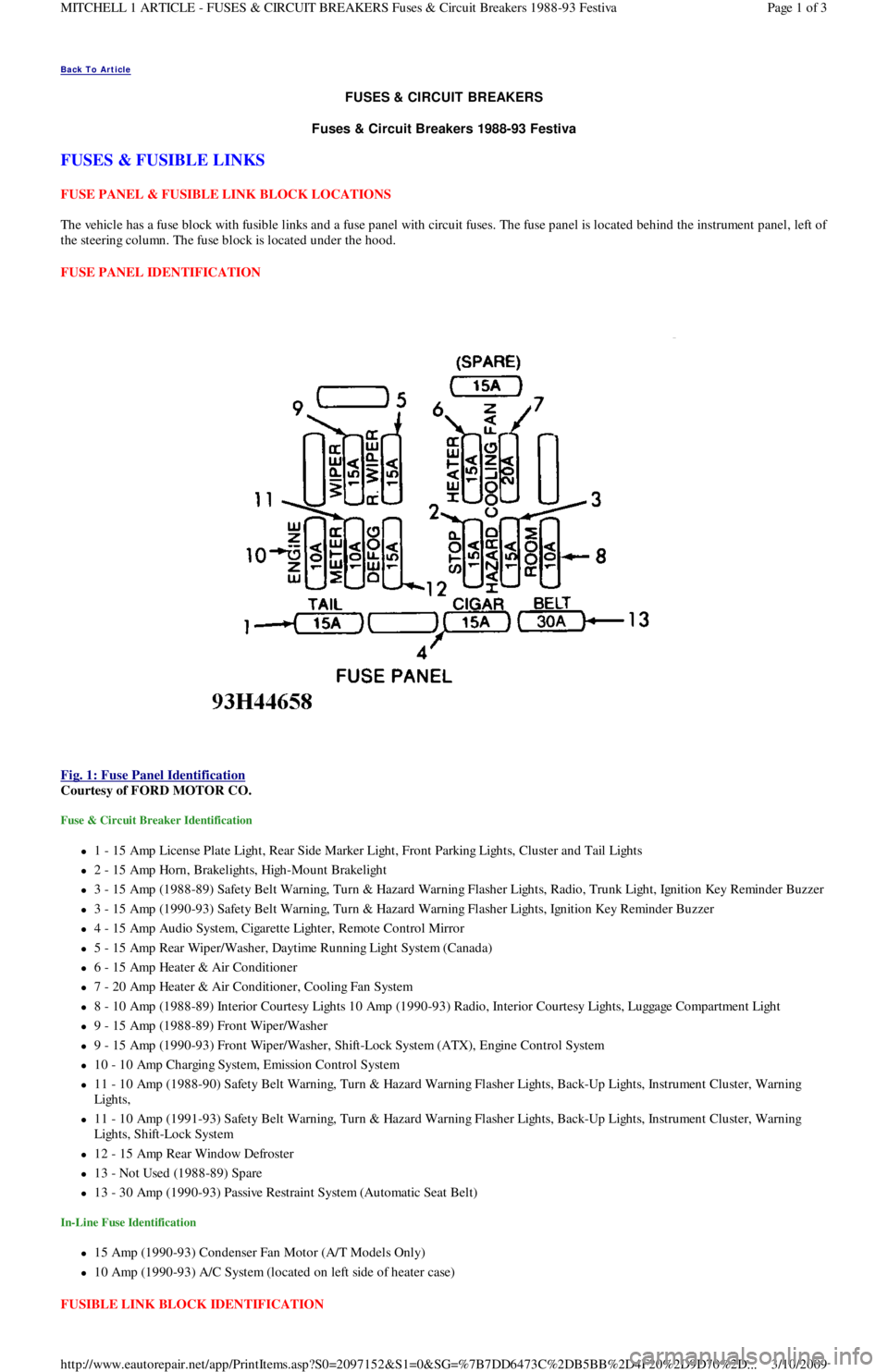
FUSE PANEL IDENTIFICATION
Fig. 1: Fuse Panel Identification
Courtesy of FORD MOTOR CO.
Fuse & Circuit Breaker Identification
1 - 15 Amp License Plate Light, Rear Side Marker Ligh t , Fr o n t P a r kin g Ligh t s, C l u st e r a n d Ta il Ligh t s
2 - 15 Amp Horn, Brakelights, High-Mount Brakelight
3 - 15 Amp (1988-89) Safety Belt Warning, Turn & Hazard Warning Flasher Lights, Radio, Trunk Light, Ignition Key Reminder Buzzer
3 - 15 Amp (1990-93) Safety Belt Warning, Turn & Hazard Warning Flasher Lights, Ignition Key Reminder Buzzer
4 - 15 Amp Audio System, Cigarette Lighter, Remote Control Mirror
5 - 15 Amp Rear Wiper/Washer, Daytime Running Light System (Canada)
6 - 15 Amp Heater & Air Conditioner
7 - 20 Amp Heater & Air Conditioner, Cooling Fan System
8 - 10 Amp (1988-89) Interior Courtesy Lights 10 Amp (1990-93) Radio, Interior Courtesy Lights, Luggage Compartment Light
9 - 15 Amp (1988-89) Front Wiper/Washer
9 - 15 Amp (1990-93) Front Wiper/Washer, Shift-Lock System (ATX), Engine Control System
10 - 10 Amp Charging System, Emission Control System
11 - 10 Amp (1988-90) Safety Belt Warning, Turn & Hazard Warning Flasher Lights, Back-Up Lights, Instrument Cluster, Warning
Lights,
11 - 10 Amp (1991-93) Safety Belt Warning, Turn & Hazard Warning Flasher Lights, Back-Up Lights, Instrument Cluster, Warning
Lights, Shift-Lock System
12 - 15 Amp Rear Window Defroster
13 - Not Used (1988-89) Spare
13 - 30 Amp (1990-93) Passive Restraint System (Automatic Seat Belt)
In-Line Fuse Identification
15 Amp (1990-93) Condenser Fan Motor (A/T Models Only)
10 Amp (1990-93) A/C System (located on left side of heater case)
FUSIBLE LINK BLOCK IDENTIFICATION
Page 1 of 3 MITCHELL 1 ARTICLE - FUSES & CIRCUIT BREAKERS Fuses & Circuit Breakers 1988-93 Festiva
3/10/2009 http://www.eautorepair.net/app/PrintItems.asp?S0=2097152&S1=0&SG=%7B7DD6473C%2DB5BB%2D4F20%2D9D70%2D
...
Page 67 of 454
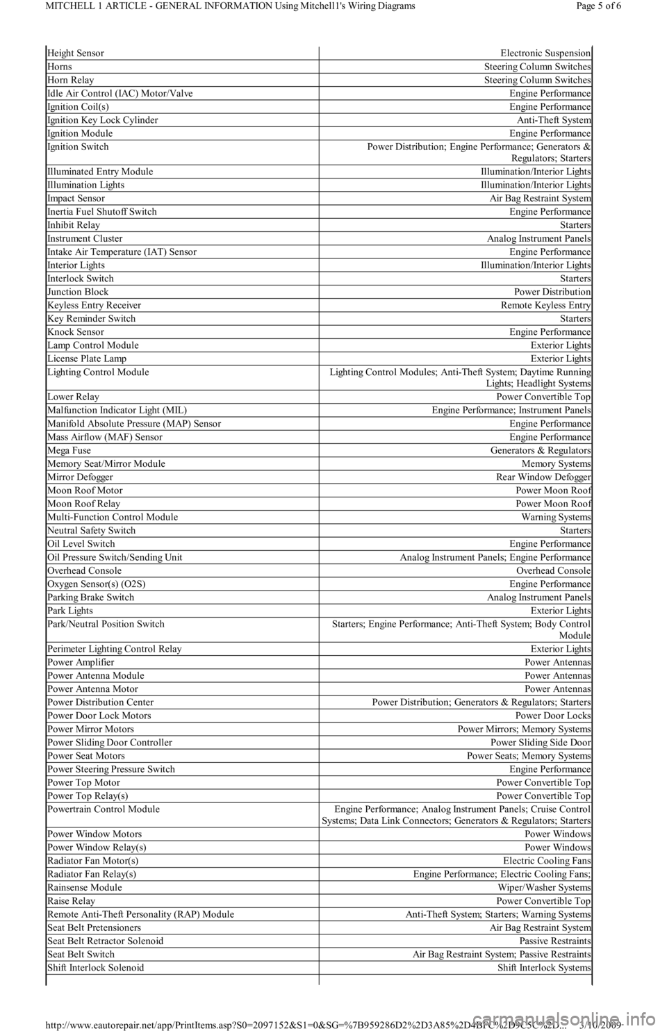
Height SensorElectronic Suspension
HornsSteering Column Switches
Horn RelaySteering Column Switches
Idle Air Control (IAC) Motor/ValveEngine Performance
Ignition Coil(s)Engine Performance
Ignition Key Lock CylinderAnti-Theft System
Ignition ModuleEngine Performance
Ignition SwitchPower Distribution; Engine Performance; Generators &
Regulators; Starters
Illuminated Entry ModuleIllumination/Interior Lights
Illumination LightsIllumination/Interior Lights
Impact SensorAir Bag Restraint System
Inertia Fuel Shutoff SwitchEngine Performance
In h ib it Rel ayStarters
Instrument ClusterAnalog Instrument Panels
Intake Air Temperature (IAT) SensorEngine Performance
Interior LightsIllumination/Interior Lights
In t erl o ck Swit chStarters
Junction BlockPower Distribution
Keyless Entry ReceiverRemote Keyless Entry
Key Reminder SwitchStarters
Knock SensorEngine Performance
Lamp Control ModuleExterior Lights
License Plate LampExterior Lights
Lighting Control ModuleLighting Control Modules; Anti-Theft System; Daytime Running
Lights; Headlight Systems
Lower RelayPower Convertible Top
Malfunction Indicator Light (MIL)Engine Performance; Instrument Panels
Manifold Absolute Pressure (MAP) SensorEngine Performance
Mass Airflow (MAF) SensorEngine Performance
Mega FuseGenerators & Regulators
Memory Seat/Mirror ModuleMemory Systems
M ir r o r De fo gge rRear Window Defogger
Moon Roof MotorPower Moon Roof
Moon Roof RelayPower Moon Roof
Multi-Function Control ModuleWarning Systems
Neutral Safety SwitchStarters
Oil Level SwitchEngine Performance
Oil Pressure Switch/Sending UnitAnalog Instrument Panels; Engine Performance
Overhead ConsoleOverhead Console
Oxygen Sensor(s) (O2S)Engine Performance
Parking Brake SwitchAnalog Instrument Panels
Park LightsExterior Lights
Park/Neutral Position SwitchStarters; Engine Performance; Anti-Theft System; Body Control
Module
Perimeter Lighting Control RelayExterior Lights
Power AmplifierPower Antennas
Power Antenna ModulePower Antennas
Power Antenna MotorPower Antennas
Power Distribution CenterPower Distribution; Generators & Regulators; Starters
Power Door Lock MotorsPower Door Locks
Power Mirror MotorsPower Mirrors; Memory Systems
Power Sliding Door ControllerPower Sliding Side Door
Power Seat MotorsPower Seats; Memory Systems
Power Steering Pressure SwitchEngine Performance
Power Top MotorPower Convertible Top
Power Top Relay(s)Power Convertible Top
Powertrain Control ModuleEngine Performance; Analog Instrument Panels; Cruise Control
Systems; Data Link Connectors; Generators & Regulators; Starters
Power Window MotorsPower Windows
Power Window Relay(s)Power Windows
Radiator Fan Motor(s)Electric Cooling Fans
Radiator Fan Relay(s)Engine Performance; Electric Cooling Fans;
Rainsense ModuleWiper/Washer Systems
Raise RelayPower Convertible Top
Remote Anti-Theft Personality (RAP) ModuleAnti-Theft System; Starters; Warning Systems
Seat Belt PretensionersAir Bag Restraint System
Seat Belt Retractor SolenoidPassive Restraints
Seat Belt SwitchAir Bag Restraint System; Passive Restraints
Shift Interlock SolenoidShift Interlock Systems
Page 5 of 6 MITCHELL 1 ARTICLE - GENERAL INFORMATION Using Mitchell1's Wiring Diagrams
3/10/2009 http://www.eautorepair.net/app/PrintItems.asp?S0=2097152&S1=0&SG=%7B959286D2%2D3A85%2D4BFC%2D9C5C%2D
...
Page 75 of 454
Back To Article
DRIVE BELT ROUTING
1991-92 ENGINE COOLING BELT ROUT ING
BELT ADJUSTMENT
Tensioners may be used to automatically adjust belt tension to specification. Check belt for fraying. If fraying exists, ensure both belt and
tensioner are properly aligned. See Fig. 1
. Tensioners may contain a belt-wear indicator. See Fig. 2 . If tensioner reaches travel limit, as
indicated by marks on tensioner, replace belt. Ensure serpentine belts are properly installed. See Fig. 3
-Fig. 7 . On models without
tensioners, ensure belt tension is within specification. See BELT ADJUSTMENT SPECIFICATIONS table.
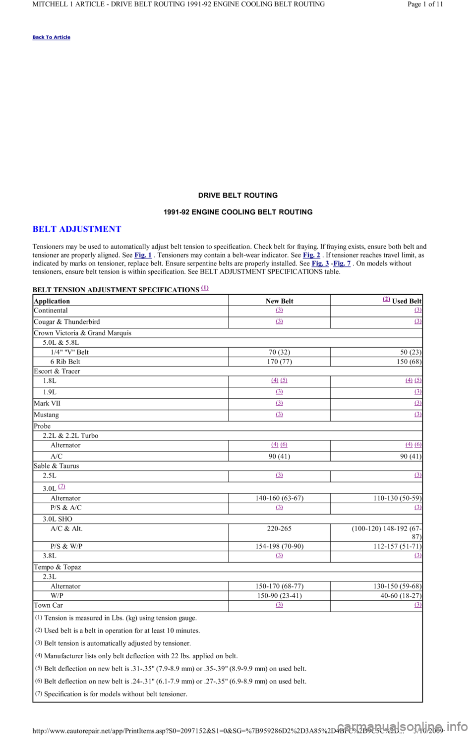
BELT TENSION ADJUSTMENT SPECIFICATIONS
(1)
ApplicationNew Belt(2) Used Belt
Continental(3) (3)
Cougar & Thunderbird(3) (3)
Crown Victoria & Grand Marquis
5.0L & 5.8L
1/4" "V" Belt70 (32)50 (23)
6 Rib Belt170 (77)150 (68)
Escort & Tracer
1.8L(4) (5) (4) (5)
1.9L(3) (3)
Mark VII(3) (3)
Mustang(3) (3)
Probe
2.2L & 2.2L Turbo
Alternator(4) (6) (4) (6)
A/C90 (41)90 (41)
Sable & Taurus
2.5L(3) (3)
3.0L (7)
Alternator140-160 (63-67)110-130 (50-59)
P/S & A/C(3) (3)
3.0L SHO
A/C & Alt.220-265(100-120) 148-192 (67-
87)
P/S & W/P154-198 (70-90)112-157 (51-71)
3.8L(3) (3)
Tempo & Topaz
2.3L
Alternator150-170 (68-77)130-150 (59-68)
W/P150-90 (23-41)40-60 (18-27)
Town Car(3) (3)
(1)Tension is measured in Lbs. (kg) using tension gauge.
(2)Used belt is a belt in operation for at least 10 minutes.
(3)Belt tension is automatically adjusted by tensioner.
(4)Manufacturer lists only belt deflection with 22 lbs. applied on belt.
(5)Belt deflection on new belt is .31-.35" (7.9-8.9 mm) or .35-.39" (8.9-9.9 mm) on used belt.
(6)Belt deflection on new belt is .24-.31" (6.1-7.9 mm) or .27-.35" (6.9-8.9 mm) on used belt.
(7)Specification is for models without belt tensioner.
Page 1 of 11 MITCHELL 1 ARTICLE - DRIVE BELT ROUTING 1991-92 ENGINE COOLING BELT ROUTING
3/10/2009 http://www.eautorepair.net/app/PrintItems.asp?S0=2097152&S1=0&SG=%7B959286D2%2D3A85%2D4BFC%2D9C5C%2D
...
Page 76 of 454
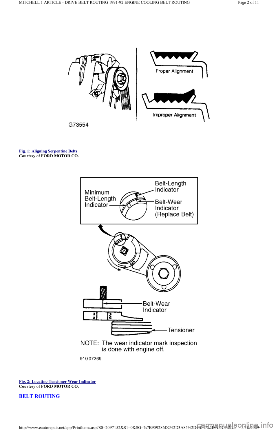
Fig. 1: Aligning Serpentine Belts
Courtesy of FORD MOTOR CO.
Fig. 2: Locating Tensioner Wear Indicator
Courtesy of FORD MOTOR CO.
BELT ROUTING
Page 2 of 11 MITCHELL 1 ARTICLE - DRIVE BELT ROUTING 1991-92 ENGINE COOLING BELT ROUTING
3/10/2009 http://www.eautorepair.net/app/PrintItems.asp?S0=2097152&S1=0&SG=%7B959286D2%2D3A85%2D4BFC%2D9C5C%2D
...
Page 77 of 454
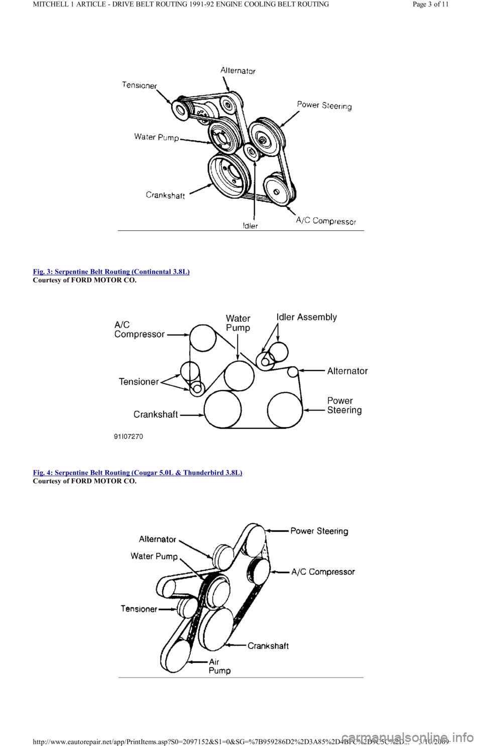
Fig. 3: Serpentine Belt Routing (Continental 3.8L)
Courtesy of FORD MOTOR CO.
Fig. 4: Serpentine Belt Routing (Cougar 5.0L & Thunderbird 3.8L)
Courtesy of FORD MOTOR CO.
Page 3 of 11 MITCHELL 1 ARTICLE - DRIVE BELT ROUTING 1991-92 ENGINE COOLING BELT ROUTING
3/10/2009 http://www.eautorepair.net/app/PrintItems.asp?S0=2097152&S1=0&SG=%7B959286D2%2D3A85%2D4BFC%2D9C5C%2D
...
Page 78 of 454
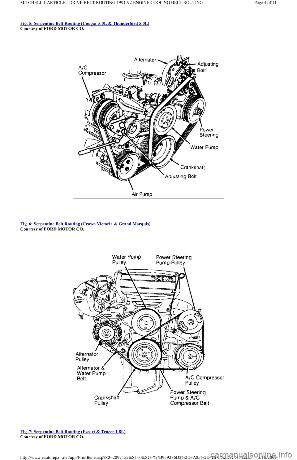
Fig. 5: Serpentine Belt Routing (Cougar 5.0L & Thunderbird 5.0L)
Courtesy of FORD MOTOR CO.
Fig. 6: Serpentine Belt Routing (Crown Victoria & Grand Marquis)
Courtesy of FORD MOTOR CO.
Fig. 7: Serpentine Belt Routing (Escort & Tracer 1.8L)
Courtesy of FORD MOTOR CO.
Page 4 of 11 MITCHELL 1 ARTICLE - DRIVE BELT ROUTING 1991-92 ENGINE COOLING BELT ROUTING
3/10/2009 http://www.eautorepair.net/app/PrintItems.asp?S0=2097152&S1=0&SG=%7B959286D2%2D3A85%2D4BFC%2D9C5C%2D
...
Page 79 of 454
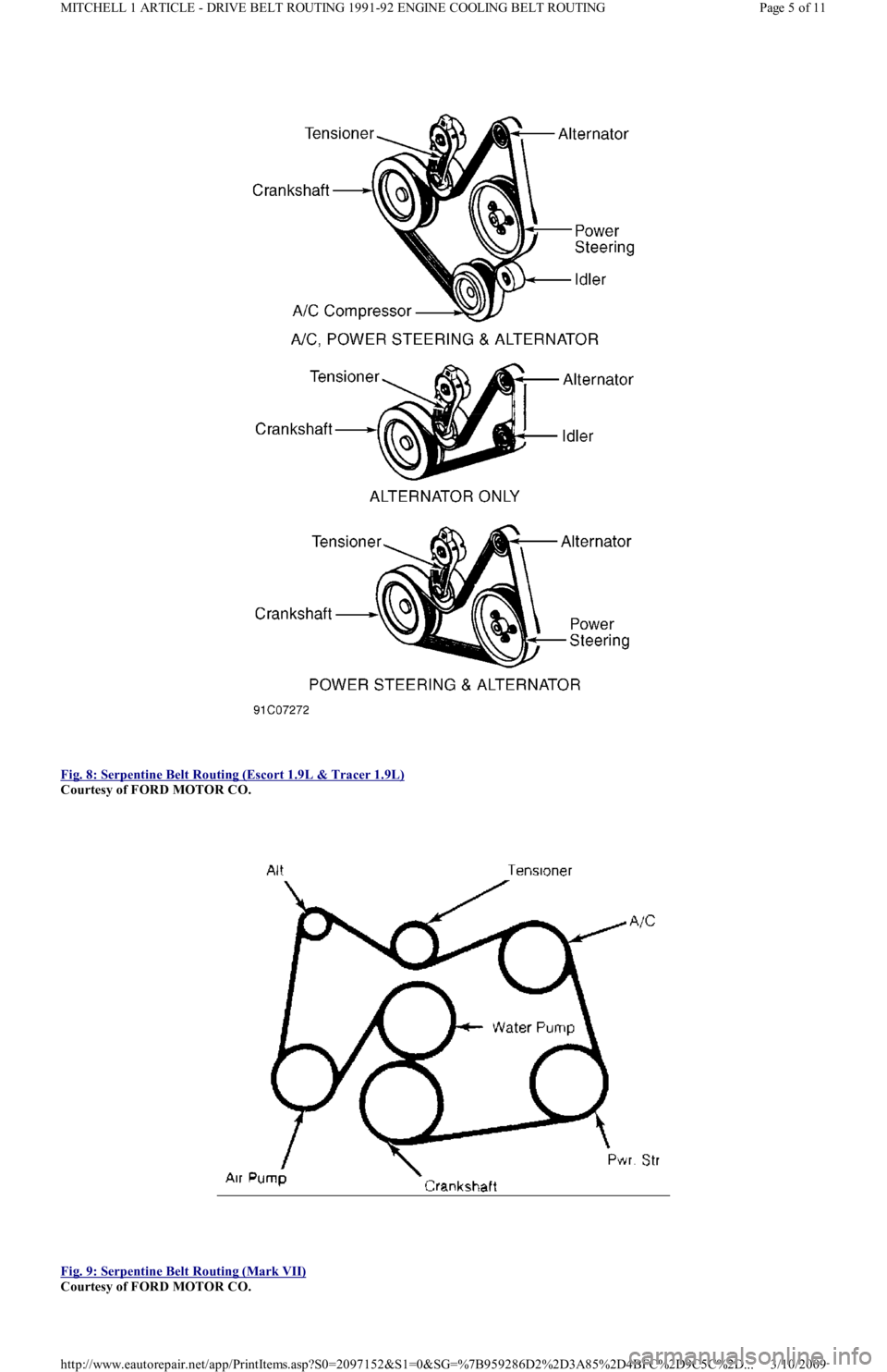
Fig. 8: Serpentine Belt Routing (Escort 1.9L & Tracer 1.9L)
Courtesy of FORD MOTOR CO.
Fig. 9: Serpentine Belt Routing (Mark VII)
Courtesy of FORD MOTOR CO.
Page 5 of 11 MITCHELL 1 ARTICLE - DRIVE BELT ROUTING 1991-92 ENGINE COOLING BELT ROUTING
3/10/2009 http://www.eautorepair.net/app/PrintItems.asp?S0=2097152&S1=0&SG=%7B959286D2%2D3A85%2D4BFC%2D9C5C%2D
...