wheel bolts FORD FESTIVA 1991 Owner's Manual
[x] Cancel search | Manufacturer: FORD, Model Year: 1991, Model line: FESTIVA, Model: FORD FESTIVA 1991Pages: 454, PDF Size: 9.53 MB
Page 239 of 454
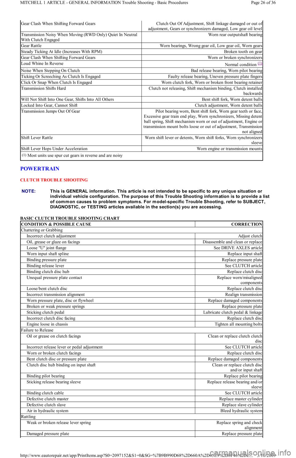
POWERTRAIN
CLUTCH TROUBLE SHOOTING
BASIC CLUTCH TROUBLE SHOOTING CHART
Gear Clash When Shifting Forward GearsClutch Out Of Adjustment, Shift linkage damaged or out of
adjustment, Gears or synchronizers damaged, Low gear oil level
Transmission Noisy When Moving (RWD Only) Quiet In Neutral
With Clutch EngagedWorn rear outputshaft bearing
Gear RattleWorn bearings, Wrong gear oil, Low gear oil, Worn gears
Steady Ticking At Idle (Increases With RPM)Broken tooth on gear
Gear Clash When Shifting Forward GearsWorn or broken synchronizers
Loud Whine In ReverseNormal condition (1)
Noise When Stepping On ClutchBad release bearing, Worn pilot bearing
Ticking Or Screeching As Clutch Is EngagedFaulty release bearing, Uneven pressure plate fingers
Click Or Snap When Clutch Is EngagedWorn clutch fork, Worn or broken front bearing retainer
Transmission Shifts HardClutch not releasing, Shift mechanism binding, Clutch installed
backwards
Will Not Shift Into One Gear, Shifts Into All OthersBent shift fork, Worn detent balls
Locked Into Gear, Cannot ShiftClutch adjustment, Worn detent balls
Transmission Jumps Out Of GearPilot bearing worn, Bent shift fork, Worn gear teeth or face,
Excessive gear train end play, Worn synchronizers, Missing detent
ball spring, Shift mechanism worn or out of adjustment, Engine or
transmission mount bolts loose or out of adjustment, Transmission
not aligned
Shift Lever RattleWorn shift lever or detents, Worn shift forks, Worn synchronizers
sleeve
Shift Lever Hops Under AccelerationWorn engine or transmission mounts
(1)Most units use spur cut gears in reverse and are noisy
NOTE:This is GENERAL inform ation. This article is not intended to be specific to any unique situation or
individual vehicle configuration. T he purpose of this T rouble Shooting inform ation is to provide a list
of com m on causes to problem sym ptom s. For m odel-specific T rouble Shooting, refer to SUBJECT ,
DIAGNOST IC, or T EST ING articles available in the section(s) you are accessing.
CONDITION & POSSIBLE CAUSECORRECTION
Chattering or Grabbing
Incorrect clutch adjustmentAdjust clutch
Oil, grease or glaze on facingsDisassemble and clean or replace
Lo o se "U" jo in t fl an geSee DRIVE AXLES article
Worn input shaft splineReplace input shaft
Binding pressure plateReplace pressure plate
Binding release leverSee CLUTCH article
Binding clutch disc hubReplace clutch disc
Unequal pressure plate contactReplace worn/misaligned
components
Loose/bent clutch discReplace clutch disc
Incorrect transmission alignmentRealign transmission
Worn pressure plate, disc or flywheelReplace damaged components
Broken or weak pressure springsReplace pressure plate
Sticking clutch pedalLubricate clutch pedal & linkage
Incorrect clutch disc facingReplace clutch disc
Engine loose in chassisTighten all mounting bolts
Failure to Release
Oil or grease on clutch facingsClean or replace clutch clutch
disc
Incorrect release lever or pedal adjustmentSee CLUTCH article
Worn or broken clutch facingsReplace clutch disc
Bent clutch disc or pressure plateReplace damaged components
Clutch disc hub binding on input shaftClean or replace clutch disc
and/or input shaft
Binding pilot bearingReplace pilot bearing
Sticking release bearing sleeveReplace release bearing and/or
sleeve
Binding clutch cableSee CLUTCH article
Defective clutch masterReplace master cylinder
Defective clutch slaveReplace slave cylinder
Air in hydraulic systemBleed hydraulic system
Rattling
Weak or broken release lever springReplace spring and check
alignment
Damaged pressure plateReplace pressure plate
Page 26 of 36 MITCHELL 1 ARTICLE - GENERAL INFORMATION Trouble Shooting - Basic Procedures
3/10/2009 http://www.eautorepair.net/app/PrintItems.asp?S0=2097152&S1=0&SG=%7B9B990D68%2D660A%2D45E9%2D8F46%2DE
...
Page 241 of 454
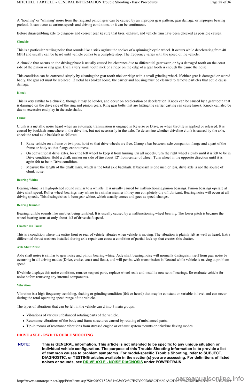
A "howling" or "whining" noise from the ring and pinion gear can be caused by an improper gear pattern, gear damage, or improper bearing
preload. It can occur at various speeds and driving conditions, or it can be continuous.
Before disassembling axle to diagnose and correct gear ke sure that tires, exhaust, and vehicle trim have been checked as possible causes.
Chuckle
This is a particular rattling noise that sounds like a stick against the spokes of a spinning bicycle wheel. It occurs while decelerating from 40
MPH and usually can be heard until vehicle comes to a complete stop. The frequency varies with the speed of the vehicle.
A chuckle that occurs on the driving phase is usually caused ive clearance due to differential gear wear, or by a damaged tooth on the coast
side of the pinion or ring gear. Even a very small tooth nick or a ridge on the edge of a gear tooth is enough the cause the noise.
This condition can be corrected simply by cleaning the gear tooth nick or ridge with a small grinding wheel. If either gear is damaged or scored
badly, the gear set must be replaced. If metal has broken loose, the carrier and housing must be cleaned to remove particles that could cause
damage.
Knock
This is very similar to a chuckle, though it may be louder, and occur on acceleration or deceleration. Knock can be caused by a gear tooth that
is damaged on the drive side of the ring and pinion gears. Ring gear bolts that are hitting the carrier casting can cause knock. Knock can also be
due to excessive end play in the axle shafts.
Clunk
Clunk is a metallic noise heard when an automatic transmission is engaged in Reverse or Drive, or when throttle is applied or released. It is
caused by backlash somewhere in the driveline, but not necessarily in the axle. To determine whether driveline clunk is caused by the axle,
check the total axle backlash as follows:
1. Raise vehicle on a frame or twinpost hoist so that drive wheels are free. Clamp a bar between axle companion flange and a part of the
frame or body so that flange cannot move.
2. On conventional drive axles, lock the left wheel to keep it from turning. On all models, turn the right wheel slowly until it is felt to be in
Drive condition. Hold a chalk marker on side of tire about 12" from center of wheel. Turn wheel in the opposite direction until it is
again felt to be in Drive condition.
3. Measure the length of the chalk mark, which is the total axle backlash. If backlash is one inch or less, drive axle is not the source of
clunk noise.
Bearing Whine
Bearing whine is a high-pitched sound similar to a whistle. It is usually caused by malfunctioning pinion bearings. Pinion bearings operate at
drive shaft speed. Roller wheel bearings may whine in a similar manner if they run completely dry of lubricant. Bearing noise will occur at all
driving speeds. This distinguishes it from gear whine, which usually comes and goes as speed changes.
Bearing Rumble
Bearing rumble sounds like marbles being tumbled. It is usually caused by a malfunctioning wheel bearing. The lower pitch is because the
wheel bearing turns at only about 1/3 of drive shaft speed.
Chatter On Turns
This is a condition where the entire front or rear of vehicle vibrates when vehicle is moving. The vibration is plainly felt as well as heard. Extra
differential thrust washers installed during axle repair can cause a condition of partial lock-up that creates this chatter.
Axle Shaft Noise
Axle shaft noise is similar to gear noise and pinion bearing whine. Axle shaft bearing noise will normally distinguish itself from gear noise by
occurring in all driving modes (Drive, cruise, coast and float), and will persist with transmission in Neutral while vehicle is moving at problem
speed.
If vehicle displays this noise condition, remove suspect parts, replace wheel seals and install a new set of bearings. Re-evaluate vehicle for
noise before removing any internal components.
Vibration
Vibration is a high-frequency trembling, shaking or grinding condition (felt or heard) that may be constant or variable in level and can occur
during the total operating speed range of the vehicle.
The types of vibrations that can be felt in the vehicle can d into 3 main groups:
Vibrations of various unbalanced rotating parts of the vehicle.
Resonance vibrations of the body and frame structures caused by rotating of unbalanced parts.
Tip-in moans of resonance vibrations from stressed engine or exhaust system mounts or driveline flexing modes.
DRIVE AXLE - RWD TROUBLE SHOOTING
NOTE:This is GENERAL inform ation. This article is not intended to be specific to any unique situation or
individual vehicle configuration. T he purpose of this T rouble Shooting inform ation is to provide a list
of com m on causes to problem sym ptom s. For m odel-specific T rouble Shooting, refer to SUBJECT ,
DIAGNOST IC, or T EST ING articles available in the section(s) you are accessing. For definitions of listed
noises or sounds, see DRIVE AXLE
- NOISE DIAGNOSIS under POWERTRAIN.
Page 28 of 36 MITCHELL 1 ARTICLE - GENERAL INFORMATION Trouble Shooting - Basic Procedures
3/10/2009 http://www.eautorepair.net/app/PrintItems.asp?S0=2097152&S1=0&SG=%7B9B990D68%2D660A%2D45E9%2D8F46%2DE
...
Page 242 of 454
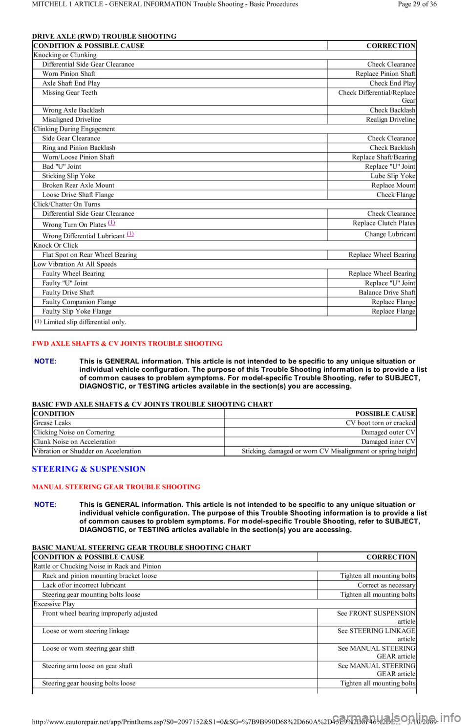
DRIVE AXLE (RWD) TROUBLE SHOOTING
FWD AXLE SHAFTS & CV JOINTS TROUBLE SHOOTING
BASIC FWD AXLE SHAFTS & CV JOINTS TROUBLE SHOOTING CHART
STEERING & SUSPENSION
MANUAL STEERING GEAR TROUBLE SHOOTING
BASIC MANUAL STEERING GEAR TROUBLE SHOOTING CHART
CONDITION & POSSIBLE CAUSECORRECTION
Knocking or Clunking
Differential Side Gear ClearanceCheck Clearance
Worn Pinion ShaftReplace Pinion Shaft
Axle Shaft End PlayCheck End Play
Missing Gear TeethCheck Differential/Replace
Gear
Wrong Axle BacklashCheck Backlash
Misaligned DrivelineRealign Driveline
Clinking During Engagement
Side Gear ClearanceCheck Clearance
Ring and Pinion BacklashCheck Backlash
Worn/Loose Pinion ShaftReplace Shaft/Bearing
Bad "U" JointReplace "U" Joint
Sticking Slip YokeLube Slip Yoke
Broken Rear Axle MountReplace Mount
Loose Drive Shaft FlangeCheck Flange
Click/Chatter On Turns
Differential Side Gear ClearanceCheck Clearance
Wrong Turn On Plates (1)Replace Clutch Plates
Wrong Differential Lubricant (1)Change Lubricant
Knock Or Click
Flat Spot on Rear Wheel BearingReplace Wheel Bearing
Low Vibration At All Speeds
Faulty Wheel BearingReplace Wheel Bearing
Faulty "U" JointReplace "U" Joint
Faulty Drive ShaftBalance Drive Shaft
Faulty Companion FlangeReplace Flange
Faulty Slip Yoke FlangeReplace Flange
(1)Limited slip differential only.
NOTE:This is GENERAL inform ation. This article is not intended to be specific to any unique situation or
individual vehicle configuration. T he purpose of this T rouble Shooting inform ation is to provide a list
of com m on causes to problem sym ptom s. For m odel-specific T rouble Shooting, refer to SUBJECT ,
DIAGNOST IC, or T EST ING articles available in the section(s) you are accessing.
CONDITIONPOSSIBLE CAUSE
Grease LeaksCV boot torn or cracked
Clicking Noise on CorneringDamaged outer CV
Clunk Noise on AccelerationDamaged inner CV
Vibration or Shudder on AccelerationSticking, damaged or worn CV Misalignment or spring height
NOTE:This is GENERAL inform ation. This article is not intended to be specific to any unique situation or
individual vehicle configuration. T he purpose of this T rouble Shooting inform ation is to provide a list
of com m on causes to problem sym ptom s. For m odel-specific T rouble Shooting, refer to SUBJECT ,
DIAGNOST IC, or T EST ING articles available in the section(s) you are accessing.
CONDITION & POSSIBLE CAUSECORRECTION
Rattle or Chucking Noise in Rack and Pinion
Rack and pinion mounting bracket looseTighten all mounting bolts
Lack of/or incorrect lubricantCorrect as necessary
Steering gear mounting bolts looseTighten all mounting bolts
Excessive Play
Front wheel bearing improperly adjustedSee FRONT SUSPENSION
article
Loose or worn steering linkageSee STEERING LINKAGE
article
Loose or worn steering gear shiftSee MANUAL STEERING
GEAR article
Steering arm loose on gear shaftSee MANUAL STEERING
GEAR article
Steering gear housing bolts looseTighten all mounting bolts
Page 29 of 36 MITCHELL 1 ARTICLE - GENERAL INFORMATION Trouble Shooting - Basic Procedures
3/10/2009 http://www.eautorepair.net/app/PrintItems.asp?S0=2097152&S1=0&SG=%7B9B990D68%2D660A%2D45E9%2D8F46%2DE
...
Page 243 of 454
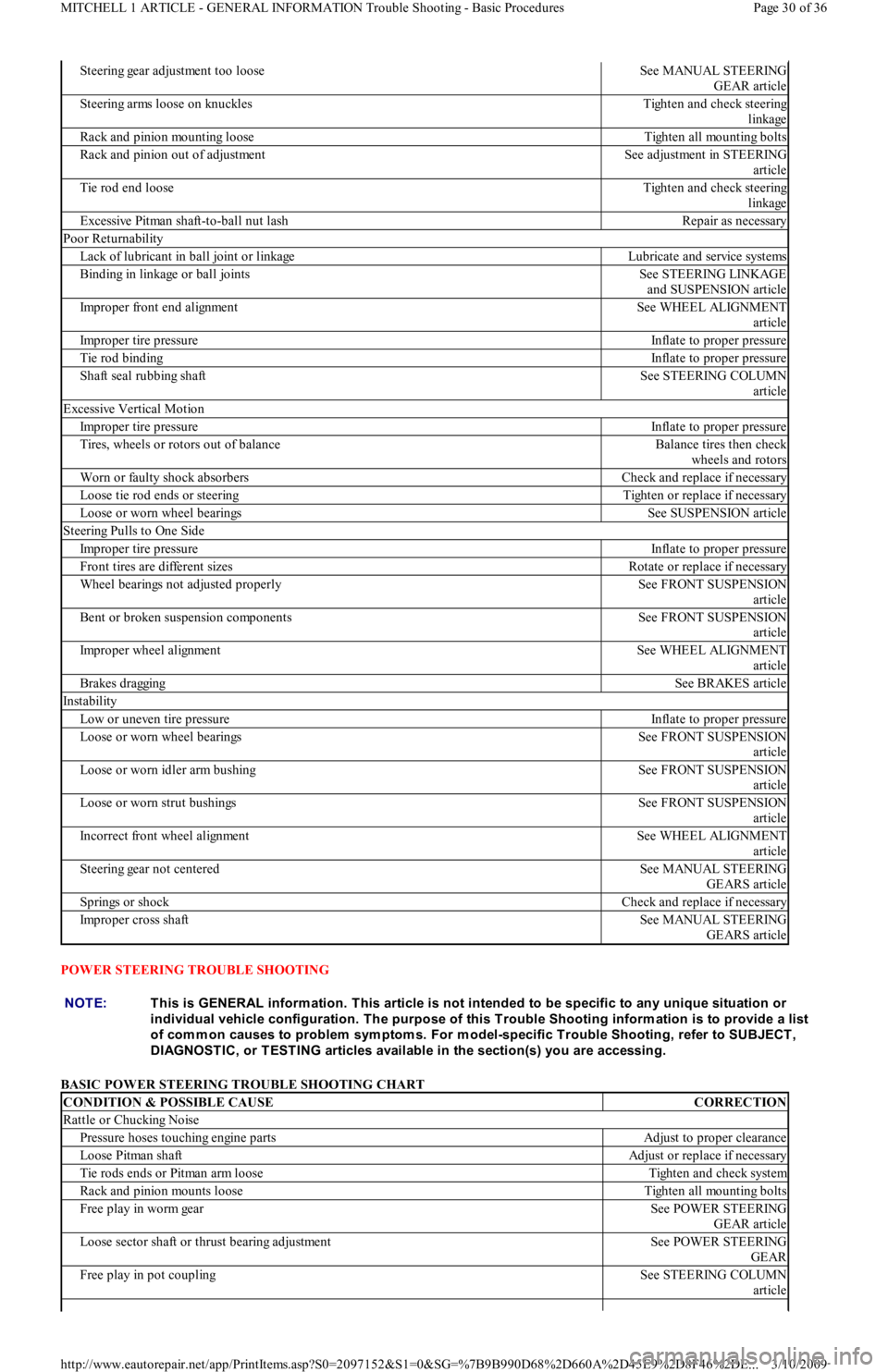
POWER STEERING TROUBLE SHOOTING
BASIC POWER STEERING TROUBLE SHOOTING CHART
Steering gear adjustment too looseSee MANUAL STEERING
GEAR article
Steering arms loose on knucklesTighten and check steering
linkage
Rack and pinion mounting looseTighten all mounting bolts
Rack and pinion out of adjustmentSee adjustment in STEERING
article
Tie rod end looseTighten and check steering
linkage
Excessive Pitman shaft-to-ball nut lashRepair as necessary
Poor Returnability
Lack of lubricant in ball joint or linkageLubricate and service systems
Binding in linkage or ball jointsSee STEERING LINKAGE
and SUSPENSION article
Improper front end alignmentSee WHEEL ALIGNMENT
article
Improper tire pressureInflate to proper pressure
Tie rod bindingInflate to proper pressure
Shaft seal rubbing shaftSee STEERING COLUMN
article
Excessive Vertical Motion
Improper tire pressureInflate to proper pressure
Tires, wheels or rotors out of balanceBalance tires then check
wheels and rotors
Worn or faulty shock absorbersCheck and replace if necessary
Loose tie rod ends or steeringTighten or replace if necessary
Loose or worn wheel bearingsSee SUSPENSION article
Steering Pulls to One Side
Improper tire pressureInflate to proper pressure
Front tires are different sizesRotate or replace if necessary
Wheel bearings not adjusted properlySee FRONT SUSPENSION
article
Bent or broken suspension componentsSee FRONT SUSPENSION
article
Improper wheel alignmentSee WHEEL ALIGNMENT
article
Brakes draggingSee BRAKES article
Instability
Low or uneven tire pressureInflate to proper pressure
Loose or worn wheel bearingsSee FRONT SUSPENSION
article
Loose or worn idler arm bushingSee FRONT SUSPENSION
article
Loose or worn strut bushingsSee FRONT SUSPENSION
article
Incorrect front wheel alignmentSee WHEEL ALIGNMENT
article
Steering gear not centeredSee MANUAL STEERING
GEARS article
Springs or shockCheck and replace if necessary
Improper cross shaftSee MANUAL STEERING
GEARS article
NOTE:This is GENERAL inform ation. This article is not intended to be specific to any unique situation or
individual vehicle configuration. T he purpose of this T rouble Shooting inform ation is to provide a list
of com m on causes to problem sym ptom s. For m odel-specific T rouble Shooting, refer to SUBJECT ,
DIAGNOST IC, or T EST ING articles available in the section(s) you are accessing.
CONDITION & POSSIBLE CAUSECORRECTION
Rattle or Chucking Noise
Pressure hoses touching engine partsAdjust to proper clearance
Loose Pitman shaftAdjust or replace if necessary
Tie rods ends or Pitman arm looseTighten and check system
Rack and pinion mounts looseTighten all mounting bolts
Free play in worm gearSee POWER STEERING
GEAR article
Loose sector shaft or thrust bearing adjustmentSee POWER STEERING
GEAR
Free play in pot couplingSee STEERING COLUMN
article
Page 30 of 36 MITCHELL 1 ARTICLE - GENERAL INFORMATION Trouble Shooting - Basic Procedures
3/10/2009 http://www.eautorepair.net/app/PrintItems.asp?S0=2097152&S1=0&SG=%7B9B990D68%2D660A%2D45E9%2D8F46%2DE
...
Page 245 of 454
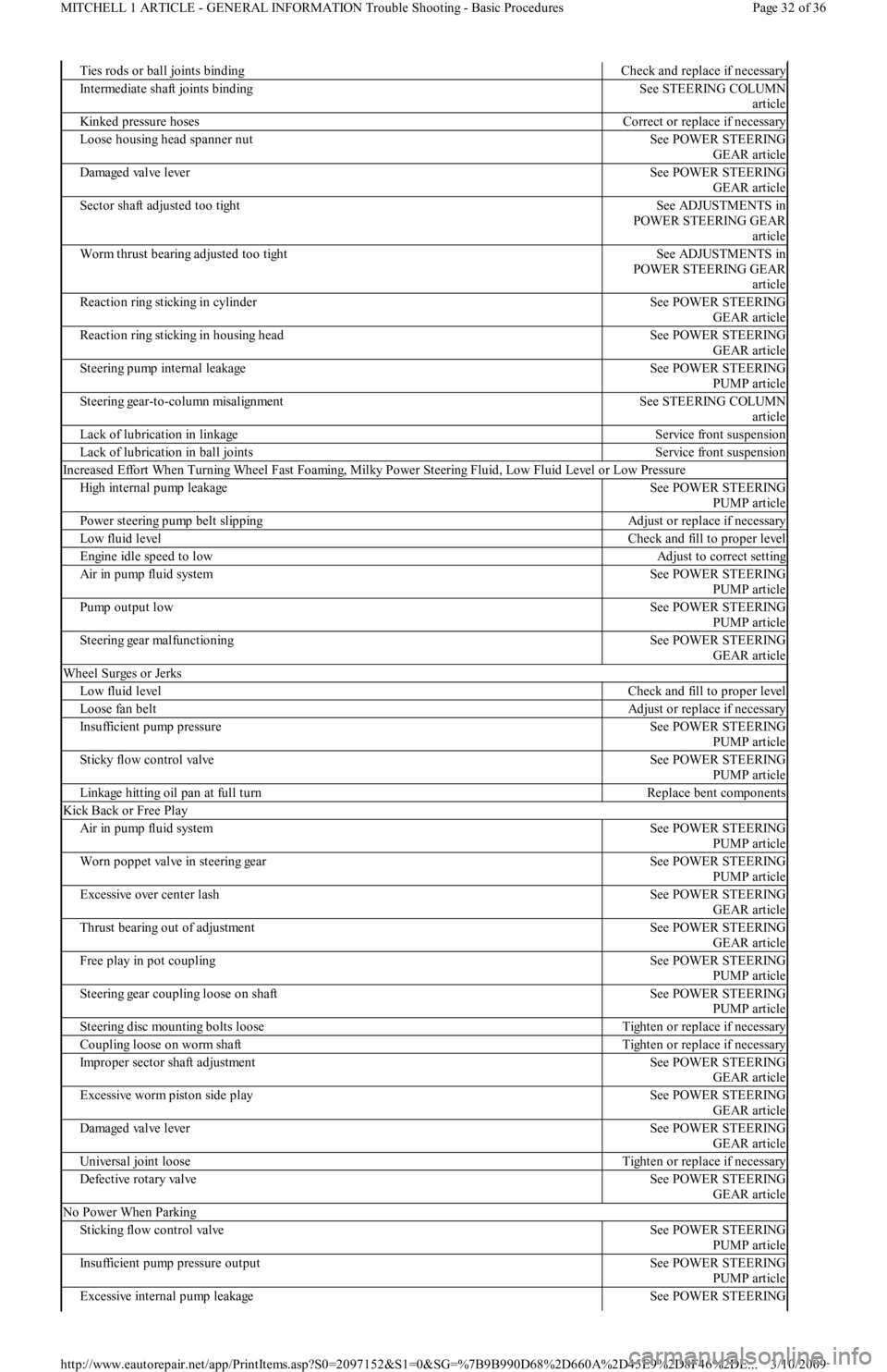
Ties rods or ball joints bindingCheck and replace if necessary
Intermediate shaft joints bindingSee STEERING COLUMN
article
Kinked pressure hosesCorrect or replace if necessary
Loose housing head spanner nutSee POWER STEERING
GEAR article
Damaged valve leverSee POWER STEERING
GEAR article
Sector shaft adjusted too tightSee ADJUSTMENTS in
POWER STEERING GEAR
article
Worm thrust bearing adjusted too tightSee ADJUSTMENTS in
POWER STEERING GEAR
article
Reaction ring sticking in cylinderSee POWER STEERING
GEAR article
Reaction ring sticking in housing headSee POWER STEERING
GEAR article
Steering pump internal leakageSee POWER STEERING
PUMP article
Steering gear-to-column misalignmentSee STEERING COLUMN
article
Lack of lubrication in linkageService front suspension
Lack of lubrication in ball jointsService front suspension
Increased Effort When Turning Wheel Fast Foaming, Milky Power Steering Fluid, Low Fluid Level or Low Pressure
High internal pump leakageSee POWER STEERING
PUMP article
Power steering pump belt slippingAdjust or replace if necessary
Low fluid levelCheck and fill to proper level
Engine idle speed to lowAdjust to correct setting
Air in pump fluid systemSee POWER STEERING
PUMP article
Pump output lowSee POWER STEERING
PUMP article
Steering gear malfunctioningSee POWER STEERING
GEAR article
Wheel Surges or Jerks
Low fluid levelCheck and fill to proper level
Loose fan beltAdjust or replace if necessary
Insufficient pump pressureSee POWER STEERING
PUMP article
Sticky flow control valveSee POWER STEERING
PUMP article
Linkage hitting oil pan at full turnReplace bent components
Kick Back or Free Play
Air in pump fluid systemSee POWER STEERING
PUMP article
Worn poppet valve in steering gearSee POWER STEERING
PUMP article
Excessive over center lashSee POWER STEERING
GEAR article
Thrust bearing out of adjustmentSee POWER STEERING
GEAR article
Free play in pot couplingSee POWER STEERING
PUMP article
Steering gear coupling loose on shaftSee POWER STEERING
PUMP article
Steering disc mounting bolts looseTighten or replace if necessary
Coupling loose on worm shaftTighten or replace if necessary
Improper sector shaft adjustmentSee POWER STEERING
GEAR article
Excessive worm piston side playSee POWER STEERING
GEAR article
Damaged valve leverSee POWER STEERING
GEAR article
Universal joint looseTighten or replace if necessary
Defective rotary valveSee POWER STEERING
GEAR article
No Power When Parking
Sticking flow control valveSee POWER STEERING
PUMP article
Insufficient pump pressure outputSee POWER STEERING
PUMP article
Excessive internal pump leakageSee POWER STEERING
Page 32 of 36 MITCHELL 1 ARTICLE - GENERAL INFORMATION Trouble Shooting - Basic Procedures
3/10/2009 http://www.eautorepair.net/app/PrintItems.asp?S0=2097152&S1=0&SG=%7B9B990D68%2D660A%2D45E9%2D8F46%2DE
...
Page 247 of 454
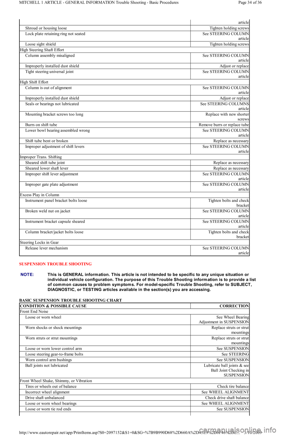
SUSPENSION TROUBLE SHOOTING
BASIC SUSPENSION TROUBLE SHOOTING CHART
article
Shroud or housing looseTighten holding screws
Lock plate retaining ring not seatedSee STEERING COLUMN
article
Loose sight shieldTighten holding screws
High Steering Shaft Effort
Co l u mn assemb l y misal ign edSee STEERING COLUMN
article
Improperly installed dust shieldAdjust or replace
Tight steering universal jointSee STEERING COLUMN
article
High Shift Effort
Column is out of alignmentSee STEERING COLUMN
article
Improperly installed dust shieldAdjust or replace
Seals or bearings not lubricatedSee STEERING COLUMNS
article
Mounting bracket screws too longReplace with new shorter
screws
Burrs on shift tubeRemove burrs or replace tube
Lower bowl bearing assembled wrongSee STEERING COLUMN
article
Shift tube bent or brokenReplace as necessary
Improper adjustment of shift leversSee STEERING COLUMN
article
Improper Trans. Shifting
Sheared shift tube jointReplace as necessary
Sheared lower shaft leverReplace as necessary
Improper shift lever adjustmentSee STEERING COLUMN
article
Improper gate plate adjustmentSee STEERING COLUMN
article
Excess Play in Column
Instrument panel bracket bolts looseTighten bolts and check
bracket
Broken weld nut on jacketSee STEERING COLUMN
article
Instrument bracket capsule shearedSee STEERING COLUMN
article
Column bracket/jacket bolts looseTighten bolts and check
bracket
Steering Locks in Gear
Release lever mechanismSee STEERING COLUMN
article
NOTE:This is GENERAL inform ation. This article is not intended to be specific to any unique situation or
individual vehicle configuration. T he purpose of this T rouble Shooting inform ation is to provide a list
of com m on causes to problem sym ptom s. For m odel-specific T rouble Shooting, refer to SUBJECT ,
DIAGNOST IC, or T EST ING articles available in the section(s) you are accessing.
CONDITION & POSSIBLE CAUSECORRECTION
Front End Noise
Loose or worn wheelSee Wheel Bearing
Adjustment in SUSPENSION
Worn shocks or shock mountingsReplace struts or strut
mo u n t in gs
Worn struts or strut mountingsReplace struts or strut
mo u n t in gs
Loose or worn lower control armSee SUSPENSION
Loose steering gear-to-frame boltsSee STEERING
Worn control arm bushingsSee SUSPENSION
Ball joints not lubricatedLubricate ball joints & see
Ball Joint Checking in
SUSPENSION
Front Wheel Shake, Shimmy, or Vibration
Tires or wheels out of balanceCheck tire balance
Incorrect wheel alignmentSee WHEEL ALIGNMENT
Drive shaft unbalancedCheck drive shaft balance
Loose or worn wheel bearingsSee WHEEL ALIGNMENT
Loose or worn tie rod endsSee SUSPENSION
Page 34 of 36 MITCHELL 1 ARTICLE - GENERAL INFORMATION Trouble Shooting - Basic Procedures
3/10/2009 http://www.eautorepair.net/app/PrintItems.asp?S0=2097152&S1=0&SG=%7B9B990D68%2D660A%2D45E9%2D8F46%2DE
...
Page 253 of 454
Back To Article
GENERAL INFORMATION
Drive Axle Noise Diagnosis
* PLEASE READ THIS FIRST *
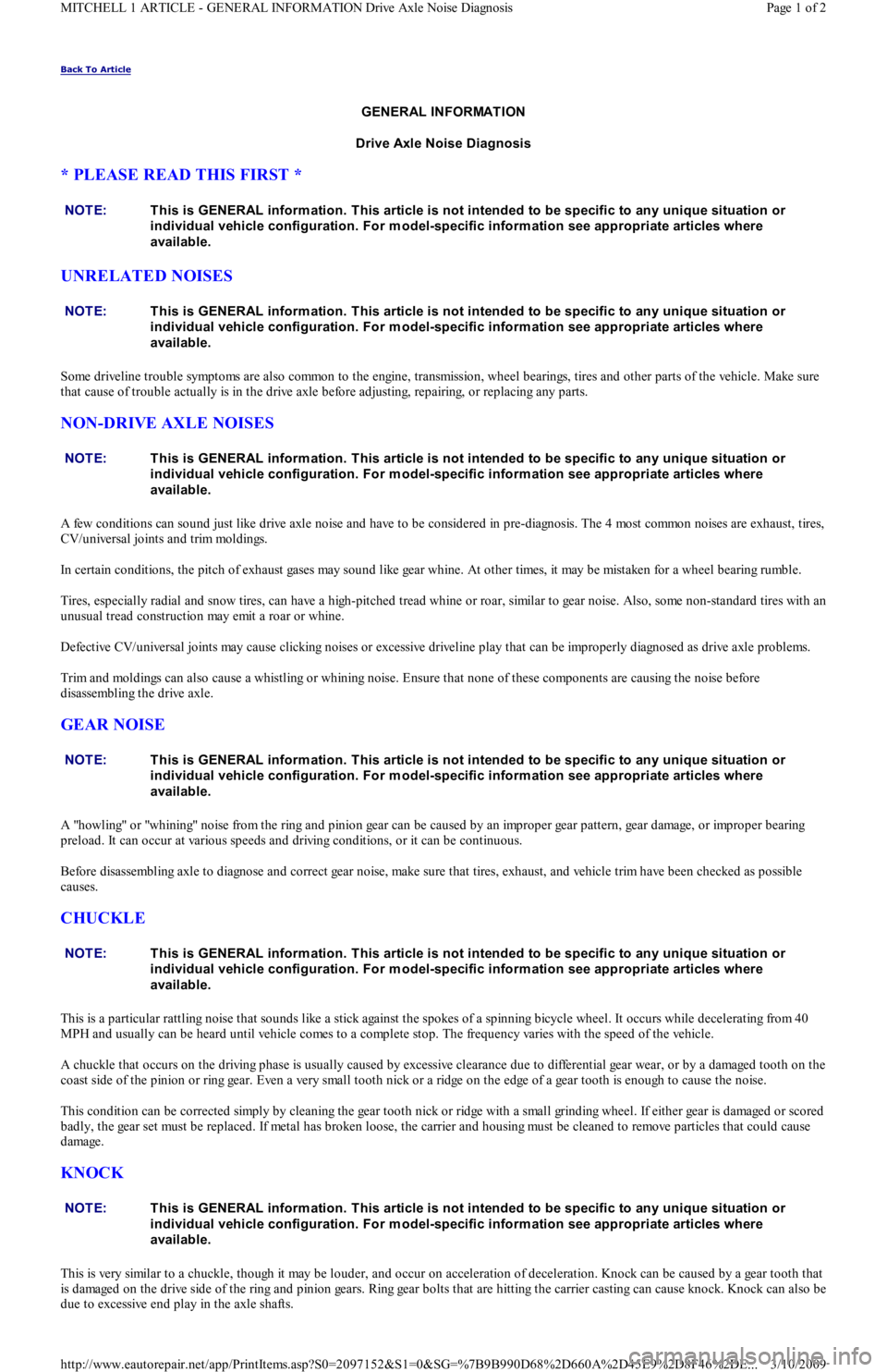
UNRELATED NOISES
Some driveline trouble symptoms are also common to the engine, transmission, wheel bearings, tires and other parts of the vehicle. Make sure
that cause of trouble actually is in the drive axle before adjusting, repairing, or replacing any parts.
NON-DRIVE AXLE NOISES
A few conditions can sound just like drive axle noise and have to be considered in pre-diagnosis. The 4 most common noises are exhaust, tires,
CV/universal joints and trim moldings.
In certain conditions, the pitch of exhaust gases may sound like gear whine. At other times, it may be mistaken for a wheel bearing rumble.
Tires, especially radial and snow tires, can have a high-pitched tread whine or roar, similar to gear noise. Also, some non-standard tires with an
unusual tread construction may emit a roar or whine.
Defective CV/universal joints may cause clicking noises or excessive driveline play that can be improperly diagnosed as drive axle problems.
Trim and moldings can also cause a whistling or whining noise. Ensure that none of these components are causing the noise before
disassembling the drive axle.
GEAR NOISE
A "howling" or "whining" noise from the ring and pinion gear can be caused by an improper gear pattern, gear damage, or improper bearing
preload. It can occur at various speeds and driving conditions, or it can be continuous.
Before disassembling axle to diagnose and correct gear noise, make sure that tires, exhaust, and vehicle trim have been checked as possible
causes.
CHUCKLE
This is a particular rattling noise that sounds like a stick against the spokes of a spinning bicycle wheel. It occurs while decelerating from 40
MPH and usually can be heard until vehicle comes to a complete stop. The frequency varies with the speed of the vehicle.
A chuckle that occurs on the driving phase is usually caused by excessive clearance due to differential gear wear, or by a damaged tooth on the
coast side of the pinion or ring gear. Even a very small tooth nick or a ridge on the edge of a gear tooth is enough to cause the noise.
This condition can be corrected simply by cleaning the gear tooth nick or ridge with a small grinding wheel. If either gear is damaged or scored
badly, the gear set must be replaced. If metal has broken loose, the carrier and housing must be cleaned to remove particles that could cause
damage.
KNOCK
This is very similar to a chuckle, though it may be louder, and occur on acceleration of deceleration. Knock can be caused by a gear tooth that
is damaged on the drive side of the ring and pinion gears. Ring gear bolts that are hitting the carrier casting can cause knock. Knock can also be
due to excessive end play in the axle shafts. NOTE:This is GENERAL inform ation. This article is not intended to be specific to any unique situation or
individual vehicle configuration. For m odel-specific inform ation see appropriate articles where
available.
NOTE:This is GENERAL inform ation. This article is not intended to be specific to any unique situation or
individual vehicle configuration. For m odel-specific inform ation see appropriate articles where
available.
NOTE:This is GENERAL inform ation. This article is not intended to be specific to any unique situation or
individual vehicle configuration. For m odel-specific inform ation see appropriate articles where
available.
NOTE:This is GENERAL inform ation. This article is not intended to be specific to any unique situation or
individual vehicle configuration. For m odel-specific inform ation see appropriate articles where
available.
NOTE:This is GENERAL inform ation. This article is not intended to be specific to any unique situation or
individual vehicle configuration. For m odel-specific inform ation see appropriate articles where
available.
NOTE:This is GENERAL inform ation. This article is not intended to be specific to any unique situation or
individual vehicle configuration. For m odel-specific inform ation see appropriate articles where
available.
Page 1 of 2 MITCHELL 1 ARTICLE - GENERAL INFORMATION Drive Axle Noise Diagnosis
3/10/2009 http://www.eautorepair.net/app/PrintItems.asp?S0=2097152&S1=0&SG=%7B9B990D68%2D660A%2D45E9%2D8F46%2DE
...
Page 303 of 454
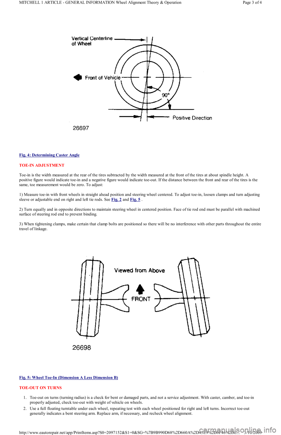
Fig. 4: Determining Caster Angle
TOE-IN ADJUSTMENT
Toe-in is the width measured at the rear of the tires subtracted by the width measured at the front of the tires at about spindle height. A
positive figure would indicate toe-in and a negative figure would indicate toe-out. If the distance between the front and rear of the tires is the
same, toe measurement would be zero. To adjust:
1) Measure toe-in with front wheels in straight ahead position and steering wheel centered. To adjust toe-in, loosen clamps and turn adjusting
sleeve or adjustable end on right and left tie rods. See Fig. 2
and Fig. 5 .
2) Turn equally and in opposite directions to maintain steering wheel in centered position. Face of tie rod end must be parallel with machined
surface of steering rod end to prevent binding.
3) When tightening clamps, make certain that clamp bolts are positioned so there will be no interference with other parts throughout the entire
travel of linkage.
Fig. 5: Wheel Toe
-In (Dimension A Less Dimension B)
TOE-OUT ON TURNS
1. Toe-out on turns (turning radius) is a check for bent or damaged parts, and not a service adjustment. With caster, camber, and toe-in
properly adjusted, check toe-out with weight of vehicle on wheels.
2. Use a full floating turntable under each wheel, repeating test with each wheel positioned for right and left turns. Incorrect toe-out
generally indicates a bent steering arm. Replace arm, if necessary, and recheck wheel alignment.
Page 3 of 4 MITCHELL 1 ARTICLE - GENERAL INFORMATION Wheel Alignment Theory & Operation
3/10/2009 http://www.eautorepair.net/app/PrintItems.asp?S0=2097152&S1=0&SG=%7B9B990D68%2D660A%2D45E9%2D8F46%2DE
...
Page 305 of 454
Back To Article
GENERAL INFORMATION
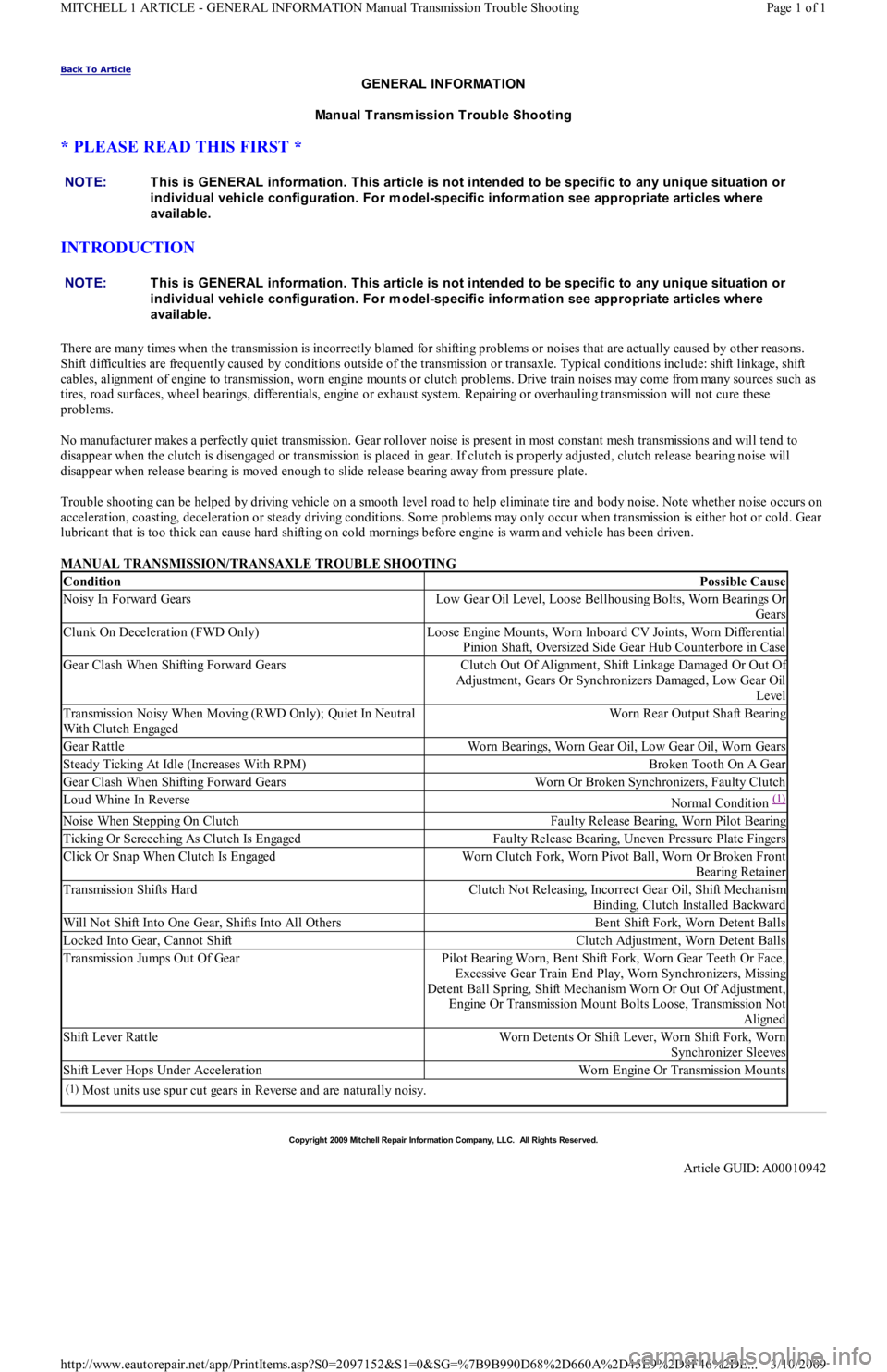
Manual Transmission Trouble Shooting
* PLEASE READ THIS FIRST *
INTRODUCTION
There are many times when the transmission is incorrectly blamed for shifting problems or noises that are actually caused by other reasons.
Shift difficulties are frequently caused by conditions outside of the transmission or transaxle. Typical conditions include: shift linkage, shift
cables, alignment of engine to transmission, worn engine mounts or clutch problems. Drive train noises may come from many sources such as
tires, road surfaces, wheel bearings, differentials, engine or exhaust system. Repairing or overhauling transmission will not cure these
problems.
No manufacturer makes a perfectly quiet transmission. Gear rollover noise is present in most constant mesh transmissions and will tend to
disappear when the clutch is disengaged or transmission is placed in gear. If clutch is properly adjusted, clutch release bearing noise will
disappear when release bearing is moved enough to slide release bearing away from pressure plate.
Trouble shooting can be helped by driving vehicle on a smooth level road to help eliminate tire and body noise. Note whether noise occurs on
acceleration, coasting, deceleration or steady driving conditions. Some problems may only occur when transmission is either hot or cold. Gear
lubricant that is too thick can cause hard shifting on cold mornings before engine is warm and vehicle has been driven.
MANUAL TRANSMISSION/TRANSAXLE TROUBLE SHOOTING NOTE:This is GENERAL inform ation. This article is not intended to be specific to any unique situation or
individual vehicle configuration. For m odel-specific inform ation see appropriate articles where
available.
NOTE:This is GENERAL inform ation. This article is not intended to be specific to any unique situation or
individual vehicle configuration. For m odel-specific inform ation see appropriate articles where
available.
ConditionPossible Cause
Noisy In Forward GearsLow Gear Oil Level, Loose Bellhousing Bolts, Worn Bearings Or
Gears
Clunk On Deceleration (FWD Only)Loose Engine Mounts, Worn Inboard CV Joints, Worn Differential
Pinion Shaft, Oversized Side Gear Hub Counterbore in Case
Gear Clash When Shifting Forward GearsClutch Out Of Alignment, Shift Linkage Damaged Or Out Of
Adjustment, Gears Or Synchronizers Damaged, Low Gear Oil
Level
Transmission Noisy When Moving (RWD Only); Quiet In Neutral
With Clutch EngagedWorn Rear Output Shaft Bearing
Gear RattleWorn Bearings, Worn Gear Oil, Low Gear Oil, Worn Gears
Steady Ticking At Idle (Increases With RPM)Broken Tooth On A Gear
Gear Clash When Shifting Forward GearsWorn Or Broken Synchronizers, Faulty Clutch
Loud Whine In ReverseNormal Condition (1)
Noise When Stepping On ClutchFaulty Release Bearing, Worn Pilot Bearing
Ticking Or Screeching As Clutch Is EngagedFaulty Release Bearing, Uneven Pressure Plate Fingers
Click Or Snap When Clutch Is EngagedWorn Clutch Fork, Worn Pivot Ball, Worn Or Broken Front
Bearing Retainer
Transmission Shifts HardClutch Not Releasing, Incorrect Gear Oil, Shift Mechanism
Binding, Clutch Installed Backward
Will Not Shift Into One Gear, Shifts Into All OthersBent Shift Fork, Worn Detent Balls
Locked Into Gear, Cannot ShiftClutch Adjustment, Worn Detent Balls
Transmission Jumps Out Of GearPilot Bearing Worn, Bent Shift Fork, Worn Gear Teeth Or Face,
Excessive Gear Train End Play, Worn Synchronizers, Missing
Detent Ball Spring, Shift Mechanism Worn Or Out Of Adjustment,
Engine Or Transmission Mount Bolts Loose, Transmission Not
Aligned
Shift Lever RattleWorn Detents Or Shift Lever, Worn Shift Fork, Worn
Synchronizer Sleeves
Shift Lever Hops Under AccelerationWorn Engine Or Transmission Mounts
(1)Most units use spur cut gears in Reverse and are naturally noisy.
Copyr ight 2009 Mitchell Repair Information Company, LLC. All Rights Reserved.
Article GUID: A00010942
Page 1 of 1 MITCHELL 1 ARTICLE - GENERAL INFORMATION Manual Transmission Trouble Shooting
3/10/2009 http://www.eautorepair.net/app/PrintItems.asp?S0=2097152&S1=0&SG=%7B9B990D68%2D660A%2D45E9%2D8F46%2DE
...
Page 346 of 454
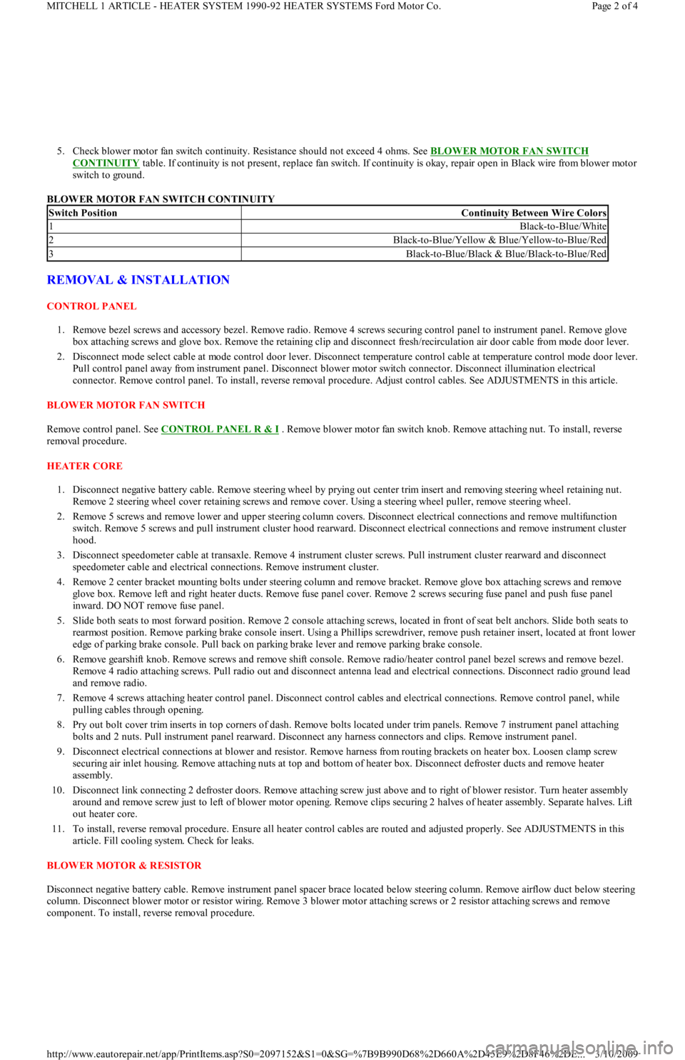
5. Check blower motor fan switch continuity. Resistance should not exceed 4 ohms. See BLOWER MOTOR FAN SWITCH
CONTINUITY table. If continuity is not present, replace fan switch. If continuity is okay, repair open in Black wire from blower motor
switch to ground.
BLOWER MOTOR FAN SWITCH CONTINUITY
REMOVAL & INSTALLATION
CONTROL PANEL
1. Remove bezel screws and accessory bezel. Remove radio. Remove 4 screws securing control panel to instrument panel. Remove glove
box attaching screws and glove box. Remove the retaining clip and disconnect fresh/recirculation air door cable from mode door lever.
2. Disconnect mode select cable at mode control door lever. Disconnect temperature control cable at temperature control mode door lever.
Pull control panel away from instrument panel. Disconnect blower motor switch connector. Disconnect illumination electrical
connector. Remove control panel. To install, reverse removal procedure. Adjust control cables. See ADJUSTMENTS in this article.
BLOWER MOTOR FAN SWITCH
Remove control panel. See CONTROL PANEL R & I
. Remove blower motor fan switch knob. Remove attaching nut. To install, reverse
removal procedure.
HEATER CORE
1. Disconnect negative battery cable. Remove steering wheel by prying out center trim insert and removing steering wheel retaining nut.
Remove 2 steering wheel cover retaining screws and remove cover. Using a steering wheel puller, remove steering wheel.
2. Remove 5 screws and remove lower and upper steering column covers. Disconnect electrical connections and remove multifunction
switch. Remove 5 screws and pull instrument cluster hood rearward. Disconnect electrical connections and remove instrument cluster
hood.
3. Disconnect speedometer cable at transaxle. Remove 4 instrument cluster screws. Pull instrument cluster rearward and disconnect
speedometer cable and electrical connections. Remove instrument cluster.
4. Remove 2 center bracket mounting bolts under steering column and remove bracket. Remove glove box attaching screws and remove
glove box. Remove left and right heater ducts. Remove fuse panel cover. Remove 2 screws securing fuse panel and push fuse panel
inward. DO NOT remove fuse panel.
5. Slide both seats to most forward position. Remove 2 console attaching screws, located in front of seat belt anchors. Slide both seats to
rearmost position. Remove parking brake console insert. Using a Phillips screwdriver, remove push retainer insert, located at front lower
edge of parking brake console. Pull back on parking brake lever and remove parking brake console.
6. Remove gearshift knob. Remove screws and remove shift console. Remove radio/heater control panel bezel screws and remove bezel.
Remove 4 radio attaching screws. Pull radio out and disconnect antenna lead and electrical connections. Disconnect radio ground lead
and remove radio.
7. Remove 4 screws attaching heater control panel. Disconnect control cables and electrical connections. Remove control panel, while
pulling cables through opening.
8. Pry out bolt cover trim inserts in top corners of dash. Remove bolts located under trim panels. Remove 7 instrument panel attaching
bolts and 2 nuts. Pull instrument panel rearward. Disconnect any harness connectors and clips. Remove instrument panel.
9. Disconnect electrical connections at blower and resistor. Remove harness from routing brackets on heater box. Loosen clamp screw
securing air inlet housing. Remove attaching nuts at top and bottom of heater box. Disconnect defroster ducts and remove heater
assembly.
10. Disconnect link connecting 2 defroster doors. Remove attaching screw just above and to right of blower resistor. Turn heater assembly
around and remove screw just to left of blower motor opening. Remove clips securing 2 halves of heater assembly. Separate halves. Lift
out heater core.
11. To install, reverse removal procedure. Ensure all heater control cables are routed and adjusted properly. See ADJUSTMENTS in this
article. Fill cooling system. Check for leaks.
BLOWER MOTOR & RESISTOR
Disconnect negative battery cable. Remove instrument panel spacer brace located below steering column. Remove airflow duct below steering
column. Disconnect blower motor or resistor wiring. Remove 3 blower motor attaching screws or 2 resistor attaching screws and remove
component. To install, reverse removal procedure.
Switch PositionContinuity Between Wire Colors
1Black-to-Blue/White
2Black-to-Blue/Yellow & Blue/Yellow-to-Blue/Red
3Black-to-Blue/Black & Blue/Black-to-Blue/Red
Page 2 of 4 MITCHELL 1 ARTICLE - HEATER SYSTEM 1990-92 HEATER SYSTEMS Ford Motor Co.
3/10/2009 http://www.eautorepair.net/app/PrintItems.asp?S0=2097152&S1=0&SG=%7B9B990D68%2D660A%2D45E9%2D8F46%2DE
...