wheel bolts FORD FESTIVA 1991 User Guide
[x] Cancel search | Manufacturer: FORD, Model Year: 1991, Model line: FESTIVA, Model: FORD FESTIVA 1991Pages: 454, PDF Size: 9.53 MB
Page 102 of 454
levels to proper level.
Removal (1.6L & 1.6L Turbo)
1. Relieve fuel pressure and discharge air conditioning system (if equipped). See FUEL PRESSURE RELEASE under REMOVAL &
INSTALLATION. Disconnect and remove battery, battery tray and battery tray support bracket.
2. Release wiring harness retaining straps from battery support tray. Disconnect windshield washer supply hose between fluid reservoir and
hood. Mark hinge locations and remove hood.
3. Disconnect intake air tube and wiring to ignition coil and vane airflow meter. Remove air cleaner/vane airflow meter assembly. Remove
air cleaner assembly support brackets. Disconnect intercooler hoses from turbocharger (if equipped).
4. Drain engine coolant and remove radiator. Disconnect accelerator cable, and remove retaining bracket from cam cover. Position cable to
one side.
5. Disconnect and plug fuel lines at fuel filter and pressure regulator. Disconnect power brake booster manifold vacuum hose from
manifold. Disconnect heater hoses at heater core tubes. Label and remove vacuum hoses located at throttle body.
6. For manual transaxle turbocharged vehicles, disconnect clutch cable and remove support bracket and cable from transmission. On non-
turbo vehicles, disconnect clutch slave hydraulic line. For automatic transaxle, remove transaxle cooler lines.
7. Disconnect starter wiring at starter. Remove harness from locating strap on bracket. Disconnect alternator wiring. Disconnect wiring
from engine coolant sensors located on rear of engine block. Remove ground connection at bracket on thermostat cover. Disconnect O2
sensor wire, main wiring harness connector, TPS connector (turbocharged only), knock sensor connector, distributor wiring and
transaxle wiring. Disconnect ground wire and strap at front of engine, and reinstall lifting eye.
8. Remove engine oil dipstick and retaining clip. Remove power steering pump from mounting bracket. Remove power steering pump
mounting bracket. With hoses attached, position pump aside. Remove upper air conditioning compressor retaining bolts (if equipped).
9. Raise vehicle on hoist. Drain engine oil and cooling system. On vehicles with air conditioning, remove lower air conditioning
compressor mounting bolts, and position compressor out of way.
10. Remove front wheels and tires. Remove front ball joints-to-ste e r in g kn u c kl e s r e t a in in g b o l t s. R e mo ve sp l a sh gu a r d s. Dr a in t ransmission
oil and remove half shafts from differential. Remove front exhaust pipe bracket located on lower side of engine. Disconnect front
exhaust pipe from exhaust manifold, or turbocharger (if equipped).
11. Remove frame support bar-to-engine support bolt. Loosen right control arm bolt and, pivot support bar downward. Disengage rubber
exhaust hangers located directly behind catalytic converter. Allow exhaust system to hang down 6 inches, and support system with
mechanic's wire. Unbolt shift linkage and stabilizer bar at transaxle. Remove nuts from front and rear engine mounts, and lower vehicle.
12. Attach chains onto lift eyes at ends of cylinder head, and support engine with hoist. Remove RH engine mount through bolt. Raise
engine off mounts and slightly pivot engine/transaxle assembly. Disconnect oil pressure sensor and route starter/alternator wiring
harness from engine. Carefully lift engine/transaxle assembly, turn assembly while raising to clear brake master cylinder, shift linkage
universal joint, radiator support and air conditioning lines (if equipped).
13. Remove intake manifold support bracket. Remove gusset plate(s) (if equipped). Remove starter. Remove transaxle-to-engine retaining
bolts. Identify bolts to ensure correct installation. Separate transaxle from engine. On manual transaxle, remove pressure plate, clutch
disc and flywheel. On automatic transaxle, remove flexplate.
Installation (1.6L & 1.6L Turbo)
1. Install transaxle to engine in reverse order of removal. Attach hoist to engine/transaxle assembly and position assembly in vehicle.
Before engine contacts mounts, route starter, alternator and oil pressure sensor wiring, and connect oil pressure sensor. Lower engine
until front mount seats on crossmember. Install through bolt on RH engine mount. DO NOT tighten bolt.
2. Remove hoist. Raise vehicle and support with jackstands. Align rear engine mount to crossmember, and install retaining nuts to front
and rear engine mounts. Tighten nuts to specification. See TORQUE SPECIFICATIONS
table at end of article.
3. On manual transaxles, connect shift coupling and stabilizer. Tighten to specification. On automatic transaxles, connect shift linkage and
oil cooler lines. Tighten linkage retaining bolt, shift cable pivot and oil cooler hose clamps to specification. Connect front exhaust pipe
to manifold (or turbocharger). Install exhaust pipe to support bracket. Tighten bolts to specification. Tighten manifold (or turbocharger)
to specification. Attach rubber exhaust hangers. Position cross brace. Tighten retaining nut and bolt and right control arm front bolt.
4. Install drive axles. Install ball joint retaining bolts and tighten to specification. Mount A/C Compressor to engine (if equipped). Tighten
lower retaining bolts to specification. Install splash guards. Install tire and wheel assemblies. Tighten retaining nuts to specification.
5. Lower vehicle. Install upper A/C compressor retaining bolts (if equipped). Tighten bolts to specification. Tighten RH engine mo u n t
through bolt to specification. Connect alternator wiring.
6. Position power steering pump bracket on stud. Lower pump into engine compartment. Install power steering pump bracket retaining
bolts and nut. Tighten to specification. Install power steering pump and belt. Tighten adjustment nut and pivot bolt to specification.
7. Install engine oil dipstick and retaining clip. Install ground strap and ground wire to cylinder head. Install clutch cable (if equipped).
Connect clutch hydraulic line if equipped with manual transaxle or naturally aspirated. Connect transmission electrical connectors.
Connect fuel lines to fuel filter and pressure regulator. Install intake air tube to throttle body.
8. Install intercooler hoses on turbocharged models. Install air cleaner assembly brackets. Install air cleaner assembly with airflow meter
attached. Install intake air tube. Install coil and airflow meter connectors. Connect coolant crankcase and air bypass hoses. Install
vacuum hoses as noted in disassembly.
9. Connect accelerator cable. Install retaining bracket. Install power brake booster hose. Remove speedometer cable from transaxle. Fill
transaxle to specification. See CAPACITIES in SERVICE & ADJUSTMENT SPECIFICATIONS article. Install speedometer cable.
Connect speedometer cable connector. Fill engine oil to capacity.
10. Install radiator/fan assembly. Tighten bracket retaining bolts to specification. Connect coolant hoses and fan electrical connector. Fill
coolant to specification.
11. Install hood and connect washer hose. Install battery tray support, battery tray, battery and battery hold-down. Connect battery
terminal. Evacuate and charge air conditioning system (if equipped). Road test vehicle and inspect for leaks.
INTAKE MANIFOLD
Removal (1.3L)
CAUT ION: DO NOT allow com pressor to hang by hoses. T ie up com pressor with m echanic's wire.
Page 2 of 19 MITCHELL 1 ARTICLE - ENGINE OVERHAUL 1991-92 FORD MOTOR CO. ENGINES 1.3L & 1.6L 4-Cylinder
3/10/2009 http://www.eautorepair.net/app/PrintItems.asp?S0=2097152&S1=0&SG=%7B959286D2%2D3A85%2D4BFC%2D9C5C%2D
...
Page 106 of 454
article. Install timing belt and covers. Install cam cover. On non-turbo engines, connect front exhaust pipe to exhaust manifold. Tighten
nuts to specification.
4. On turbocharged engines, install exhaust manifold and turbocharger assembly. Install ground wire and strap to cylinder head with
retaining bolts. Connect intercooler tubes (if equipped). Connect O2 sensor connector, and install ground wires to bracket on cylinder
head with retaining screw. Connect main engine harness connector. Connect fuel lines to fuel filter and pressure regulator. Install
throttle cable and retaining brackets.
5. Install coolant hoses and vacuum lines to intake manifold and throttle body. Install coolant hose to thermostat cover. Install intake air
tube to air cleaner. Install spark plug wires and retainers. Install intake air tube to throttle body, and connect by-pass hoses. Fill cooling
system. Connect negative battery terminal. Start engine, check for leaks and system operation.
TIMING BELT COVER
Removal & Installation (1.3L)
Remove accessory belts. Remove water pump pulley. Remove crankshaft damper. Remove bolts retaining upper and lower cover halves to
engine front. Remove both covers. To install, reverse removal procedure.
Removal & Installation (1.6L)
Raise vehicle on hoist. Remove RF tire and wheel assembly. Remove RF splash guard. Lower vehicle. Remove spark plugs and set camsh aft
timing to TDC No. 1 cylinder. Remove oil dipstick. Remove water pump pulley. Remove crankshaft pulley, damper and baffle plate. Remove
upper timing belt cover. Remove center and lower timing belt covers. To install, reverse removal procedure.
TIMING BELT
Removal (1.3L)
Remove accessory belts, water pump pulley, crankshaft damper and upper and lower timing belt covers. Mark timing belt direction of rotation
for installation reference. Remove timing belt tensioner pulley bolt. Remove tensioner pulley, spring and spring cover. Remove timing belt.
Installation (1.3L)
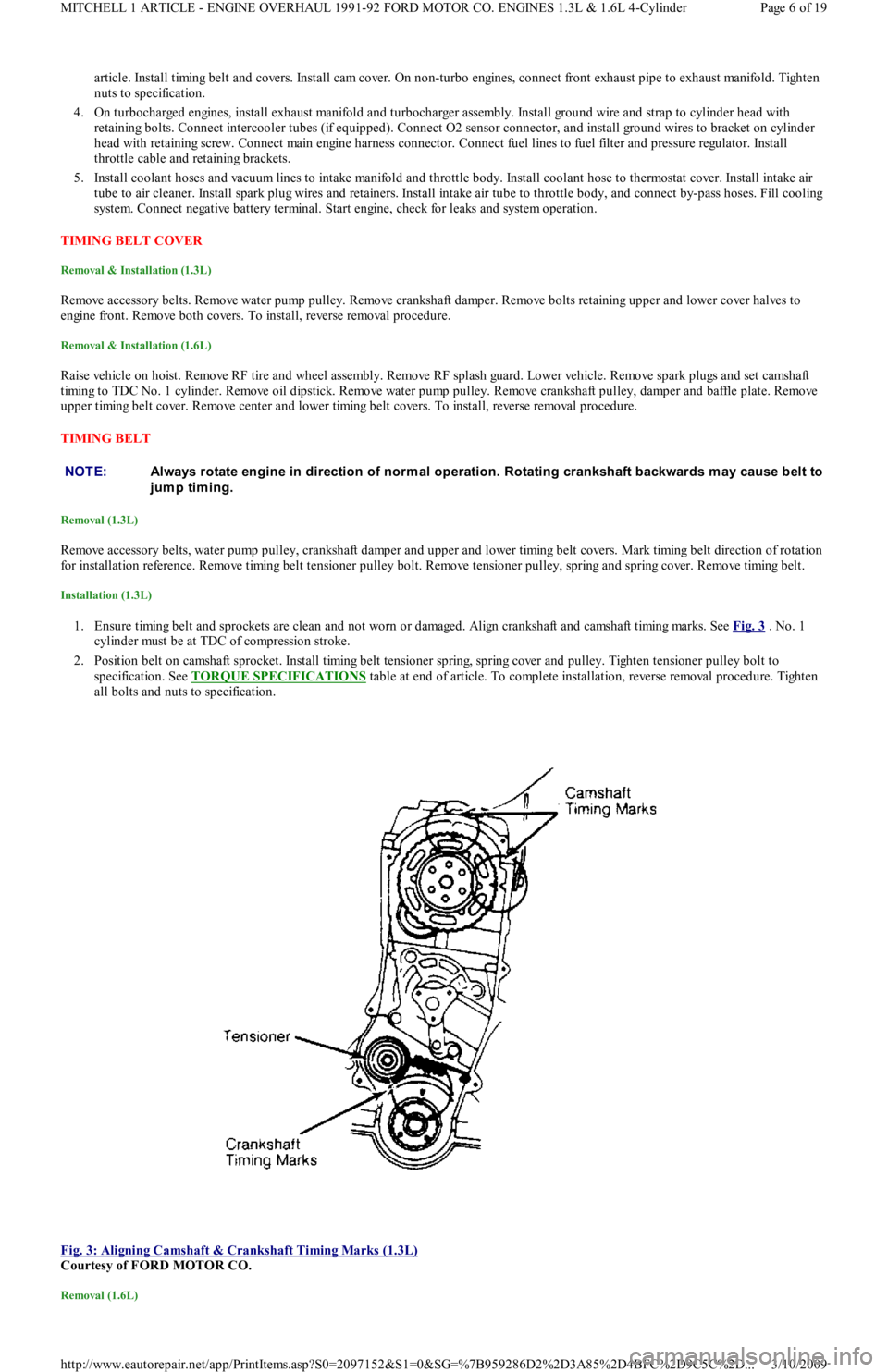
1. Ensure timing belt and sprockets are clean and not worn or damaged. Align crankshaft and camshaft timing marks. See Fig. 3 . No. 1
cylinder must be at TDC of compression stroke.
2. Position belt on camshaft sprocket. Install timing belt tensioner spring, spring cover and pulley. Tighten tensioner pulley bolt to
specification. See TORQUE SPECIFICATIONS
table at end of article. To complete installation, reverse removal procedure. Tighten
all bolts and nuts to specification.
Fig. 3: Aligning Camshaft & Crankshaft Timing Marks (1.3L)
Courtesy of FORD MOTOR CO.
Removal (1.6L)
NOTE:Always rotate engine in direction of norm al operation. Rotating crankshaft backwards m ay cause belt to
jump timing.
Page 6 of 19 MITCHELL 1 ARTICLE - ENGINE OVERHAUL 1991-92 FORD MOTOR CO. ENGINES 1.3L & 1.6L 4-Cylinder
3/10/2009 http://www.eautorepair.net/app/PrintItems.asp?S0=2097152&S1=0&SG=%7B959286D2%2D3A85%2D4BFC%2D9C5C%2D
...
Page 107 of 454
Remove timing belt covers, See TIMING BELT COVER procedure to remove timing belt from this engine.
Installation (1.6L)
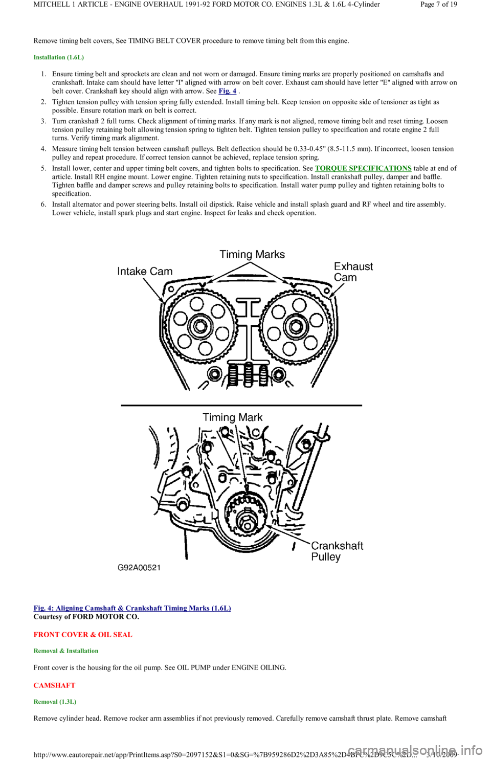
1. Ensure timing belt and sprockets are clean and not worn or damaged. Ensure timing marks are properly positioned on camshafts and
crankshaft. Intake cam should have letter "I" aligned with arrow on belt cover. Exhaust cam should have letter "E" aligned with arrow on
belt cover. Crankshaft key should align with arrow. See Fig. 4
.
2. Tighten tension pulley with tension spring fully extended. Install timing belt. Keep tension on opposite side of tensioner as tight as
possible. Ensure rotation mark on belt is correct.
3. Turn crankshaft 2 full turns. Check alignment of timing marks. If any mark is not aligned, remove timing belt and reset timing. Lo o se n
tension pulley retaining bolt allowing tension spring to tighten belt. Tighten tension pulley to specification and rotate engine 2 full
turns. Verify timing mark alignment.
4. Measure timing belt tension between camshaft pulleys. Belt deflection should be 0.33-0.45" (8.5-11.5 mm). If incorrect, loosen tension
pulley and repeat procedure. If correct tension cannot be achieved, replace tension spring.
5. Install lower, center and upper timing belt covers, and tighten bolts to specification. See TORQUE SPECIFICATIONS
table at end of
article. Install RH engine mount. Lower engine. Tighten retaining nuts to specification. Install crankshaft pulley, damper and baffle.
Tighten baffle and damper screws and pulley retaining bolts to specification. Install water pump pulley and tighten retaining bolts to
specification.
6. Install alternator and power steering belts. Install oil dipstick. Raise vehicle and install splash guard and RF wheel and tire assembly.
Lower vehicle, install spark plugs and start engine. Inspect for leaks and check operation.
Fig. 4: Aligning Camshaft & Crankshaft Timing Marks (1.6L)
Courtesy of FORD MOTOR CO.
FRONT COVER & OIL SEAL
Removal & Installation
Front cover is the housing for the oil pump. See OIL PUMP under ENGINE OILING.
CAMSHAFT
Removal (1.3L)
Remove cylinder head. Remove rocker arm assemblies if not previously removed. Carefully remove camshaft thrust plate. Remove camsh aft
Page 7 of 19 MITCHELL 1 ARTICLE - ENGINE OVERHAUL 1991-92 FORD MOTOR CO. ENGINES 1.3L & 1.6L 4-Cylinder
3/10/2009 http://www.eautorepair.net/app/PrintItems.asp?S0=2097152&S1=0&SG=%7B959286D2%2D3A85%2D4BFC%2D9C5C%2D
...
Page 111 of 454
bearing oil seal. To complete installation, reverse removal procedure.
WATER PUMP
Removal & Installation (1.3L)
Remove timing belt. Drain cooling system. Remove lower radiator hose and heater return hose from water pump. Remove water pump
retaining bolts and water pump. Clean gasket mounting surface and replace gasket. To install, reverse removal procedure.
Removal (1.6L)
1. Remove timing belt. See TIMING BELT . Drain cooling system. Remove timing belt tensioner and idler pulleys. Remove oil dipstick
bracket retaining bolt.
2. Remove power steering pump from retaining bracket, leaving hoses attached. Remove power steering bracket and position power
steering pump to one side. Remove water pump outlet. Remove water pump retaining bolts and water pump.
Installation (1.6L)
1. Clean all gasket surfaces. Transfer rubber belt cover seal to new water pump (if required). Position water pump with new gasket and
install retaining bolts. Install pump outlet with new gasket and "O" ring. See TORQUE SPECIFICATIONS
table at end of article.
2. Install oil dipstick retaining bolt. Install timing belt tensioner and idler pulleys. Install power steering pump bracket. Install power
steering pump. Tighten all bolts and nuts to specification. See TORQUE SPECIFICATIONS
table at end of article.
3. Install timing belt. Fill cooling system. Start engine and check for leaks and proper system function.
OIL PAN
Removal (1.3L)
Disconnect battery ground cable. Raise vehicle and drain engine oil. Remove flywheel housing dust cover. Remove oil pan retaining bolts,
nuts and stiffeners. Rotate crankshaft while removing oil pan. Remove baffle plate from oil pan. Clean gasket mating surfaces thoroughly.
Installation (1.3L)
Ensure gasket surfaces are clean. Apply oil resistant sealer to front and rear engine covers and across joint line of cylinder block.
Removal (1.6L)
1. Raise vehicle and drain engine oil. Remove frame brace retaining bolt. Loosen RH "A" arm front bolt, and pivot brace downward.
Disconnect front exhaust pipe from exhaust manifold (or turbocharger). Remove exhaust pipe bracket retaining bolts. Loosen rubber
exhaust hangers at catalytic converter.
2. Allow exhaust to hang supported by mechanic's wire. Disconnect turbocharger oil return hose (if equipped). Remove oil pan retaining
bolts. Carefully pry oil pan loose from cylinder block.
Installation (1.6L)
1. Clean pan and block gasket surfaces. Apply Gasket Sealant (E3AZ-19562-A) to new front and rear pan seals. Install seals to cylinder
block. Apply Gasket Sealant (E3AZ-19562-A) to oil pan gasket surface. See Fig. 8
. Install oil pan and tighten pan retaining bolts to
specification. See TORQUE SPECIFICATIONS
table at end of article.
2. Connect turbocharger oil return hose (if equipped). Install rubber exhaust hanger to brackets. Install new gasket and connect fro n t
exhaust pipe to exhaust manifold (or turbocharger). Install front exhaust pipe bracket. Tighten nuts and bolts to specification.
3. Pivot frame brace into position. Tighten retaining bolt to crossmember and RH "A" arm front retaining bolt to specification. Lower
vehicle, fill with oil and start engine. Check for oil leaks and system operation. NOTE:Raise engine slightly with floor jack, if required, to gain clearance for water pum p rem oval.
CAUT ION: DO NOT force a pry tool between cylinder block and oil pan.
Page 11 of 19 MITCHELL 1 ARTICLE - ENGINE OVERHAUL 1991-92 FORD MOTOR CO. ENGINES 1.3L & 1.6L 4-Cylinder
3/10/2009 http://www.eautorepair.net/app/PrintItems.asp?S0=2097152&S1=0&SG=%7B959286D2%2D3A85%2D4BFC%2D9C5C%2D
...
Page 115 of 454
Installation
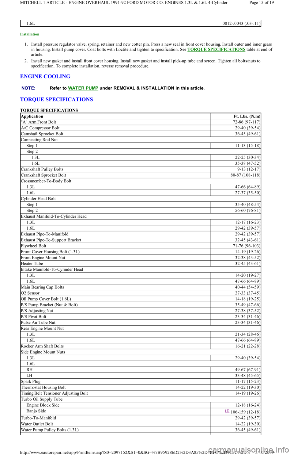
1. Install pressure regulator valve, spring, retainer and new cotter pin. Press a new seal in front cover housing. Install outer and inner gears
in housing. Install pump cover. Coat bolts with Loctite and tighten to specification. See TORQUE SPECIFICATIONS
table at end of
article.
2. Install new gasket and install front cover housing. Install new gasket and install pick-up tube and screen. Tighten all bolts/nuts to
specification. To complete installation, reverse removal procedure.
ENGINE COOLING
TORQUE SPECIFICATIONS
TORQUE SPECIFICATIONS
1.6L.0012-.0043 (.03-.11)
NOTE:Refer to WAT ER PUMP
under REMOVAL & INSTALLATION in this article.
ApplicationFt. Lbs. (N.m)
"A" Arm Front Bolt72-86 (97-117)
A/C Compressor Bolt29-40 (39-54)
Camshaft Sprocket Bolt36-45 (49-61)
Connecting Rod Nut
Step 111-13 (15-18)
Step 2
1.3L22-25 (30-34)
1.6L35-38 (47-52)
Crankshaft Pulley Bolts9-13 (12-17)
Crankshaft Sprocket Bolt80-87 (108-118)
Crossmember-To-Body Bolt
1.3L47-66 (64-89)
1.6L27-37 (35-50)
Cylinder Head Bolt
Step 135-40 (48-54)
Step 256-60 (76-81)
Exhaust Manifold-To-Cylinder Head
1.3L12-17 (16-23)
1.6L29-42 (39-57)
Exhaust Pipe-To-Manifold29-42 (39-57)
Exhaust Pipe-To-Support Bracket32-45 (43-61)
Flywheel Bolt71-76 (96-103)
Front Cover Housing Bolt (1.3L)14-19 (19-26)
Front Engine Mount Nut32-38 (43-52)
Heater Tube32-45 (43-61)
Intake Manifold-To-Cylinder Head
1.3L14-20 (19-27)
1.6L47-66 (64-89)
Main Bearing Cap Bolts40-44 (54-59)
O2 Sensor27-33 (37-45)
Oil Pump Cover Bolt (1.6L)14-18 (19-25)
P/S Pump Bracket (Nut & Bolt)35-49 (47-66)
P/S Adjusting Nut27-38 (37-52)
P/S Pivot Bolt23-34 (31-46)
Pulse Air Tube Nut23-34 (31-46)
Rear Engine Mount Nut
1.3L21-34 (28-46)
1.6L47-66 (64-89)
Rocker Arm Shaft Bolts16-21 (22-28)
Side Engine Mount Nuts
1.3L29-40 (39-54)
1.6L
RH49-67 (67-91)
LH33-48 (45-65)
Spark Plug11-17 (15-23)
Thermostat Housing Bolt14-22 (19-30)
Timing Belt Tensioner Adjusting Bolt14-19 (19-26)
Turbo Oil Supply Tube
Engine Block Side12-18 (16-24)
Banjo Side(1) 106-159 (12-18)
Turbo-To-Manifold29-42 (39-57)
Water Outlet Bolt14-22 (19-30)
Water Pump Pulley Bolts (1.3L)36-45 (49-61)
Page 15 of 19 MITCHELL 1 ARTICLE - ENGINE OVERHAUL 1991-92 FORD MOTOR CO. ENGINES 1.3L & 1.6L 4-Cylinder
3/10/2009 http://www.eautorepair.net/app/PrintItems.asp?S0=2097152&S1=0&SG=%7B959286D2%2D3A85%2D4BFC%2D9C5C%2D
...
Page 116 of 454
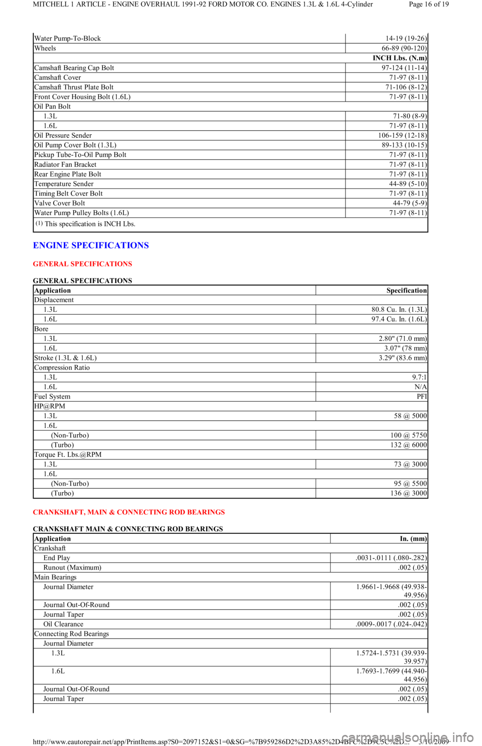
ENGINE SPECIFICATIONS
GENERAL SPECIFICATIONS
GENERAL SPECIFICATIONS
CRANKSHAFT, MAIN & CONNECTING ROD BEARINGS
CRANKSHAFT MAIN & CONNECTING ROD BEARINGS
Water Pump-To-Block14-19 (19-26)
Wheels66-89 (90-120)
INCH Lbs. (N.m)
Camshaft Bearing Cap Bolt97-124 (11-14)
Camshaft Cover71-97 (8-11)
Camshaft Thrust Plate Bolt71-106 (8-12)
Front Cover Housing Bolt (1.6L)71-97 (8-11)
Oil Pan Bolt
1.3L71-80 (8-9)
1.6L71-97 (8-11)
Oil Pressure Sender106-159 (12-18)
Oil Pump Cover Bolt (1.3L)89-133 (10-15)
Pickup Tube-To-Oil Pump Bolt71-97 (8-11)
Radiator Fan Bracket71-97 (8-11)
Rear Engine Plate Bolt71-97 (8-11)
Temperature Sender44-89 (5-10)
Timing Belt Cover Bolt71-97 (8-11)
Valve Cover Bolt44-79 (5-9)
Water Pump Pulley Bolts (1.6L)71-97 (8-11)
(1)This specification is INCH Lbs.
ApplicationSpecification
Displacement
1.3L80.8 Cu. In. (1.3L)
1.6L97.4 Cu. In. (1.6L)
Bore
1.3L2.80" (71.0 mm)
1.6L3.07" (78 mm)
Stroke (1.3L & 1.6L)3.29" (83.6 mm)
Compression Ratio
1.3L9.7:1
1.6LN/A
Fuel SystemPFI
HP@RPM
1.3L58 @ 5000
1.6L
(Non-Turbo)100 @ 5750
(Turbo)132 @ 6000
Torque Ft. Lbs.@RPM
1.3L73 @ 3000
1.6L
(Non-Turbo)95 @ 5500
(Turbo)136 @ 3000
ApplicationIn. (mm)
Crankshaft
End Play.0031-.0111 (.080-.282)
Runout (Maximum).002 (.05)
Main Bearings
Journal Diameter1.9661-1.9668 (49.938-
49.956)
Journal Out-Of-Round.002 (.05)
Journal Taper.002 (.05)
Oil Clearance.0009-.0017 (.024-.042)
Connecting Rod Bearings
Journal Diameter
1.3L1.5724-1.5731 (39.939-
39.957)
1.6L1.7693-1.7699 (44.940-
44.956)
Journal Out-Of-Round.002 (.05)
Journal Taper.002 (.05)
Page 16 of 19 MITCHELL 1 ARTICLE - ENGINE OVERHAUL 1991-92 FORD MOTOR CO. ENGINES 1.3L & 1.6L 4-Cylinder
3/10/2009 http://www.eautorepair.net/app/PrintItems.asp?S0=2097152&S1=0&SG=%7B959286D2%2D3A85%2D4BFC%2D9C5C%2D
...
Page 218 of 454
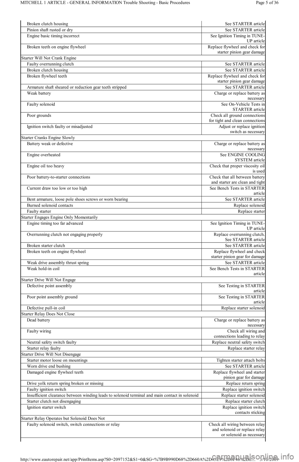
Broken clutch housingSee STARTER article
Pinion shaft rusted or drySee STARTER article
Engine basic timing incorrectSee Ignition Timing in TUNE-
UP article
Broken teeth on engine flywheelReplace flywheel and check for
starter pinion gear damage
Starter Will Not Crank Engine
Faulty overrunning clutchSee STARTER article
Broken clutch housingSee STARTER article
Broken flywheel teethReplace flywheel and check for
starter pinion gear damage
Armature shaft sheared or reduction gear teeth strippedSee STARTER article
Weak batteryCharge or replace battery as
necessary
Faulty solenoidSee On-Vehicle Tests in
STARTER article
Poor groundsCheck all ground connections
for tight and clean connections
Ignition switch faulty or misadjustedAdjust or replace ignition
switch as necessary
Starter Cranks Engine Slowly
Battery weak or defectiveCharge or replace battery as
necessary
Engine overheatedSee ENGINE COOLING
SYSTEM article
Engine oil too heavyCheck that proper viscosity oil
is used
Poor battery-to-starter connectionsCheck that all between battery
and starter are clean and tight
Current draw too low or too highSee Bench Tests in STARTER
article
Bent armature, loose pole shoes screws or worn bearingSee STARTER article
Burned solenoid contactsReplace solenoid
Faulty starterReplace starter
S t a r t e r E n ga ge s E n gin e On l y M o me n t a r il y
Engine timing too far advancedSee Ignition Timing in TUNE-
UP article
Overrunning clutch not engaging properlyReplace overrunning clutch.
See STARTER article
Broken starter clutchSee STARTER article
Broken teeth on engine flywheelReplace flywheel and check
starter pinion gear for damage
Weak drive assembly thrust springSee STARTER article
Weak hold-in coilSee Bench Tests in STARTER
article
Starter Drive Will Not Engage
Defective point assemblySee Testing in STARTER
article
Poor point assembly groundSee Testing in STARTER
article
Defective pull-in coilReplace starter solenoid
Starter Relay Does Not Close
Dead batteryCharge or replace battery as
necessary
Faulty wiringCheck all wiring and
connections leading to relay
Neutral safety switch faultyReplace neutral safety switch
Starter relay faultyReplace starter relay
Starter Drive Will Not Disengage
Starter motor loose on mountingsTighten starter attach bolts
Worn drive end bushingSee STARTER article
Damaged engine flywheel teethReplace flywheel and starter
pinion gear for damage
Drive yolk return spring broken or missingReplace return spring
Faulty ignition switchReplace ignition switch
Insufficient clearance between winding leads to solenoid terminal and main contact in solenoidReplace starter solenoid
Starter clutch not disengagingReplace starter clutch
Ignition starter switchReplace ignition switch
contacts sticking
Starter Relay Operates but Solenoid Does Not
Faulty solenoid switch, switch connections or relayCheck all wiring between relay
and solenoid or replace relay
or solenoid as necessary
Page 5 of 36 MITCHELL 1 ARTICLE - GENERAL INFORMATION Trouble Shooting - Basic Procedures
3/10/2009 http://www.eautorepair.net/app/PrintItems.asp?S0=2097152&S1=0&SG=%7B9B990D68%2D660A%2D45E9%2D8F46%2DE
...
Page 219 of 454
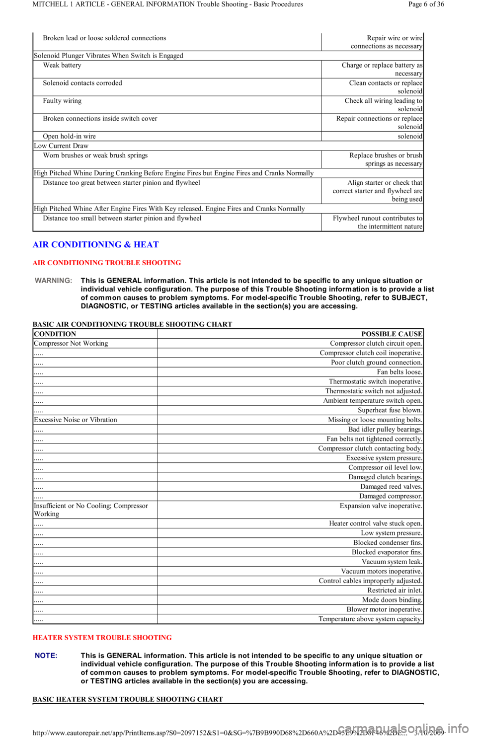
AIR CONDITIONING & HEAT
AIR CONDITIONING TROUBLE SHOOTING
BASIC AIR CONDITIONING TROUBLE SHOOTING CHART
HEATER SYSTEM TROUBLE SHOOTING
BASIC HEATER SYSTEM TROUBLE SHOOTING CHART
Broken lead or loose soldered connectionsRepair wire or wire
connections as necessary
Solenoid Plunger Vibrates When Switch is Engaged
Weak batteryCharge or replace battery as
necessary
Solenoid contacts corrodedClean contacts or replace
solenoid
Faulty wiringCheck all wiring leading to
solenoid
Broken connections inside switch coverRepair connections or replace
solenoid
Open hold-in wiresolenoid
Low Current Draw
Worn brushes or weak brush springsReplace brushes or brush
springs as necessary
High Pitched Whine During Cranking Before Engine Fires but Engine Fires and Cranks Normally
Distance too great between starter pinion and flywheelAlign starter or check that
correct starter and flywheel are
being used
High Pitched Whine After Engine Fires With Key released. Engine Fires and Cranks Normally
Distance too small between starter pinion and flywheelFlywheel runout contributes to
the intermittent nature
WARNING:This is GENERAL inform ation. This article is not intended to be specific to any unique situation or
individual vehicle configuration. T he purpose of this T rouble Shooting inform ation is to provide a list
of com m on causes to problem sym ptom s. For m odel-specific T rouble Shooting, refer to SUBJECT ,
DIAGNOST IC, or T EST ING articles available in the section(s) you are accessing.
CONDITIONPOSSIBLE CAUSE
Compressor Not WorkingCompressor clutch circuit open.
.....Compressor clutch coil inoperative.
.....Poor clutch ground connection.
.....Fan belts loose.
.....Thermostatic switch inoperative.
.....Thermostatic switch not adjusted.
.....Ambient temperature switch open.
.....Superheat fuse blown.
Excessive Noise or VibrationMissing or loose mounting bolts.
.....Bad idler pulley bearings.
.....Fan belts not tightened correctly.
.....Compressor clutch contacting body.
.....Excessive system pressure.
.....Compressor oil level low.
.....Damaged clutch bearings.
.....Damaged reed valves.
.....Damaged compressor.
In su fficien t o r No Co o l in g; Co mp resso r
WorkingExpansion valve inoperative.
.....Heater control valve stuck open.
.....Low system pressure.
.....Blocked condenser fins.
.....Blocked evaporator fins.
.....Vacuum system leak.
.....Vacuum motors inoperative.
.....Control cables improperly adjusted.
.....Restricted air inlet.
.....Mode doors binding.
.....Blower motor inoperative.
.....Temperature above system capacity.
NOTE:This is GENERAL inform ation. This article is not intended to be specific to any unique situation or
individual vehicle configuration. T he purpose of this T rouble Shooting inform ation is to provide a list
of com m on causes to problem sym ptom s. For m odel-specific T rouble Shooting, refer to DIAGNOST IC,
or T EST ING articles available in the section(s) you are accessing.
Page 6 of 36 MITCHELL 1 ARTICLE - GENERAL INFORMATION Trouble Shooting - Basic Procedures
3/10/2009 http://www.eautorepair.net/app/PrintItems.asp?S0=2097152&S1=0&SG=%7B9B990D68%2D660A%2D45E9%2D8F46%2DE
...
Page 224 of 454
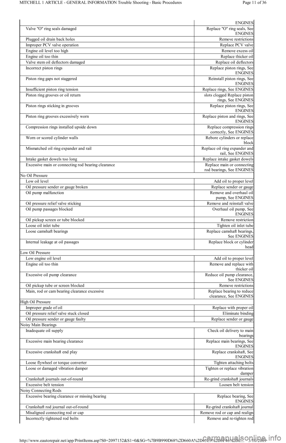
ENGINES
Valve "O" ring seals damagedReplace "O" ring seals, See
ENGINES
Plugged oil drain back holesRemove restrictions
Improper PCV valve operationReplace PCV valve
Engine oil level too highRemove excess oil
Engine oil too thinReplace thicker oil
Valve stem oil deflectors damagedReplace oil deflectors
Incorrect piston ringsReplace piston rings, See
ENGINES
Piston ring gaps not staggeredReinstall piston rings, See
ENGINES
Insufficient piston ring tensionReplace rings, See ENGINES
Piston ring grooves or oil returnslots clogged Replace piston
rings, See ENGINES
Piston rings sticking in groovesReplace piston rings, See
ENGINES
Piston ring grooves excessively wornReplace piston and rings, See
ENGINES
Compression rings installed upside downReplace compression rings
correctly, See ENGINES
Worn or scored cylinder wallsRebore cylinders or replace
block
Mismatched oil ring expander and railReplace oil ring expander and
rail, See ENGINES
Intake gasket dowels too longReplace intake gasket dowels
Excessive main or connecting rod bearing clearanceReplace main or connecting
rod bearings, See ENGINES
No Oil Pressure
Low oil levelAdd oil to proper level
Oil pressure sender or gauge brokenReplace sender or gauge
Oil pump malfunctionRemove and overhaul oil
pump, See ENGINES
Oil pressure relief valve stickingR e mo ve a n d r e in st a l l va l ve
Oil pump passages blockedOverhaul oil pump, See
ENGINES
Oil pickup screen or tube blockedRemove restriction
Loose oil inlet tubeTighten oil inlet tube
Loose camshaft bearingsReplace camshaft bearings,
See ENGINES
Internal leakage at oil passagesReplace block or cylinder
head
Low Oil Pressure
Low engine oil levelAdd oil to proper level
Engine oil too thinRemove and replace with
thicker oil
Excessive oil pump clearanceReduce oil pump clearance,
See ENGINES
Oil pickup tube or screen blockedRemove restrictions
Main, rod or cam bearing clearance excessiveReplace bearing to reduce
clearance, See ENGINES
High Oil Pressure
Improper grade of oilReplace with proper oil
Oil pressure relief valve stuck closedEliminate binding
Oil pressure sender or gauge faultyReplace sender or gauge
Noisy Main Bearings
Inadequate oil supplyCheck oil delivery to main
bearings
Excessive main bearing clearanceReplace main bearings, See
ENGINES
Excessive crankshaft end playReplace crankshaft, See
ENGINES
Loose flywheel or torque converterTighten attaching bolts
Loose or damaged vibration damperTighten or replace vibration
damper
Crankshaft journals out-of-roundRe-grind crankshaft journals
Excessive belt tensionLoosen belt tension
Noisy Connecting Rods
Excessive bearing clearance or missing bearingReplace bearing, See
ENGINES
Crankshaft rod journal out-of-roundRe-grind crankshaft journal
Misaligned connecting rod or capRemove rod or cap and realign
Incorrectly tightened rod boltsRemove and re-tighten rod
Page 11 of 36 MITCHELL 1 ARTICLE - GENERAL INFORMATION Trouble Shooting - Basic Procedures
3/10/2009 http://www.eautorepair.net/app/PrintItems.asp?S0=2097152&S1=0&SG=%7B9B990D68%2D660A%2D45E9%2D8F46%2DE
...
Page 233 of 454
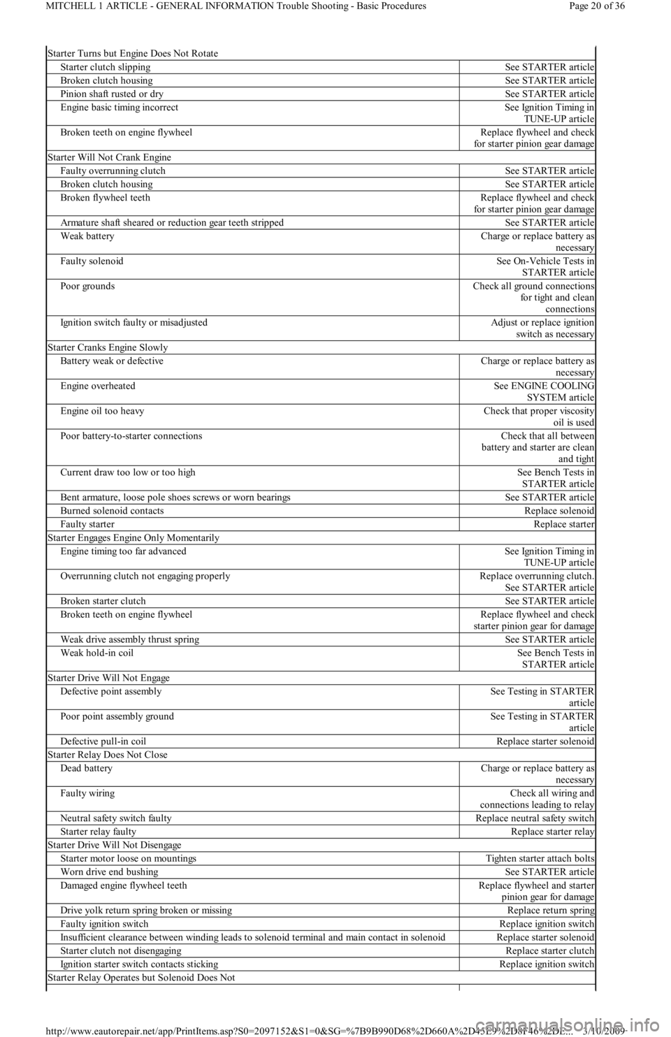
Starter Turns but Engine Does Not Rotate
Starter clutch slippingSee STARTER article
Broken clutch housingSee STARTER article
Pinion shaft rusted or drySee STARTER article
Engine basic timing incorrectSee Ignition Timing in
TUNE-UP article
Broken teeth on engine flywheelReplace flywheel and check
for starter pinion gear damage
Starter Will Not Crank Engine
Faulty overrunning clutchSee STARTER article
Broken clutch housingSee STARTER article
Broken flywheel teethReplace flywheel and check
for starter pinion gear damage
Armature shaft sheared or reduction gear teeth strippedSee STARTER article
Weak batteryCharge or replace battery as
necessary
Faulty solenoidSee On-Vehicle Tests in
STARTER article
Poor groundsCheck all ground connections
for tight and clean
connections
Ignition switch faulty or misadjustedAdjust or replace ignition
switch as necessary
Starter Cranks Engine Slowly
Battery weak or defectiveCharge or replace battery as
necessary
Engine overheatedSee ENGINE COOLING
SYSTEM article
Engine oil too heavyCheck that proper viscosity
oil is used
Poor battery-to-starter connectionsCheck that all between
battery and starter are clean
and tight
Current draw too low or too highSee Bench Tests in
STARTER article
Bent armature, loose pole shoes screws or worn bearingsSee STARTER article
Burned solenoid contactsReplace solenoid
Faulty starterReplace starter
S t a r t e r E n ga ge s E n gin e On l y M o me n t a r il y
Engine timing too far advancedSee Ignition Timing in
TUNE-UP article
Overrunning clutch not engaging properlyReplace overrunning clutch.
See STARTER article
Broken starter clutchSee STARTER article
Broken teeth on engine flywheelReplace flywheel and check
starter pinion gear for damage
Weak drive assembly thrust springSee STARTER article
Weak hold-in coilSee Bench Tests in
STARTER article
Starter Drive Will Not Engage
Defective point assemblySee Testing in STARTER
article
Poor point assembly groundSee Testing in STARTER
article
Defective pull-in coilReplace starter solenoid
Starter Relay Does Not Close
Dead batteryCharge or replace battery as
necessary
Faulty wiringCheck all wiring and
connections leading to relay
Neutral safety switch faultyReplace neutral safety switch
Starter relay faultyReplace starter relay
Starter Drive Will Not Disengage
Starter motor loose on mountingsTighten starter attach bolts
Worn drive end bushingSee STARTER article
Damaged engine flywheel teethReplace flywheel and starter
pinion gear for damage
Drive yolk return spring broken or missingReplace return spring
Faulty ignition switchReplace ignition switch
Insufficient clearance between winding leads to solenoid terminal and main contact in solenoidReplace starter solenoid
Starter clutch not disengagingReplace starter clutch
Ignition starter switch contacts stickingReplace ignition switch
Starter Relay Operates but Solenoid Does Not
Page 20 of 36 MITCHELL 1 ARTICLE - GENERAL INFORMATION Trouble Shooting - Basic Procedures
3/10/2009 http://www.eautorepair.net/app/PrintItems.asp?S0=2097152&S1=0&SG=%7B9B990D68%2D660A%2D45E9%2D8F46%2DE
...