check oil FORD FESTIVA 1991 Service Manual
[x] Cancel search | Manufacturer: FORD, Model Year: 1991, Model line: FESTIVA, Model: FORD FESTIVA 1991Pages: 454, PDF Size: 9.53 MB
Page 2 of 454
Back To Article
INST RUMENT PANEL
1991 ACCESSORIES & SAFET Y EQUIPMENT Ford Motor Co. Switches & Instrum ent Panels - Standard
DESCRIPTION & OPERATION
Instrument panel on Capri contains a speedometer, tachometer, fuel, water temperature, oil pressure and voltmeter gauges. A boost gauge is
incorporated into the tachometer on turbo models. Instrument panel is equipped with indicator/warning lights for charging system, air b ag,
manual shift, seat belt, turn signals, high beam and brakes. A CHECK ENGINE light, located on instrument panel, illuminates if a
computerized engine control fault occurs with engine running.
Instrument panel on Festiva contains a speedometer, fuel and water temperature gauges. Instrument panel is equipped with indicator/warning
lights for charging system, oil pressure, seat belt, rear defogger, turn signals, high beam and brakes. A CHECK ENGINE light, located on
instrument panel, illuminates if a computerized engine control fault occurs with engine running.
TROUBLE SHOOTING
FUEL GAUGE
Fuel Gauge Always Reads Empty
If fuel gauge always reads empty, check these items:
Check fuel gauge for open or damaged wires.
Check for open ground at fuel gauge sending unit.
Check for defective fuel sending unit.
Check for defective fuel gauge.
Check for defective instrument panel voltage regulator (Festiva).
Check for blown 10-amp METER fuse in fuse panel.
Check for open in Black/Yellow power feed wire from fuse panel instrument panel.
Check for fuel tank float full of fuel (sunk).
Fuel Gauge Always Reads Full
If fuel gauge always reads full, check these items:
Check for fuel gauge Yellow wire shorted to ground.
Check for defective fuel sending unit.
Check for defective fuel gauge.
Check for defective instrument panel voltage regulator (Festiva).
Fuel Gauge Inaccurate
If fuel gauge is inaccurate, check these items:
Check for faulty (loose or corroded) wire connections.
Check for defective fuel sending unit.
Check for defective instrument panel voltage regulator (Festiva).
TEMPERATURE GAUGE
Temperature Gauge Always Reads Cold
If temperature gauge always reads cold, check these items:
Check temperature gauge for open wire.
Check for defective temperature sender.
Check for defective temperature gauge.
Check for defective instrument panel voltage regulator (Festiva).
Check for blown 10-amp METER fuse in fuse panel.
Check for open in Black/Yellow power feed wire from fuse panel to instrument panel.
Temperature Gauge Always Reads Hot
CAUT ION: On m odels with Supplem ental Restraint System (SRS), observe safety precautions. T he air bag system
is powered directly from the battery and back-up power supply. Before any repairs are perform ed,
disconnect and shield battery ground cable. Disconnect the back-up power supply BEFORE servicing
ANY air bag com ponent. Use caution when working near steering colum n. Air bag could accidentally
deploy at any tim e.
NOTE:Ensure continuity exists between chassis ground and Black wire of instrum ent panel connector,
especially if fault exists in m ultiple gauge circuits. See appropriate chassis wiring diagram in the
WIRING DIAGRAMS Section.
Page 1 of 5 MITCHELL 1 ARTICLE - INSTRUMENT PANEL 1991 ACCESSORIES & SAFETY EQUIPMENT Ford Motor Co. Switches
...
3/10/2009 http://www.eautorepair.net/app/PrintItems.asp?S0=2097152&S1=0&SG=%7B959286D2%2D3A85%2D4BFC%2D9C5C%2D
...
Page 3 of 454
If temperature gauge always reads hot, check these items:
Check for temperature gauge wire shorted to ground.
Check for defective temperature sender.
Check for defective temperature gauge.
Check for defective instrument panel voltage regulator (Festiva).
Temperature Gauge Inaccurate
If temperature gauge is inaccurate, check these items:
Check for faulty (loose or corroded) wire connections.
Check for defective temperature sender.
Check for defective instrument panel voltage regulator (Festiva).
SPEEDOMETER
Speedometer Does Not Operate
If speedometer does not operate, check these items:
Check for broken speedometer drive cable.
Check for broken drive gear in transmission.
Check for defective speedometer head.
Speedometer Needle Bounces
If speedometer needle bounces, check these items:
Check for binding speedometer drive cable.
Check for missing teeth on drive gear in transmission.
Check for defective speedometer head.
Speedometer Does Not Indicate Correct Vehicle Speed
If speedometer does not indicate correct vehicle speed, check these items:
Check for incorrect size tires.
Check for improper tire inflation.
Check for defective speedometer head.
TACHOMETER (CAPRI)
Tachometer Does Not Work, But All Other Gauges Work Properly
-If tachometer does not work, but all other gauges function properly, check these items:
Check for defective tachometer.
Check for open Yellow/Black tachometer signal wire from ignition coil to instrument panel.
Check for faulty Black ground wire to instrument panel.
Tachometer & All Gauges Do Not Function
If tachometer and all other gauges do not function properly, check these items:
Check for blown 10-amp METER fuse in fuse panel.
Check for open in Black/Yellow wire to fuse panel to instrument panel and Black/White wire from ignition switch to fuse panel
Tachometer Reading Low
If tachometer reading is lower than normal, check these items:
Check for defective tachometer.
Check for faulty Black ground wire at instrument panel.
TURBO BOOST GAUGE (CAPRI)
Turbo Boost Gauge Always Reads Low
If turbo boost gauge always reads low, check these items:
Check boost gauge for open or damaged wires.
Check for defective boost sensing unit.
Check for defective boost gauge.
Check for blown 10-amp METER fuse in fuse panel.
Check for loose or corroded connections.
Page 2 of 5 MITCHELL 1 ARTICLE - INSTRUMENT PANEL 1991 ACCESSORIES & SAFETY EQUIPMENT Ford Motor Co. Switches
...
3/10/2009 http://www.eautorepair.net/app/PrintItems.asp?S0=2097152&S1=0&SG=%7B959286D2%2D3A85%2D4BFC%2D9C5C%2D
...
Page 4 of 454
Turbo Boost Gauge Always Reads High
If turbo boost gauge always reads high, check these items:
Check for damaged White/Black signal wire.
Check for defective boost sensing unit.
Check for defective boost gauge.
Turbo Boost Gauge Inaccurate
If turbo boost gauge is inaccurate, check these items:
Check for loose or corroded connections.
Check for defective boost sensing unit.
Check for defective boost gauge.
TESTING
FUEL GAUGE SENDING UNIT
Capri
Remove rear seat cushion. Disconnect fuel pump/fuel gauge sending unit electrical connector at access cover. Turn ignition on. Fuel gauge
should read empty. Using a jumper wire, connect Yellow fuel gauge wire of vehicle harness connector to ground. Fuel gauge should read full.
If fuel gauge operates as specified, replace fuel gauge sending unit.
Festiva
Remove fuel gauge sending unit from tank. See FUEL SENDING UNIT under REMOVAL & INSTALLATION. Connect an ohmmeter and
check sending unit resistance as indicated in FUEL GAUGE SENDING UNIT RESISTANCE (FESTIVA)
table. Replace sending unit if
resistance is drastically different than specification.
FUEL GAUGE SENDING UNIT RESISTANCE (FESTIVA)
OIL PRESSURE GAUGE (CAPRI)
1. Remove electrical connector from oil pressure sending unit located on right side of engine block. Turn ignition switch on. Oil pressure
gauge should read low. Install a jumper wire between Yellow/Red wire of oil pressure sending unit vehicle harness connector and
ground. Oil pressure gauge should read high.
2. If oil pressure gauge operates as specified, replace sending unit. If gauge does not operate as specified, check instrument panel power
and ground circuits.
OIL PRESSURE WARNING LIGHT (FESTIVA)
Light Stays On With Engine Running
1. Turn ignition on (DO NOT start engine). Disconnect Yellow/Red wire from oil pressure switch connector. Light should go off.
2. If light stays on, repair short in Yellow/Red wire between oil indicator light and oil pressure switch. Reconnect wire to switch. Light
should be on with ignition on. If light does not go off when engine is started, check switch or engine for low oil pressure.
Oil Light Will Not Go On With Ignition On
1. Ground Yellow/Red wire at instrument panel connector. If light goes on, repair Yellow/Red wire between oil pressure switch and
indicator light or replace defective oil pressure switch.
2. If light does not illuminate, check bulb or check instrument panel ground circuit.
TEMPERATURE GAUGE (CAPRI)
1. Remove electrical connector from temperature sending unit located at front of cylinder head. Connect one lead of Gauge System Tester
(021-00055) to connector and other tester lead to ground. Set tester to 18 ohms, turn ignition switch on and observe temperature gauge.
Gauge should read 250°F.
2. Turn tester to 60 ohms. Gauge should read 175°F. Turn tester to 223 ohms. Gauge should read 100°F. If all readings are within twice
the needle width of correct reading, gauge is functioning properly. If readings are not as specified, replace gauge.
TEMPERATURE GAUGE (FESTIVA)
See TROUBLE SHOOTING for possible service areas.
TEMPERATURE SENDING UNIT (CAPRI)
Remove sending unit from engine and place in container of water. Heat water to 176°F (80°C). Measure resistance between sending unit
connector and case. Resistance should be 49.3-57.7 ohms. If resistance is not as specified, replace sending unit. NOTE:Inspect fuel tank for distortion or dam age. If distorted or dam aged, repair or replace tank before testing.
Float PositionOhms
Full Position (Up)Approximately 7
Half-Full Position (Middle)Approximately 33
Empty Position (Down)Approximately 95
Page 3 of 5 MITCHELL 1 ARTICLE - INSTRUMENT PANEL 1991 ACCESSORIES & SAFETY EQUIPMENT Ford Motor Co. Switches
...
3/10/2009 http://www.eautorepair.net/app/PrintItems.asp?S0=2097152&S1=0&SG=%7B959286D2%2D3A85%2D4BFC%2D9C5C%2D
...
Page 6 of 454
2. Lift access plate and disconnect sending unit wiring. To relieve fuel pressure, start engine and run it until engine stalls. Turn ignition off.
Disconnect and plug fuel lines at sending unit. Remove sending u n it a t t a c h in g sc r e ws. R e mo ve se n d in g u n it . To in st a l l , r e ve r se removal
procedure.
TACHOMETER
Removal & Installation
Remo ve in st ru men t p an el . See INSTRUMENT PANEL under REMOVAL & INSTALLATION. Disassemble panel and remove tachometer.
To install tachometer, reverse removal procedure. On Capri, the tachometer/speedometer/boost gauge assembly must be replaced as an
assembly.
TEMPERATURE GAUGE
Removal & Installation
Remo ve in st ru men t p an el . See INSTRUMENT PANEL under REMOVAL & INSTALLATION. Disassemble panel and remove temperature
gauge. To install gauge, reverse removal procedure. On Capri, the temperature/oil pressure gauge assembly must be replaced as an assembly.
TEMPERATURE SENDING UNIT
Removal
Disconnect sending unit wire, located on side of block below thermostat housing (Festiva) or cylinder head (Capri). Remove radiator cap to
relieve cooling system pressure. Position drain pan below sending unit. Remove temperature sending unit.
Installation
To install, apply Pipe Sealant With Teflon (D8AZ-19554-A) to threads of sending unit. Reverse removal procedure to complete installation.
Fill cooling system to proper level. Start engine and check for coolant leaks at sending unit.
WIRING DIAGRAMS
CAUT ION: T achom eter is calibrated at factory. Rough handling could disturb calibration.
NOTE:Refer to the appropriate WIRING DIAGRAMS article in the WIRING DIAGRAMS section.
Copyr ight 2009 Mitchell Repair Information Company, LLC. All Rights Reserved.
Article GUID: A00028301
Page 5 of 5 MITCHELL 1 ARTICLE - INSTRUMENT PANEL 1991 ACCESSORIES & SAFETY EQUIPMENT Ford Motor Co. Switches
...
3/10/2009 http://www.eautorepair.net/app/PrintItems.asp?S0=2097152&S1=0&SG=%7B959286D2%2D3A85%2D4BFC%2D9C5C%2D
...
Page 42 of 454
Installation (All)
1. To install axle shaft, reverse removal procedure. Always install a NEW retaining circlip. Check seals at both ends of axle shaft. If
necessary, replace seals prior to installation. Lubricate transaxle seal lip with transaxle oil. See Fig. 1
.
2. After installing axle shaft into transaxle, pull axle shaft outward by hand to ensure proper engagement of retaining circlip and snap ring.
Install axle shaft into wheel hub. Align suspension alignment marks and tighten nuts.
INTERMEDIATE SHAFT
Removal
Intermediate shaft and axle shaft are removed as an assembly. See FWD AXLE SHAFTS under REMOVAL, DISASSEMBLY,
REASSEMBLY & INSTALLATION.
Disassembly
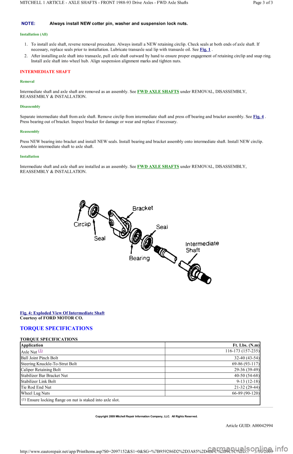
Separate intermediate shaft from axle shaft. Remove circlip from intermediate shaft and press off bearing and bracket assembly. See Fig. 4 .
Press bearing out of bracket. Inspect bracket for damage or wear and replace if necessary.
Reassembly
Press NEW bearing into bracket and install NEW seals. Install bearing and bracket assembly onto intermediate shaft. Install NEW circlip.
Assemble intermediate shaft to axle shaft.
Installation
Intermediate shaft and axle shaft are installed as an assembly. See FWD AXLE SHAFTS under REMOVAL, DISASSEMBLY,
REASSEMBLY & INSTALLATION.
Fig. 4: Exploded View Of Intermediate Shaft
Courtesy of FORD MOTOR CO.
TORQUE SPECIFICATIONS
TORQUE SPECIFICATIONS NOTE:Always install NEW cotter pin, washer and suspension lock nuts.
ApplicationFt. Lbs. (N.m)
Axle Nut (1) 116-173 (157-235)
Ball Joint Pinch Bolt32-40 (43-54)
Steering Knuckle-To-Strut Bolt69-86 (93-117)
Caliper Retaining Bolt29-36 (39-49)
Stabilizer Bar Bracket Nut40-50 (54-68)
Stabilizer Link Bolt9-13 (12-18)
Tie Rod End Nut21-32 (29-44)
Wheel Lug Nuts66-89 (90-120)
(1)Ensure locking flange on nut is staked into axle slot.
Copyr ight 2009 Mitchell Repair Information Company, LLC. All Rights Reserved.
Article GUID: A00042994
Page 3 of 3 MITCHELL 1 ARTICLE - AXLE SHAFTS - FRONT 1988-93 Drive Axles - FWD Axle Shafts
3/10/2009 http://www.eautorepair.net/app/PrintItems.asp?S0=2097152&S1=0&SG=%7B959286D2%2D3A85%2D4BFC%2D9C5C%2D
...
Page 44 of 454
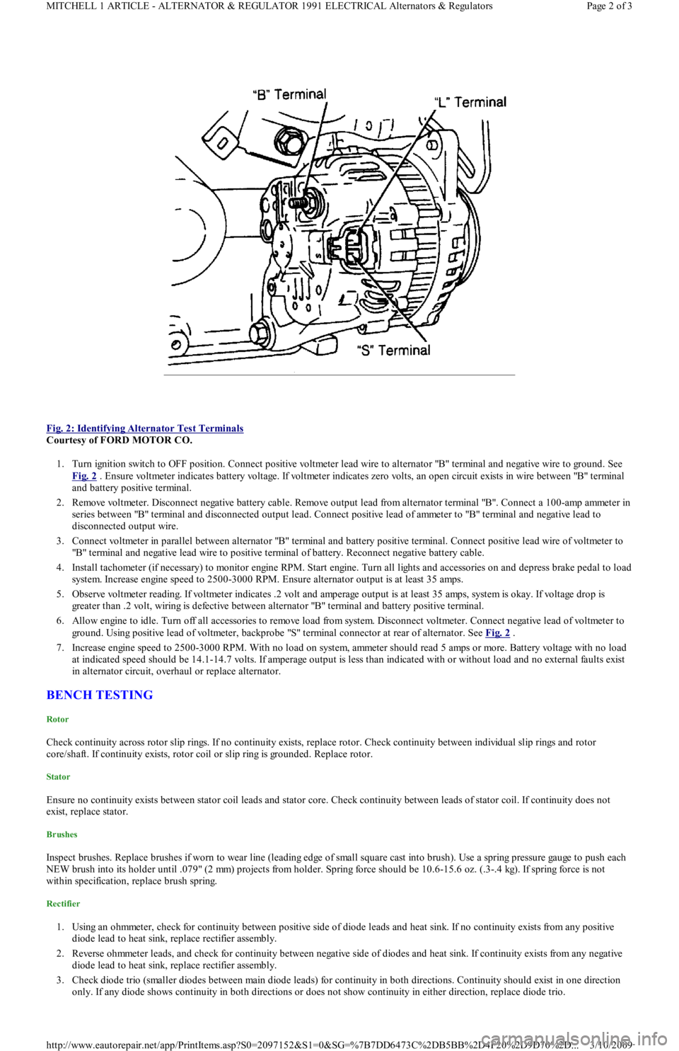
Fig. 2: Identifying Alternator Test Terminals
Courtesy of FORD MOTOR CO.
1. Turn ignition switch to OFF position. Connect positive voltmeter lead wire to alternator "B" terminal and negative wire to ground. See
Fig. 2
. Ensure voltmeter indicates battery voltage. If voltmeter indicates zero volts, an open circuit exists in wire between "B" terminal
and battery positive terminal.
2. Remove voltmeter. Disconnect negative battery cable. Remove output lead from alternator terminal "B". Connect a 100-amp ammeter in
series between "B" terminal and disconnected output lead. Connect positive lead of ammeter to "B" terminal and negative lead to
disconnected output wire.
3. Connect voltmeter in parallel between alternator "B" terminal and battery positive terminal. Connect positive lead wire of voltmeter to
"B" terminal and negative lead wire to positive terminal of battery. Reconnect negative battery cable.
4. Install tachometer (if necessary) to monitor engine RPM. Start engine. Turn all lights and accessories on and depress brake pedal to load
system. Increase engine speed to 2500-3000 RPM. Ensure alternator output is at least 35 amps.
5. Observe voltmeter reading. If voltmeter indicates .2 volt and amperage output is at least 35 amps, system is okay. If voltage drop is
greater than .2 volt, wiring is defective between alternator "B" terminal and battery positive terminal.
6. Allow engine to idle. Turn off all accessories to remove load from system. Disconnect voltmeter. Connect negative lead of voltmeter to
ground. Using positive lead of voltmeter, backprobe "S" terminal connector at rear of alternator. See Fig. 2
.
7. Increase engine speed to 2500-3000 RPM. With no load on system, ammeter should read 5 amps or more. Battery voltage with no load
at indicated speed should be 14.1-14.7 volts. If amperage output is less than indicated with or without load and no external faults exist
in alternator circuit, overhaul or replace alternator.
BENCH TESTING
Rotor
Check continuity across rotor slip rings. If no continuity exists, replace rotor. Check continuity between individual slip rings and rotor
core/shaft. If continuity exists, rotor coil or slip ring is grounded. Replace rotor.
Stator
Ensure no continuity exists between stator coil leads and stator core. Check continuity between leads of stator coil. If continuity does not
exist, replace stator.
Brushes
Inspect brushes. Replace brushes if worn to wear line (leading edge of small square cast into brush). Use a spring pressure gauge to push each
NEW brush into its holder until .079" (2 mm) projects from holder. Spring force should be 10.6-15.6 oz. (.3-.4 kg). If spring force is not
within specification, replace brush spring.
Rectifier
1. Using an ohmmeter, check for continuity between positive side of diode leads and heat sink. If no continuity exists from any positive
diode lead to heat sink, replace rectifier assembly.
2. Reverse ohmmeter leads, and check for continuity between negative side of diodes and heat sink. If continuity exists from any n e ga t ive
diode lead to heat sink, replace rectifier assembly.
3. Check diode trio (smaller diodes between main diode leads) for continuity in both directions. Continuity should exist in one direction
only. If any diode shows continuity in both directions or does not show continuity in either direction, replace diode trio.
Page 2 of 3 MITCHELL 1 ARTICLE - ALTERNATOR & REGULATOR 1991 ELECTRICAL Alternators & Regulators
3/10/2009 http://www.eautorepair.net/app/PrintItems.asp?S0=2097152&S1=0&SG=%7B7DD6473C%2DB5BB%2D4F20%2D9D70%2D
...
Page 53 of 454
3. If voltage is not present or is less than 8 volts at starter solenoid terminal "S", malfunction in circuit to terminal "S" is indicated. Proceed
to the following tests.
IGNITION SWITCH TEST
1. Locate ignition switch connector under dash. Using a 12-volt test light or voltmeter, ensure voltage is present on Black/Yellow wire
when ignition switch is turned to RUN or ON position. This will verify proper operation of ignition switch.
2. If there is no voltage on Black/Yellow wire, the problem is either ignition switch or circuit between battery and ignition switch.
CLUTCH ENGAGE SWITCH (M/T) TEST
Unplug clutch engage switch from main wiring harness. Using an ohmmeter, check for continuity across switch terminals. Continuity should
exist when switch plunger is pushed in and should not exist when switch plunger is released. If clutch engage switch does not operate as
specified, replace switch.
NEUTRAL SAFETY SWITCH (A/T) TEST
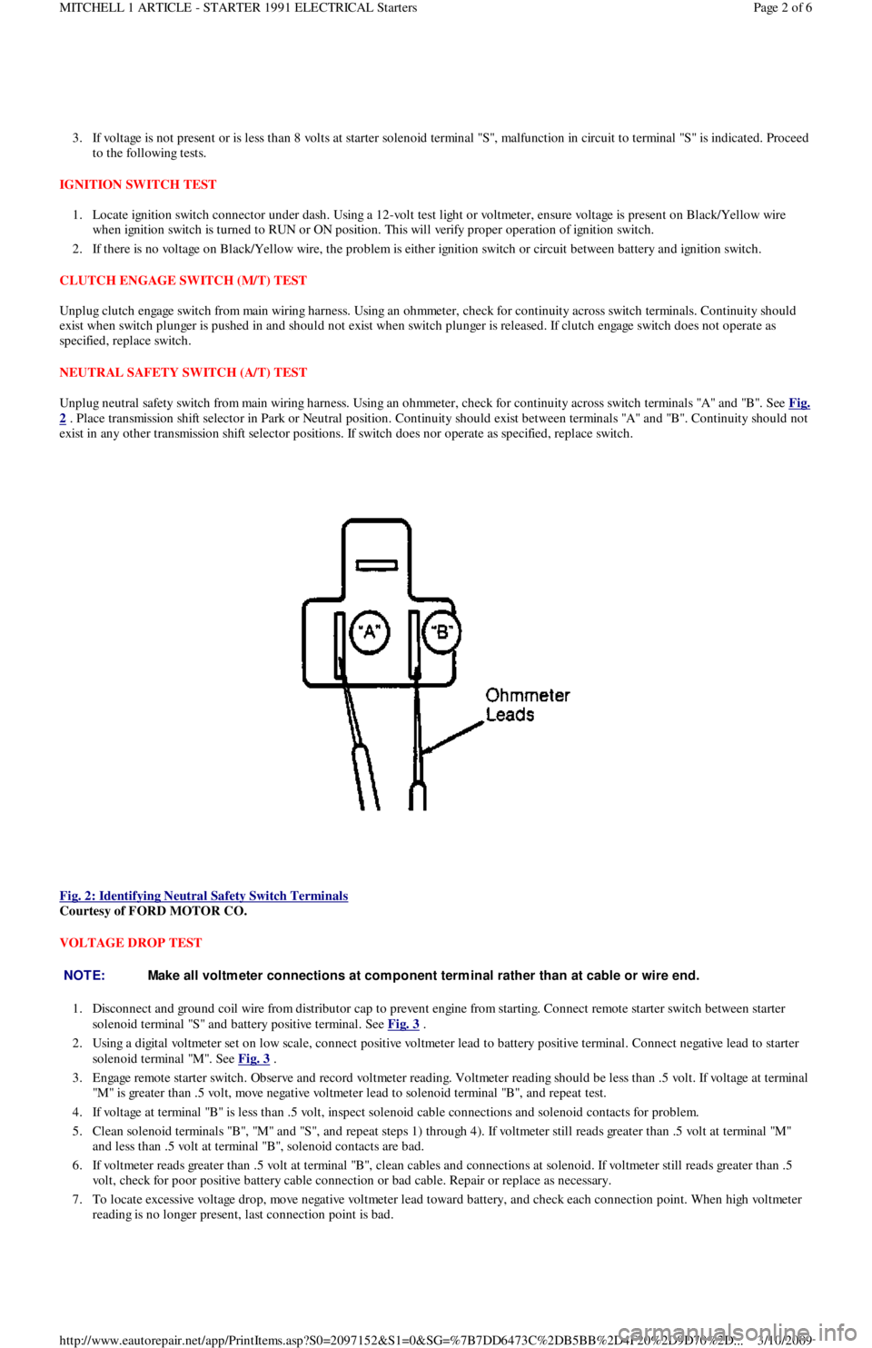
Unplug neutral safety switch from main wiring harness. Using an ohmmeter, check for continuity across switch terminals "A" and "B". See Fig.
2 . Place transmission shift selector in Park or Neutral position. Continuity should exist between terminals "A" and "B". Continuity should not
exist in any other transmission shift selector positions. If switch does nor operate as specified, replace switch.
Fig. 2: Identifying Neutral Safety Switch Terminals
Courtesy of FORD MOTOR CO.
VOLTAGE DROP TEST
1. Disconnect and ground coil wire from distributor cap to prevent engine from starting. Connect remote starter switch between starter
solenoid terminal "S" and battery positive terminal. See Fig. 3
.
2. Using a digital voltmeter set on low scale, connect positive voltmeter lead to battery positive terminal. Connect negative lead to starter
solenoid terminal "M". See Fig. 3
.
3. Engage remote starter switch. Observe and record voltmeter reading. Voltmeter reading should be less than .5 volt. If voltage at terminal
"M" is greater than .5 volt, move negative voltmeter lead to solenoid terminal "B", and repeat test.
4. If voltage at terminal "B" is less than .5 volt, inspect solenoid cable connections and solenoid contacts for problem.
5 . Cl ean so l en o id t ermin al s "B", "M" an d "S", an d rep eat st ep s 1 ) through 4). If voltmeter still reads greater than .5 volt at termin al "M"
and less than .5 volt at terminal "B", solenoid contacts are bad.
6. If voltmeter reads greater than .5 volt at terminal "B", clean cables and connections at solenoid. If voltmeter still reads greater than .5
volt, check for poor positive battery cable connection or bad cable. Repair or replace as necessary.
7. To locate excessive voltage drop, move negative voltmeter lead toward battery, and check each connection point. When high voltmeter
reading is no longer present, last connection point is bad.
NOTE:Make all voltm eter connections at com ponent term inal rather than at cable or wire end.
Page 2 of 6 MITCHELL 1 ARTICLE - STARTER 1991 ELECTRICAL Starters
3/10/2009 http://www.eautorepair.net/app/PrintItems.asp?S0=2097152&S1=0&SG=%7B7DD6473C%2DB5BB%2D4F20%2D9D70%2D
...
Page 56 of 454
SOLENOID TEST
Disconnect wiring and cables from solenoid. Using an ohmmeter, check for continuity between terminal "M" and body of starter solenoid. See
Fig. 1
. Continuity should exist. If continuity does not exist, replace solenoid.
ARMATURE TEST
1. Place armature in growler. Turn on growler and hold a piece of hacksaw blade over armature. Slowly rotate armature. If hacksaw blade
is attracted to core or if it vibrates, replace armature.
2. Remove armature from growler. Using an ohmmeter, check continuity between commutator and core. If continuity exists, replace
armature. Check continuity between commutator and shaft. If continuity exists, replace armature.
3. Check continuity between each commutator segment. If an open exists between any 2 segments, replace armature.
COMMUTATOR TEST
1. Clean surface of commutator and polish with No. 400 grit sandpaper (if required). If surface is scored, out of round or pitted, turn
commutator on a lathe.
2. Maximum commutator runout and minimum diameter of commutator must not exceed specification after turning. See STARTER
MOTOR SPECIFICATIONS table.
3. Commutator mica undercut depth should be .02-.03" (.5-.8 mm). If undercut depth is not within specification, undercut with a hacksaw
blade to standard depth.
BRUSH & SPRING TEST
1. Connect ohmmeter between positive brush holder and negative brush holder. If ohmmeter indicates continuity, brush holder assemb l y is
shorted and must be replaced.
2. Check brush length. See STARTER MOTOR SPECIFICATIONS
table. If brush length is less than specification, replace brushes.
3. Check spring tension. Spring tension should be 2.0-4.3 Lbs. (8.8-19.1 N.m). Ensure brushes move freely in holders.
FIELD COIL TEST
1. Connect ohmmeter between field lead and soldered portion of brush lead. If continuity does not exist, repair or replace field coil.
2. Check field coil for shorts to ground by connecting ohmmeter between field lead and starter housing. If continuity exists, repair or
replace field coil.
OVERHAUL
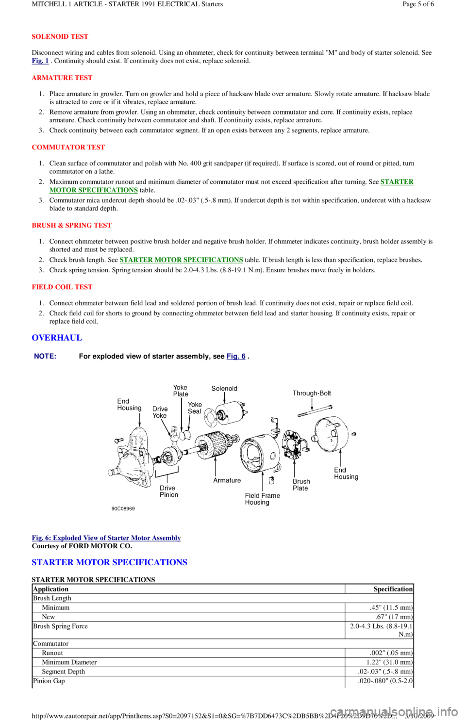
Fig. 6: Exploded View of Starter Motor Assembly
Courtesy of FORD MOTOR CO.
STARTER MOTOR SPECIFICATIONS
STARTER MOTOR SPECIFICATIONS NOTE:For exploded view of starter assem bly, see Fig. 6
.
ApplicationSpecification
Brush Length
Minimum.45" (11.5 mm)
New.67" (17 mm)
Brush Spring Force2.0-4.3 Lbs. (8.8-19.1
N.m)
Commutator
Runout.002" (.05 mm)
Min imu m Diamet er1.22" (31.0 mm)
Segment Depth.02-.03" (.5-.8 mm)
Pinion Gap.020-.080" (0.5-2.0
Page 5 of 6 MITCHELL 1 ARTICLE - STARTER 1991 ELECTRICAL Starters
3/10/2009 http://www.eautorepair.net/app/PrintItems.asp?S0=2097152&S1=0&SG=%7B7DD6473C%2DB5BB%2D4F20%2D9D70%2D
...
Page 103 of 454
Disconnect negative battery cable. Drain cooling system. Remove air cleaner. Remove intake manifold bracket. Disconnect throttle cable.
Mark and disconnect vacuum hoses, fuel hoses and wiring. Remove intake manifold bolts. Remove intake manifold and gasket.
Installation (1.3L)
Clean all gasket mating surfaces. Ensure surface is free of burrs, scratches and cracks. Replace all gaskets. Position gasket and manifold to
cylinder head. Install bolts and tighten to specification. To complete installation, reverse removal procedure.
Removal (1.6L)
1. Disconnect negative battery terminal. Relieve fuel pressure. See FUEL PRESSURE RELEASE under REMOVAL &
INSTALLATION. Drain cooling system. Disconnect intercooler tube and/or air intake tube. Disconnect air by-pass hoses. Disconnect
main engine harness electrical connection and TPS connector. Disconnect vacuum hoses from throttle body.
2. Disconnect fuel lines from fuel filter and pressure regulator. Disconnect throttle cable. Disconnect hoses from By-pass Air Control valve
( B AC ) . R e mo ve B AC va l ve r e t a in in g n u t a n d b o l t . R e mo ve in t a ke manifold retaining nuts and bolts from support bracket and cylinder
head. Remove intake manifold and throttle body assembly.
Installation (1.6L)
1. Install new intake manifold gasket, ensuring coolant passage openings align with openings in cylinder head and manifold. Install intake
manifold. Tighten retaining nut and bolts and support bracket bolts to specification. See TORQUE SPECIFICATIONS
table at end of
article.
2. Install BAC valve and connect air hoses. Connect throttle cable. Connect fuel lines to fuel filters and pressure regulator. Connect main
engine harness connector and TPS connector. Connect vacuum lines to throttle body. Install intake air tube. Connect intercooler tube
and/or intake air tube. Connect air by-pass hoses. Fill cooling system. Connect negative battery terminal. Start engine and check for
fluid leaks and correct operation.
EXHAUST MANIFOLD
Removal (1.3L)
1. Raise vehicle. Remove catalytic converter inlet pipe at exhaust manifold. Remove pulse air tube nuts at inlet pipe. Remove inlet pipe
support bracket bolts. Lower vehicle. Remove air intake duct. Remove exhaust manifold heat shroud bolts and remove shroud.
2. Disconnect oxygen sensor connector. Remove exhaust manifold nuts and remove exhaust manifold. Remove gasket from inlet pipe and
cylinder head.
Installation
Position new gasket on cylinder head and inlet pipe. Install exhaust manifold and nuts. Tighten nuts to specification. See, at end of article,
TORQUE SPECIFICATIONS
table. To complete installation, reverse removal procedure. Tighten all bolts and nuts to specification.
Removal (1.6L Non-Turbo)
Remove intake air tube. Remove front exhaust pipe to exhaust manifold retaining nuts. Remove exhaust support bracket (if equipped). Remove
heat shield. Disconnect O2 sensor electrical connector. Remove exhaust manifold.
Installation (1.6L Non-Turbo)
Install exhaust manifold gaskets. Install heavier gasket first. Install exhaust manifold and tighten retaining nuts to specification. See TORQUE
SPECIFICATIONS table at end of article. Connect O2 sensor electrical connector. Install manifold heat shield. Install intake air tube.
Connect front exhaust pipe to intake manifold and tighten retaining nuts to specification. Install exhaust support bracket, if removed, and
tighten engine mount bolt to specification. Start engine and check for leaks.
Removal (1.6L Turbo)
1. Disconnect negative battery cable. Drain cooling system. Remove throttle body air intake tube. Disconnect intercooler hose from
turbocharger assembly and position both intercooler hoses out of the way. Remove O2 sensor connector from its retaining clip, and
disconnect O2 sensor. Remove lower heat shield and then upper heat shield. Remove turbocharger side heat shield.
2. Remove power steering pump (leave hoses attached) and lay aside. Disconnect lower radiator hose from water pump. Position power
steering pump to access mounting bracket retaining bolts and nut. Remove both bolts and one nut, and remove bracket from engine.
Remove 2 screws retaining air cleaner duct tube, loosen clamp at turbocharger and position duct tube out of the way. Disconnect
coolant return hose at turbocharger. Remove bolt and brass sealing washers from oil supply line at engine block.
3. Raise vehicle. Remove retaining nuts and washers from exhaust pipe flange. Remove 2 bolts retaining exhaust hangers to engine block.
Slide off two rubber exhaust hangers at catalytic converter. Pull exhaust pipe downward and to LH side of vehicle. Disconnect oil return
hose at turbocharger. Disconnect coolant return hose at turbocharger. Remove 2 retaining bolts from turbocharger support bracket.
Remove 2 bolts retaining coolant by-pass tube outlet to water pump. Lower vehicle.
4. Loosen retaining clamp bolt on coolant by-pass tube at rear of cylinder head. Remove 11 retaining nuts from exhaust manifold. Pull
coolant by-pass tube bracket from exhaust stud, and position tube out of way. Grasp manifold, pull off studs and move assembly slightly
to RH side of engine compartment to clear cooling fan, and remove assembly from vehicle.
5. Working on bench, remove 4 nuts retaining turbocharger to exhaust manifold, separate assembly and discard gasket.
Installation (1.6L Turbo)
NOTE:Feed O2 sensor wire and guide through upper heat shield.
NOTE:When reinstalling turbocharger, thoroughly rem ove all gaskets and sealant. Use new gaskets. Add .85
oz. (25 cc) of engine oil in the oil passage of the turbocharger.
Page 3 of 19 MITCHELL 1 ARTICLE - ENGINE OVERHAUL 1991-92 FORD MOTOR CO. ENGINES 1.3L & 1.6L 4-Cylinder
3/10/2009 http://www.eautorepair.net/app/PrintItems.asp?S0=2097152&S1=0&SG=%7B959286D2%2D3A85%2D4BFC%2D9C5C%2D
...
Page 104 of 454
1. Position new gasket on exhaust manifold, and install turbocharger onto studs. Install 4 retaining nuts and tighten to specification. See
TORQUE SPECIFICATIONS
table at end of article.
2. Remove oil supply line from turbocharger. Position new (2-piece) exhaust gasket on cylinder head with heavy gasket installed first .
Carefully position turbocharger assembly in engine compartment and slide exhaust manifold on studs. Position heater tube bracket onto
exhaust stud. Install 11 retaining nuts onto exhaust manifold and tighten to specification. See TORQUE SPECIFICATIONS
table at
end of article. Tighten heater tube clamp bolt securely.
3. Raise vehicle. Position new gasket and install 2 retaining bolts on heater tube outlet. Install 2 retaining bolts into turbocharger support
bracket and tighten bolts to specification.
4. Connect coolant return hose. Connect oil return hose and secure with clamp. Position exhaust pipe onto turbocharger, and start nuts
and washers. Install 2 retaining bolts on exhaust hanger at engine. Slide on 2 rubber exhaust hangers at catalytic converter. Tighten
exhaust pipe retaining nuts to specification. Lower vehicle.
5. Install retaining bolt and brass washers on oil supply line, carefully position oil line into vehicle and hand-start bolt into engine block.
Connect and finger tighten oil line to turbocharger. Tighten oil line bolt and oil supply line on turbocharger to specification.
6. Connect coolant supply hose. Position air cleaner duct tube on turbocharger and tighten clamp. Install 2 screws retaining air cleaner
duct tube. Position power steering pump bracket on engine, and install 2 retaining bolts and one retaining nut. Tighten to specification.
Position power steering pump on mounting bracket, and install though bolt and adjuster. Connect lower radiator hose. Install power
steering belt. Position upper heat shield and install 2 retaining bolts finger tight.
7. Position lower heat shield and install three retaining bolts finger tight. Tighten all heat shield bolts to specification. Connect O2 sensor
and install connector into its retaining clip. See TORQUE SPECIFICATIONS
table at end of article. Position intercooler hose on
turbocharger and secure with clamp. Install throttle body air intake tube. Connect negative battery cable. Refill cooling system.
CYLINDER HEAD
Removal (1.3L)
1. Disconnect battery ground cable. Mark and disconnect fuel lines at fuel pump. Remove accessory belts, water pump pulley, crankshaft
pulley, timing belt covers, timing belt tensioner, timing belt, valve cover and exhaust and intake manifolds. Drain cooling system.
2. Mark and remove electrical connectors and vacuum hoses. Remove spark plug wires from spark plugs, and remove spark plugs. Remove
distributor cap. Disconnect vacuum hoses and distributor wiring.
3. Index distributor-to-mount position and remove hold-down bolt. Remove distributor assembly. Remove engine ground strap. Remove
front and rear engine lifting hooks. Remove upper radiator hose, by-pass hose and bracket.
4. Remove bolts retaining rocker arm shaft. Remove rocker arm assemblies. Remove cylinder head bolts. Remove head and gasket.
Inspection (1.3L)
1. Thoroughly clean and check gasket mating surface of cylinder head and block. Check cylinder for cracks, nicks, burrs or damage. Using
a straightedge and feeler gauge, check warpage over entire gasket area. Ensure cylinder head and/or block warpage does not
exceed .006" (.15 mm).
2. If warpage exceeds .006" (.15 mm), machine cylinder head and/or block gasket surface. Maximum machining allowed is .008" (.20 mm).
If more machining is required, replace block and/or cylinder head.
Installation (1.3L)
1. Place new head gasket properly on block. Carefully place cylinder head in position on block. Install head bolts. Tighten bolts in
sequence and in 2 steps. See Fig. 1
.
2. While tightening rocker arm shaft, slide shaft springs away from retaining bolt to prevent pinching springs. Tighten rocker arm shaft bolts
in sequence and to specification. See Fig. 5
. To complete installation, reverse removal procedure. Tighten all bolts/nuts to
specification. Fill all fluids to proper levels. NOTE:T urbocharger-to-exhaust m anifold m ounting nuts are of special quality. Ensure correct nuts are
used.
NOTE:Ensure one brass washer is positioned on each side of oil line fitting.
NOTE:Feed O2 sensor wire through upper heat shield. Install wire retainer under LH bolt.
NOTE:If turbocharger was replaced: Disconnect ignition coil, crank engine for 20 seconds, connect ignition
coil, start engine and run at idle for 30 seconds and check for leaks.
NOTE:If original tim ing belt is being reused, m ark direction of rotation for installation reference.
Page 4 of 19 MITCHELL 1 ARTICLE - ENGINE OVERHAUL 1991-92 FORD MOTOR CO. ENGINES 1.3L & 1.6L 4-Cylinder
3/10/2009 http://www.eautorepair.net/app/PrintItems.asp?S0=2097152&S1=0&SG=%7B959286D2%2D3A85%2D4BFC%2D9C5C%2D
...