fuse box FORD FESTIVA 1991 Service Manual
[x] Cancel search | Manufacturer: FORD, Model Year: 1991, Model line: FESTIVA, Model: FORD FESTIVA 1991Pages: 454, PDF Size: 9.53 MB
Page 12 of 454
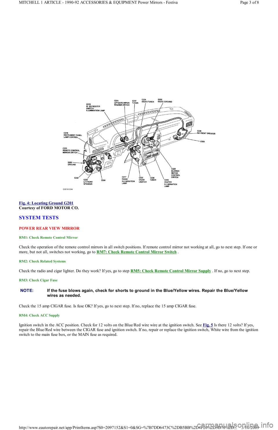
Fig. 4: Locating Ground G201
Courtesy of FORD MOTOR CO.
SYSTEM TESTS
POW ER REAR VIEW MIRROR
RM1: Check Remote Control Mirror
Check the operation of the remote control mirrors in all switch positions. If remote control mirror not working at all, go to next step. If one or
more, but not all, switches not working, go to RM7: Check Remote Control Mirror Switch
.
RM2: Check Related Systems
Check the radio and cigar lighter. Do they work? If yes, go to step RM5: Check Remote Control Mirror Supply . If no, go to next step.
RM3: Check Cigar Fuse
Check the 15 amp CIGAR fuse. Is fuse OK? If yes, go to next step. If no, replace the 15 amp CIGAR fuse.
RM4: Check ACC Supply
Ignition switch in the ACC position. Check for 12 volts on the Blue/Red wire wire at the ignition switch. See Fig. 5 Is there 12 volts? If yes,
repair the Blue/Red wire between the CIGAR fuse and ignition switch. If no, repair or replace the ignition switch, White wire from the ignition
switch to the main fuse box, or the MAIN fuse as required.
NOTE:If the fuse blows again, check for shorts to ground in the Blue/Yellow wires. Repair the Blue/Yellow
wires as needed.
Page 3 of 8 MITCHELL 1 ARTICLE - 1990-92 ACCESSORIES & EQUIPMENT Power Mirrors - Festiva
3/10/2009 http://www.eautorepair.net/app/PrintItems.asp?S0=2097152&S1=0&SG=%7B7DD6473C%2DB5BB%2D4F20%2D9D70%2D
...
Page 18 of 454
Back To Article
ST EERING COLUMN SWIT CHES
1991 ACCESSORIES & SAFET Y EQUIPMENT Ford Motor Co. Steering Colum n Switches
DESCRIPTION & OPERATION
DISABLING AIR BAG SYSTEM
To disable SRS, disconnect battery cable. Unplug back-up power supply 3-way harness connector. System is now disabled. Back-up power
supply is mounted to inside of instrument panel, left of glove box opening. Glove box door must be opened past its stops and lowered toward
floor to access back-up power supply.
ACTIVATING AIR BAG SYSTEM
To activate SRS, reconnect back-up power supply connector and negative battery cable. From passenger's side of vehicle, turn ignition switch
to RUN position. System is now activated. Check AIR BAG light to ensure system is functioning properly.
TESTING
HAZARD WARNING SWITCH & TURN SIGNAL SWITCH
Capri
1. Remove steering column covers to access turn signal/hazard switch connectors. Turn ignition on. Using a 12-volt test light, ensure
battery voltage is present at Green/Red and Green/Yellow wires at turn signal/hazard switch connectors. If battery voltage is not present,
check METER and HAZARD fuses. Also check hazard and turn signal flasher units and replace as necessary.
2. If battery voltage is present at Green/Red and Green/Yellow wires, place turn signal switch in RIGHT position. Check both Green/White
wires at switch connector. Test light should flash on and off in constant cycles.
3. Place turn signal switch in LEFT position. Check both Green/Black wires at switch connector. Test light should flash on and off in
constant cycles. If turn signal/hazard switch does not function as specified, replace switch.
Festiva
1. Remove steering column covers to access turn signal/hazard switch connectors. Turn ignition on. Using a 12-volt test light, ensure
battery voltage is present at White/Black and Black/Yellow wires at hazard and turn signal switch connectors. If battery voltage is not
present, check METER and HAZARD fuses.
2. If battery voltage is present at White/Black and Black/Yellow wires, place turn signal/hazard switch in RIGHT position. Check
Green/Black wire at switch connector. Test light should flash on and off in constant cycles.
3. Place turn signal/hazard switch in LEFT position. Check Green/White wire at switch connector. Test light should flash on and off in
constant cycles. If turn signal/hazard switch does not function as specified, replace switch.
HEADLIGHT SWITCH
Capri
1. Remove instrument panel bezel to access switch connector. See HEADLIGHT SWITCH under REMOVAL & INSTALLATION.
Disconnect switch electrical connector. Measure voltage between Red and Red/White wires of headlight switch vehicle harness and
ground. If battery voltage is present, go to next step. If battery voltage is not present, check HEAD and MAIN fuses and Red and
Red/White wires between switch and fuse block.
2. Press headlight switch to first position. Using a self powered test light or ohmmeter, check continuity between switch terminals which
correspond to Red and Red/Green wires of vehicle harness connector. Continuity should not exist. If continuity exists, replace switch.
3. Press headlight switch to second position. Check continuity between switch terminals which correspond with the Red and Red/Green
wires of vehicle harness connector. Continuity should exist. If switch does not function as described, replace headlight switch. If swit ch
functions as described but headlights do not work, go to next step.
4. Remove steering column covers to access Flash-To-Pass switch connector. Using a 12-volt test light or voltmeter, place switch in
position indicated in table and check voltage between indicated wire terminals and ground. See FLASH-TO-PASS SWITCH TEST
(CAPRI) table. If switch does not function as indicated, replace switch.
FLASH-TO-PASS SWITCH TEST (CAPRI) CAUTION: On Capri m odels with Supplem ental Restraint System (SRS), observe safety precautions. T he air bag
system is powered directly from the battery and back-up power supply. Before any repairs are
perform ed, disconnect and shield battery ground cable. Disconnect the back-up power supply and wait
at least 15 m inutes BEFORE servicing ANY air bag com ponent. Use caution when working near steering
colum n. Air bag could accidentally deploy at any tim e.
NOTE:T he following disabling sequence is ONLY for com ponent replacem ent purposes.
Switch PositionWire ColorVoltage
Off
Headlights OffREDBattery
"All other wires0
Headlights OnRED, RED/GRN,
RED/BLKBattery
"All other wires0
On
Page 1 of 5 MITCHELL 1 ARTICLE - STEERING COLUMN SWITCHES 1991 ACCESSORIES & SAFETY EQUIPMENT Ford Motor C
...
3/10/2009 http://www.eautorepair.net/app/PrintItems.asp?S0=2097152&S1=0&SG=%7B7DD6473C%2DB5BB%2D4F20%2D9D70%2D
...
Page 345 of 454
Back To Article
HEAT ER SYST EM
1990-92 HEAT ER SYST EMS Ford Motor Co.
DESCRIPTION
The heater system consists of control panel, blower case, heater case, air control doors and ducts. The control panel incorporates 3 control
levers and a 3-speed fan switch. The control panel is located in the center of the instrument panel. All air control doors are cable operated
from the control panel.
The blower case is mounted on the bulkhead, behind the instrument panel on passenger's side of vehicle. The blower case houses a blower
motor, blower motor resistor and the fresh/recirculation air door. The heater case contains mode select door, temperature air mix door and
heater core.
OPERATION
Three control levers, temperature mix, fresh/recirculation and mode select, mechanically operate their associated cables and doors. The
temperature control lever adjusts the mix of fresh or recirculated air with heated air. In full heat position, all airflow goes through the heater
core.
In full cool position, the mix air door closes, allowing airflow to by-pass the heater core. The mode select lever, directs airflow to selected
vents. The fresh/recirculation control lever allows selection of fresh (outside) air or recirculated compartment air.
AJUSTMENT
FRESH/RECIRCULATION CONTROL CABLE
Remove the glove box. Remove fresh/recirculation cable retaining clip. Move control lever to RECIRCULATION position, while holding the
lever door in RECIRCULATION position. Ensure control lever does not move. Install fresh/recirculation cable retaining clip.
MODE SELECT CABLE
Remove mode select cable retaining clip. Move mode select lever to VENT position. Hold mode select lever downward against its stop.
Ensure that mode select lever does not move. Install mode select cable retaining clip.
TEMPERATURE CONTROL CABLE
Set temperature control lever to maximum cold position. Remove temperature cable retaining clip. Hold temperature control lever upward and
against its stop. Ensure that temperature lever does not move. Install temperature cable retaining clip.
TROUBLE SHOOTING
BLOWER MOTOR INOPERATIVE
Check blown motor fuse. Check for defective blower motor and/or blower motor resistor. Check blower motor switch. Check for open in
ground wire. Check for loose electrical connectors or poor connections. See WIRING DIAGRAMS
in this article.
BLOWER DOES NOT CHANGE SPEED
Check for defective blower motor. Check blower motor wiring harness. Check blower motor resistor. Check for blower motor fan switch. See
WIRING DIAGRAMS
in this article.
BLOWER RUNS CONSTANTLY
Check for defective blower motor resistor. Check for short in blower switch or wiring. See WIRING DIAGRAMS
in this article.
HEATER TEMPERATURE INSUFFICIENT
Check for proper coolant level. Check water pump for noise, leaks or wear. Check heater hoses for leaks or restrictions. Check heater core for
leaks, plugs or restrictions. Check inlet and outlet heater hoses for hot water flow. Check thermostat condition and operation. Check air mix
door position and adjust cable if necessary.
IMPROPER WARM AIR DISTRIBUTION
Check air mix door position. Adjust cable as necessary. Check function control door position. Adjust cable as necessary. Check for restriction
in ventilation air duct assembly. Repair as necessary.
TESTING BLOWER MOTOR & RESISTOR
1. Ensure 15-amp blower motor fuse is okay. Using voltmeter, check for battery voltage at blower motor Blue/Yellow terminal. If battery
voltage is present, go to next step. If battery voltage is not present, repair open in Blue/Yellow wire between blower motor and fuse box.
2. Disconnect blower motor connector. Using a jumper wire, apply battery voltage to Blue/Yellow terminal and ground the Blue/Red
terminal. If blower motor does not run, replace blower motor. If blower motor runs, go to next step.
3. Reconnect blower motor connector. Turn ignition on. Turn blower motor off. Disconnect the blower motor resistor connector. Using a
voltmeter, measure voltage at Blue/Red terminal of resistor connector. If battery voltage is not present, repair open in Blue/Red wire
between resistor and blower motor. If voltage is present, go to next step.
4. Using a jumper wire, ground Blue/Black, Blue/Yellow and Blue/White terminals of the blower fan switch one at a time. If the motor
runs at 3 different speeds, go to next step. If not, repair open in wire that failed to operate blower motor.
Page 1 of 4 MITCHELL 1 ARTICLE - HEATER SYSTEM 1990-92 HEATER SYSTEMS Ford Motor Co.
3/10/2009 http://www.eautorepair.net/app/PrintItems.asp?S0=2097152&S1=0&SG=%7B9B990D68%2D660A%2D45E9%2D8F46%2DE
...
Page 346 of 454
5. Check blower motor fan switch continuity. Resistance should not exceed 4 ohms. See BLOWER MOTOR FAN SWITCH
CONTINUITY table. If continuity is not present, replace fan switch. If continuity is okay, repair open in Black wire from blower motor
switch to ground.
BLOWER MOTOR FAN SWITCH CONTINUITY
REMOVAL & INSTALLATION
CONTROL PANEL
1. Remove bezel screws and accessory bezel. Remove radio. Remove 4 screws securing control panel to instrument panel. Remove glove
box attaching screws and glove box. Remove the retaining clip and disconnect fresh/recirculation air door cable from mode door lever.
2. Disconnect mode select cable at mode control door lever. Disconnect temperature control cable at temperature control mode door lever.
Pull control panel away from instrument panel. Disconnect blower motor switch connector. Disconnect illumination electrical
connector. Remove control panel. To install, reverse removal procedure. Adjust control cables. See ADJUSTMENTS in this article.
BLOWER MOTOR FAN SWITCH
Remove control panel. See CONTROL PANEL R & I
. Remove blower motor fan switch knob. Remove attaching nut. To install, reverse
removal procedure.
HEATER CORE
1. Disconnect negative battery cable. Remove steering wheel by prying out center trim insert and removing steering wheel retaining nut.
Remove 2 steering wheel cover retaining screws and remove cover. Using a steering wheel puller, remove steering wheel.
2. Remove 5 screws and remove lower and upper steering column covers. Disconnect electrical connections and remove multifunction
switch. Remove 5 screws and pull instrument cluster hood rearward. Disconnect electrical connections and remove instrument cluster
hood.
3. Disconnect speedometer cable at transaxle. Remove 4 instrument cluster screws. Pull instrument cluster rearward and disconnect
speedometer cable and electrical connections. Remove instrument cluster.
4. Remove 2 center bracket mounting bolts under steering column and remove bracket. Remove glove box attaching screws and remove
glove box. Remove left and right heater ducts. Remove fuse panel cover. Remove 2 screws securing fuse panel and push fuse panel
inward. DO NOT remove fuse panel.
5. Slide both seats to most forward position. Remove 2 console attaching screws, located in front of seat belt anchors. Slide both seats to
rearmost position. Remove parking brake console insert. Using a Phillips screwdriver, remove push retainer insert, located at front lower
edge of parking brake console. Pull back on parking brake lever and remove parking brake console.
6. Remove gearshift knob. Remove screws and remove shift console. Remove radio/heater control panel bezel screws and remove bezel.
Remove 4 radio attaching screws. Pull radio out and disconnect antenna lead and electrical connections. Disconnect radio ground lead
and remove radio.
7. Remove 4 screws attaching heater control panel. Disconnect control cables and electrical connections. Remove control panel, while
pulling cables through opening.
8. Pry out bolt cover trim inserts in top corners of dash. Remove bolts located under trim panels. Remove 7 instrument panel attaching
bolts and 2 nuts. Pull instrument panel rearward. Disconnect any harness connectors and clips. Remove instrument panel.
9. Disconnect electrical connections at blower and resistor. Remove harness from routing brackets on heater box. Loosen clamp screw
securing air inlet housing. Remove attaching nuts at top and bottom of heater box. Disconnect defroster ducts and remove heater
assembly.
10. Disconnect link connecting 2 defroster doors. Remove attaching screw just above and to right of blower resistor. Turn heater assembly
around and remove screw just to left of blower motor opening. Remove clips securing 2 halves of heater assembly. Separate halves. Lift
out heater core.
11. To install, reverse removal procedure. Ensure all heater control cables are routed and adjusted properly. See ADJUSTMENTS in this
article. Fill cooling system. Check for leaks.
BLOWER MOTOR & RESISTOR
Disconnect negative battery cable. Remove instrument panel spacer brace located below steering column. Remove airflow duct below steering
column. Disconnect blower motor or resistor wiring. Remove 3 blower motor attaching screws or 2 resistor attaching screws and remove
component. To install, reverse removal procedure.
Switch PositionContinuity Between Wire Colors
1Black-to-Blue/White
2Black-to-Blue/Yellow & Blue/Yellow-to-Blue/Red
3Black-to-Blue/Black & Blue/Black-to-Blue/Red
Page 2 of 4 MITCHELL 1 ARTICLE - HEATER SYSTEM 1990-92 HEATER SYSTEMS Ford Motor Co.
3/10/2009 http://www.eautorepair.net/app/PrintItems.asp?S0=2097152&S1=0&SG=%7B9B990D68%2D660A%2D45E9%2D8F46%2DE
...
Page 361 of 454
tube from evaporator core fins while removing thermostatic switch. To install, reverse removal procedure. Evacuate and recharge system.
THERMOSTATIC EXPANSION VALVE
Removal & Installation
1. Discharge A/C system using approved refrigerant recovery/recycling equipment. Remove evaporator housing. See EVAPORATOR
HOUSING under REMOVAL & INSTALLATION. Remove air inlet duct. See Fig. 1 .
2. Remove insulation from sensing bulb. Disconnect thermostatic expansion valve at evaporator tube fitting and inlet tube fitting (from
receiver-drier). See Fig. 3
. Remove thermostatic expansion valve. To install, reverse removal procedure. Use new "O" rings. Evacuate
and recharge system.
A/C RELAYS
Removal & Installation
A/C relays are located in left front corner of engine compartment, near battery. Unclip relay holder from its mounting bracket. Disconnect
relay wiring. DO NOT pull on wiring connector to remove relay from holder. Remove relay from holder. To install, reverse removal procedure.
A/C-HEATER CONTROL ASSEMBLY
Removal & Installation
1. A/C control module is located above radio. Remove accessory bezel. Remove radio (if necessary) and glove box. Disconnect
recirculated/fresh air cable from door lever. See Fig. 5
. Disconnect mode select cable from door lever. See Fig. 6 .
2. Disconnect temperature control cable from door lever. See Fig. 4
. Pull control assembly away from dash, and disconnect wiring
connectors. Remove control assembly.
3. To install, reverse removal procedure. Check and adjust temperature control, recirculated/fresh air and mode cables. See
ADJUSTMENTS. Test control assembly operation.
BLOWER MOTOR
Removal & Installation
Disconnect negative battery cable. Remove A/C air outlet duct located below steering column. See Fig. 2 . Disconnect blower motor wiring.
Remove blower motor attaching screws and blower motor. Remove blower wheel attaching nut. Remove blower wheel and washer. To install,
reverse removal procedure.
BLOWER MOTOR RESISTOR
Removal & Installation
Disconnect negative battery cable. Remove air duct located below steering column. See Fig. 2 . Disconnect blower motor resistor wiring.
Remove blower resistor attaching screws and resistor. To install, reverse removal procedure.
AIR DISTRIBUTION PLENUM
Removal & Installation
1. Remove instrument panel. See INSTRUMENT PANEL under REMOVAL & INSTALLATION. Drain cooling system. Disconnect
heater hoses in engine compartment. Disconnect wiring for blower motor and blower resistor. Disengage wiring harness and antenna
lead from bracket on front of air distribution housing.
2. Loosen connector duct-to-air inlet clamp screw. Remove upper and lower mounting nuts from plenum. Disengage and remove plenum
from defroster ducts. To install, reverse removal procedure. Refill cooling system, and check for leaks.
HEATER CORE
Removal & Installation
1. Remove air distribution plenum. See AIR DISTRIBUTION PLENUM under REMOVAL & INSTALLATION. Disconnect linkage
connecting defroster doors. Remove attaching screw located near blower resistor. Turn housing around and remove attaching screw
located near blower motor opening.
2. Remove clips retaining blower housing halves. Separate blower housing halves. Remove heater core. Remove tube insert from heater
core. To install, reverse removal procedure. Test system for proper operation.
INSTRUMENT PANEL
Removal & Installation
1. Disconnect negative battery cable. Remove steering wheel, steering column covers and multifunction switch assembly. Disconnect
electrical connectors from switches on instrument panel. Remove instrument cluster hood.
2. Disconnect speedometer cable from transmission. Remove 4 instrument cluster screws. Pull instrument cluster out from instrument
panel cluster enough to disconnect wiring and speedometer cable. Remove instrument cluster.
3. Remove steering column shield. Remove shield bracket. Remove glove box. Remove fuse panel cover and 4 fuse panel screws. Pull fu se
panel out, but DO NOT remove. Remove shift lever console and mount brackets. CAUTION: DO NOT rem ove screw in front of blower resistor, or blower resistor m ounting plate will fall into air
distribution plenum . T o retrieve plate, disassem ble instrum ent panel.
Page 13 of 14 MITCHELL 1 ARTICLE - 1991 AIR CONDITIONING & HEAT MANUAL A/C
3/10/2009 http://www.eautorepair.net/app/PrintItems.asp?S0=2097152&S1=0&SG=%7B9B990D68%2D660A%2D45E9%2D8F46%2DE
...